(Topic ID: 78179)

Getaway Club ~ Dispatch, run a make on license plate KINGPIN

By MrSanRamon

10 years ago


Topic Heartbeat

Topic Stats

  • 13,822 posts
  • 564 Pinsiders participating
  • Latest reply 2 days ago by golfergordy
  • Topic is favorited by 296 Pinsiders

You

Linked Games

Topic poll

“Which S/W Version do you use?”

  • L1 22 votes
    6%
  • L2 179 votes
    51%
  • L3 11 votes
    3%
  • L5 120 votes
    34%
  • P7 9 votes
    3%
  • C-C 7 votes
    2%

(Multiple choice - 348 votes by 346 Pinsiders)

Topic Gallery

View topic image gallery

shooter repair4 (resized).jpg
shooter repair3 (resized).jpg
Shooter repair2a (resized).png
Shooter repair1 (resized).jpg
Disappearing post fix4 (resized).jpeg
Disappearing post fix3 (resized).jpeg
Disappearing post fix2 (resized).jpeg
Disappearing post fix1 (resized).jpeg
HSIIclear (resized).jpg
pasted_image (resized).png
Shooter rod (resized).jpg
DSC06633 (resized).JPG
ezgif.com-video-to-gif-converter.gif
PXL_20240408_220306294 (resized).jpg
PXL_20240408_220311370 (resized).jpg
There are 13,822 posts in this topic. You are on page 254 of 277.
#12651 1 year ago
Quoted from Cobradvs:

Yeah I'll give it a try. What foam did you use?

I used these: https://www.marcospecialties.com/pinball-parts/23-6534-9

One piece of advice is to make sure the metal surface you're sticking these to is good and clean. The adhesive on the back of these is not super strong and if there are bits of the previous foam piece still on there, the new piece will fall right off.

Oddly enough I find your thumb to be the best thing to clean the surface with. You can pull that target down through the playfield without needing to unrivet or desolder anything. Just undo the two screws holding the bracket to the playfield. Once you have good access to it, I just rubbed the old adhesive with my thumb on the surface until it all comes off. It will roll together like any other glue would and then just pick it off. No need to antiseptically clean the surface. Just get the old adhesive off and you're good.

#12652 1 year ago

Has anyone replaced the motor for the beacon light, and maybe know a source for an original spec'd motor. Mine does not function and looking for a replacement..

#12653 1 year ago
Quoted from Zukram:

Has anyone replaced the motor for the beacon light, and maybe know a source for an original spec'd motor. Mine does not function and looking for a replacement..

Does the light work?

#12654 1 year ago
Quoted from AlexRogan84:

Does the light work?

Light works, but we are pretty certain the motor wire is broken somewhere on the inside.. There is no continuity in either direction, cover over the motor is missing, and some of the internal wiring was pulled out in an attempt to solder to the connector to power it..

#12655 1 year ago
Quoted from frunch:

I'd check the high current driver board (the little pcb under the playfield) for cracked solder joints on the back, also test the TIP36C, diode, and resistor on the board. Make sure the plugs are in good shape too.
Here's the test for the transistor from pinwiki:
PNP TO-218 and TO-220 package (TIP-36C, TIP-42/A/B/C, TIP-107, MJE15031)
Place the red lead of your DMM on the metal tab of the transistor
Probe each of the flanking legs with the black lead
.4 to .6 volts is a normal reading. Readings outside of this range indicate a failed transistor
Probe the center leg with the black lead
A "short" should be seen. If not, then the transistor has failed.

took the board out :
left and right pins : 0.55 and 0.53 in diode mode. middle pin gives a beep... ok ?

or should i test Volts when machine is on and board is in ?

#12656 1 year ago
Quoted from rvermeire:

took the board out :
left and right pins : 0.55 and 0.53 in diode mode. middle pin gives a beep... ok ?
or should i test Volts when machine is on and board is in ?

IMG_6923 (resized).jpgIMG_6923 (resized).jpgIMG_6924 (resized).jpgIMG_6924 (resized).jpg
#12657 1 year ago

The transistor is likely ok with those readings.

Are you having trouble with any other coils or just the ball launcher?

#12658 1 year ago
Quoted from AlexRogan84:

Decided my Getaway deserved some love... and a cleaning. Went with red for the rubber rings and post sleeves. I also had a new plastics set that I hadn't fully installed, so put those in too. Replaced some of the foam padding behind the stand-up targets too. The middle set of traffic light ones I find are prone to producing airballs when that foam has worn down or isn't there. It was pretty filthy back in the corners. She's playing quick now!!
[quoted image][quoted image][quoted image][quoted image][quoted image][quoted image][quoted image][quoted image][quoted image]

When I replaced the rubber on my game I went with black. On my other pins, I have red rubber & white rubber, which shows black pf dirt. Black dirt on black rubber doesn't show.

#12659 1 year ago
Quoted from Zukram:

Has anyone replaced the motor for the beacon light, and maybe know a source for an original spec'd motor. Mine does not function and looking for a replacement..

pbresource.com used to carry the motor, but I just checked and it currently shows "out of stock" for it (sorry) - you might consider calling them to see if they expect to receive any more. I was considering buying a replacement motor approx. 1-yr ago, but I fixed the problem, which, as it turned out, wasn't with the motor anyway. It sounds like you do need a new motor. There may be someone out there who rebuilds small hobby related motors. Good luck finding one.

#12660 1 year ago
Quoted from golfergordy:

pbresource.com used to carry the motor, but I just checked and it currently shows "out of stock" for it (sorry) - you might consider calling them to see if they expect to receive any more. I was considering buying a replacement motor approx. 1-yr ago, but I fixed the problem, which, as it turned out, wasn't with the motor anyway. It sounds like you do need a new motor. There may be someone out there who rebuilds small hobby related motors. Good luck finding one.

Yeah Ive been searching the internets for one for a bit. Everywhere is out.. (except a place in AU, but that will take weeks to get here probably)
There are other hobby motors that I think will work, will just need a way (3d print mount) to secure it that I will be trying later this week..

#12661 1 year ago
Quoted from frunch:

The transistor is likely ok with those readings.
Are you having trouble with any other coils or just the ball launcher?

only solenoid 12 'plunger' and ..... enable 1,2,3 whatever that might be...

Is this little board only controlling the plunger ?

#12662 1 year ago
Quoted from rvermeire:

only solenoid 12 'plunger' and ..... enable 1,2,3 whatever that might be...
Is this little board only controlling the plunger ?

Here's another test to try, granted that you've confirmed ~70 VDC on both lugs of the ball launch coil:

(Taken from Clay's WPC repair guide at https://hansbalk.home.xs4all.nl/rep/sys11/index2.htm --scroll down to section "3c" for coil troubleshooting)

Testing the Coil and the Power Together.
This test will show if the power and the coil are indeed working together:

Game is on and in "attract" mode, and the playfield lifted. On 1993 and newer WPC games, coin door is closed.
Connect an alligator clip to the metal side rail of the game.
Momentarily touch the other end of the alligator clip to the GROUND lead of the coil in question. This will be the coil lug with the single wire attached (usually brown). On flipper coils, this is the middle lug (the power wire on most coils is usually the thicker violet or red wire). This works on both Fliptronics and non-Fliptronics WPC games.
The coil should fire (*IMPORTANT NOTE*: if the alligator clip is accidentally touched to the power side of the coil, the game will reset and/or blow a fuse, as the solenoid high voltage is being shorted directly to ground).
If the coil does not fire, either the coil itself is bad, or the coil's fuse is blown and power to the coil is not present.

#12663 1 year ago
Quoted from rvermeire:

only solenoid 12 'plunger' and ..... enable 1,2,3 whatever that might be...
Is this little board only controlling the plunger ?

Enable 1, 2, 3 are the three magnets in the supercharger. Does the supercharger work? You can do the supercharger test with the glass off and you feeding a ball into it by hand to find out.

#12664 1 year ago
Quoted from AlexRogan84:

Enable 1, 2, 3 are the three magnets in the supercharger. Does the supercharger work? You can do the supercharger test with the glass off and you feeding a ball into it by hand to find out.

thx, works fine

#12665 1 year ago
Quoted from frunch:

Here's another test to try, granted that you've confirmed ~70 VDC on both lugs of the ball launch coil:
(Taken from Clay's WPC repair guide at https://hansbalk.home.xs4all.nl/rep/sys11/index2.htm --scroll down to section "3c" for coil troubleshooting)
Testing the Coil and the Power Together.
This test will show if the power and the coil are indeed working together:
Game is on and in "attract" mode, and the playfield lifted. On 1993 and newer WPC games, coin door is closed.
Connect an alligator clip to the metal side rail of the game.
Momentarily touch the other end of the alligator clip to the GROUND lead of the coil in question. This will be the coil lug with the single wire attached (usually brown). On flipper coils, this is the middle lug (the power wire on most coils is usually the thicker violet or red wire). This works on both Fliptronics and non-Fliptronics WPC games.
The coil should fire (*IMPORTANT NOTE*: if the alligator clip is accidentally touched to the power side of the coil, the game will reset and/or blow a fuse, as the solenoid high voltage is being shorted directly to ground).
If the coil does not fire, either the coil itself is bad, or the coil's fuse is blown and power to the coil is not present.

It's getting a bit more tricky... no power on coil.

Tested cables continuity.

Purple/orange to connector J107-2, fine

Brown/Yellow from coil to connector J127-5, NO continuity.
Have continuity till entrance of little High power board, also have continuity from other side of board to coil.
But on the little board no continuity between the 2 connectors...
or should I Only have continuity there when the pin is on?

#12666 1 year ago

Here's the schematic for the board. PXL_20230118_135154364.jpgPXL_20230118_135154364.jpg

Note that the brown/yellow wire doesn't run between the coil and the small driver board--it runs between the small driver board at J1-4 to the backbox driver board at J127-5.

Do you have 50-70vdc at J1-6 and J2-1 of the small driver board?

#12667 1 year ago
Quoted from frunch:

Here's the schematic for the board. [quoted image]
Note that the brown/yellow wire doesn't run between the coil and the small driver board--it runs between the small driver board at J1-4 to the backbox driver board at J127-5.
Do you have 50-70vdc at J1-6 and J2-1 of the small driver board?

It's not board related, Getaway friend/neighbour just drove by with his board.

Mounted it in my Getaway... same problem.

On his machine plunger is working fine with this board.

I have 0.15V on both pins J1-6/J2-1 measured on the solder underneath of the board with red wire and black to sides of the pin.

Fuse 112 and 116 are ok and all other coils are working fine...

#12668 1 year ago

Def sounds like a broken wire or connector problem at this point.

I would verify continuity from the wiring at J1 of the mini driver board up to the connectors at the main driver board in the backbox.

J1-1 (mini driver board) to J118-3 (main driver board in backbox) (black wire)

J1-4 to J127-5 (brown-yellow)

J1-6 to J107-2 (Violet-orange)

#12669 1 year ago

been looking for a Getaway pinball , so if someone is selling a Getaway pinball they could deliver to me , let me know . would also trade my f-14 or firepower or both if they are interested in trading.

#12670 1 year ago

Matthew2015 where are you located?

#12671 1 year ago

Bokchito , Oklahoma

#12672 1 year ago

i live in
Bokchito , Oklahoma

so if someone has a Getaway pinball they would sell or trade. let me know . i don't have way to pick it up so you will have to deliver it.
i would trade firepower + cash or f-14 + cash or both pinballs if you are interested in those.

#12673 1 year ago
Quoted from Zukram:

Yeah Ive been searching the internets for one for a bit. Everywhere is out.. (except a place in AU, but that will take weeks to get here probably)
There are other hobby motors that I think will work, will just need a way (3d print mount) to secure it that I will be trying later this week..

Sorry that I can't be more help. When you solve this problem, please post your solution. I'm interested in knowing what you had to do, unless you find an exact replacement motor in which case it's a simple part replacement. Good luck.

#12674 1 year ago

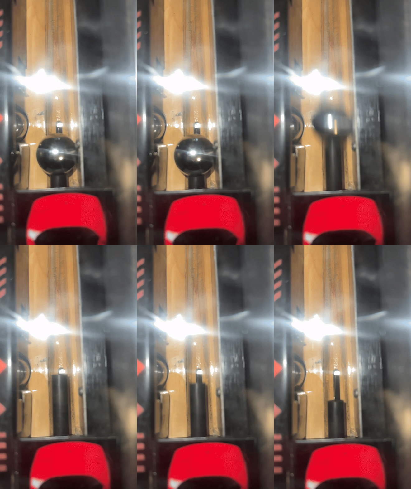
I've been scratch building a Getaway and decided to use a more "modern" police light instead of the spinning MARS lamp. I've got it working and here are the results.

#12675 1 year ago
Quoted from Walamab:

I've been scratch building a Getaway and decided to use a more "modern" police light instead of the spinning MARS lamp. I've got it working and here are the results.

nice result, where did you bought it ?

#12676 1 year ago
#12677 1 year ago
Quoted from Walamab:

It came from amazon.com
amazon.com link »

thx, let's see if I can find it on one of the Amazon EU shops.

#12678 1 year ago
Quoted from frunch:

Def sounds like a broken wire or connector problem at this point.
I would verify continuity from the wiring at J1 of the mini driver board up to the connectors at the main driver board in the backbox.
J1-1 (mini driver board) to J118-3 (main driver board in backbox) (black wire)
J1-4 to J127-5 (brown-yellow)
J1-6 to J107-2 (Violet-orange)

I have continuity on all 3 but it's not on connector J107-2 but on J109-7 in mine.

I suppose I should have 70V on this J109 pin?
To measure, is it just red cable on the power driver 109-7 and ground from the side metal ?

Fuse F101 and F102 are ok

#12679 1 year ago

Yes, red probe on 109-7 and black probe on ground strap or ground test point on driver board.

That is interesting that your wiring goes to a different connector than the schematic says. I'll have to check the wiring on my game and see if it's the same. Could be a mistake in the manual.

#12680 1 year ago
Quoted from frunch:

Yes, red probe on 109-7 and black probe on ground strap or ground test point on driver board.
That is interesting that your wiring goes to a different connector than the schematic says. I'll have to check the wiring on my game and see if it's the same. Could be a mistake in the manual.

Check this ! exactly my issue.
https://pinside.com/pinball/forum/topic/calling-all-getaway-owners-i-need-some-pics#post-1442761

F102 was good but swapped it anyway with a new 3A SB (it was loaded witha 9A one) and.... now it works !!

But now at start of machine the ramp in the back clicks, like it's willing to go up but already is... ???

#12681 1 year ago

Good to know! Glad you found the culprit.

As far as the diverter ramp clicking, I'd verify the switches that detect when it's in the up/down positions are both working properly in switch test.

#12682 1 year ago
Quoted from Walamab:

I've been scratch building a Getaway and decided to use a more "modern" police light instead of the spinning MARS lamp. I've got it working and here are the results.

That looks like a great alternative, especially since the Mars light rotating reflector motor is currently hard to find.

Quoted from Zukram:

Has anyone replaced the motor for the beacon light, and maybe know a source for an original spec'd motor. Mine does not function and looking for a replacement..

Zukram should consider Walamab's alternative to the Mars light.

#12683 1 year ago
Quoted from golfergordy:

That looks like a great alternative

It needs a DC-DC buck converter to drop the +20VDC power to +12VDC at J106-5. But it works quite well. I got my converters here...https://www.amazon.com/gp/product/B07C2QF1T1/ref=ppx_yo_dt_b_search_asin_title

#12684 1 year ago

..

#12685 1 year ago
Quoted from Kerry_Richard:

Matthew2015 where are you located?

I have a Getaway HSII I'll be selling soon. Unfortunately, I'm in Danville, Calif (40 miles East of San Farncisco). I think I'm too far away to make it happen.

#12686 1 year ago

yeah , that's a long ways.

#12687 1 year ago
Quoted from Walamab:

It needs a DC-DC buck converter to drop the +20VDC power to +12VDC at J106-5. But it works quite well. I got my converters here...amazon.com link »

I'm not an electrical guy, so pardon my ignorance (if I'm not making sense here), but doesn't the 12VDC for the mars light come from J-104?, and if so, what's the need to step down 20VDC to 12V at J-106?

edit: I found my record of some actual voltage measurements I made in 2021: 15.9VAC at J-104, and 15.5VAC feeding into the Mars light. The white-red wires from J-104 go to a Triac Driver Board, and then thru another small board and then finally to the Mars light. The voltage on this circuit is AC, not DC like I thought.

#12688 1 year ago
Quoted from Walamab:

I've been scratch building a Getaway and decided to use a more "modern" police light instead of the spinning MARS lamp. I've got it working and here are the results.

This is the same/similar lightbar that I added in addition to the mars lamp (control it through the relay on the PinSound shaker). I actually ended up moving it to the backside of the head because it became a little overwhelming to the senses when playing.

https://pinside.com/pinball/forum/topic/getaway-club-dispatch-run-a-make-on-license-plate-kingpin/page/236#post-6685017

#12689 1 year ago
Quoted from golfergordy:

I'm not an electrical guy, so pardon my ignorance (if I'm not making sense here), but doesn't the 12VDC for the mars light come from J-104?, and if so, what's the need to step down 20VDC to 12V at J-106?

J104-4-5 provides 20VAC which is what the motor for the MARS lamp requires. The LED bar needs 12VDC. I could have tapped the +12VDC at J116-2-3, J117-2-3 J118-2-3 or J114-1-2 but this services the switch matrix, the display the fliptronics board and the playfield and I didn't want to over tax that circuit. J106-5 provides 20VDC for backbox/lamp insert panel flashers. It just made more sense to me to use this as a source.

#12691 1 year ago
Quoted from Walamab:

J104-4-5 provides 20VAC which is what the motor for the MARS lamp requires. The LED bar needs 12VDC. I could have tapped the +12VDC at J116-2-3, J117-2-3 J118-2-3 or J114-1-2 but this services the switch matrix, the display the fliptronics board and the playfield and I didn't want to over tax that circuit. J106-5 provides 20VDC for backbox/lamp insert panel flashers. It just made more sense to me to use this as a source.

My CPU board is out for service, so I can't fire up my game right now to measure the live voltage coming out of J-104 (as well as going to the Mars light), but approx. 1-yr ago I did measure the voltages at both these locations (to solve a problem I was having with the Mars light) and I'm pretty sure they were 12VDC. Also, on p. 2-25 on the operations manual (OM) it shows that the motor is 12V, and I just pulled the motor out of my game and on the motor itself is stamped 12V. Also, the wires coming from J-104-4&5 on my game go up to the Mars light (but 1st go thru 2-small boards in the upper right corner of the back box - #16 & #17 on p. 2-3 of the OM ). Also, the flasher bulbs say 13V on them.

I've only been in this hobby for almost 3-yrs now, but I have found a few errors in the schematics and manuals.

edit: I found my record of actual measured voltages at J104, and at the wires feeding into the Mars light: 15.9VAC (not 12VDC) @ J-104, and 15.5VAC (not 12VDC) feeding into the Mars light.

#12692 1 year ago
Quoted from golfergordy:

My CPU board is out for service, so I can't fire up my game right now to measure the live voltage coming out of J-104 (as well as going to the Mars light), but approx. 1-yr ago I did measure the voltages at both these locations (to solve a problem I was having with the Mars light) and I'm pretty sure they were 12VDC. Also, on p. 2-25 on the operations manual (OM) it shows that the motor is 12V, and I just pulled the motor out of my game and on the motor itself is stamped 12V. Also, the wires coming from J-104-4&5 on my game go up to the Mars light (but 1st go thru 2-small boards in the upper right corner of the back box - #16 & #17 on p. 2-3 of the OM ). Also, the flasher bulbs say 13V on them.
I've only been in this hobby for almost 3-yrs now, but I have found a few errors in the schematics and manuals.

The part description on page 2-25 of the manual is "Motor 12V, 100RPM". It does not specify if the motor is DC or AC.

Here's the wiring diagram and schematic for the triac board. Hint: triac = triode for alternating current.

00_getaway_wiring.jpg00_getaway_wiring.jpg01_getaway_triac.jpg01_getaway_triac.jpg

Note that the triac schematic shows 48VAC but J104-4 and J104-5 are actually the 20VAC transformer secondary. The 48VAC is WHT-BLU. The 20VAC is WHT-RED. Yes, you just discovered another error in the manual.

#12693 1 year ago

I just located my notes from July, '21, when I measured voltages at J-104 and at the Mars Light:
15.9 VAC at J-104, and 15.5VAC @ Mars light (feeding both the motor & bulb).

In my previous posts (from memory) I thought it was 12VDC (sorry). The motor does state 12V on it, which must be 12VAC.

#12694 1 year ago

I own (2)... I got 2nd in a package deal

#12695 1 year ago
Quoted from Kerry_Richard:

I own (2)... I got 2nd in a package deal

I guess I'll allow it then.

#12696 1 year ago

Mr_Tantrum
I need some expert advice .
My pinsound on the HS2 is acting a lil strange and I’m wondering if you can shed some light. Preliminarily , I’m thinking some switch or an EOS is causing this issue.
I took off the glass,
Started a game , music plays, I hit all the bumpers and switches all is good once I hit the right flipper. The music stops and a new sound (I think it’s the turbo sound). So, no music but this aggravating turbo sound I till the ball drains or hits the kick out saucer.
Then music starts again till I hit the flipper.
Any idea?

#12697 1 year ago
Quoted from Hapidance:

Mr_Tantrum
I need some expert advice .
My pinsound on the HS2 is acting a lil strange and I’m wondering if you can shed some light. Preliminarily , I’m thinking some switch or an EOS is causing this issue.
I took off the glass,
Started a game , music plays, I hit all the bumpers and switches all is good once I hit the right flipper. The music stops and a new sound (I think it’s the turbo sound). So, no music but this aggravating turbo sound I till the ball drains or hits the kick out saucer.
Then music starts again till I hit the flipper.
Any idea?

This just started and everything was previously working correctly? Does this occur on multiple orchestrations? Sounds really odd as I don't believe the flippers trigger any sound during game play (they do trigger engine rev sound while ball is waiting to be launched). If you initiate a psrec on the USB, play a game until this issue occurs, and look at the psrec in PinSound Studio, what do you see (i.e. what sound is it that is triggered). As you know sounds are all triggered by some event, so curious what is occuring here.

Another option is to get a new/different USB drive, install an orchestration from scratch on it, then play and see if the issue persists. If not, then some issue with your USB and probably need to reformat and start over. If it does persist then something completely different is occuring.

#12698 1 year ago

Mr_Tantrum
I’m not sure everything was 100% from the start.
I installed the card.
Downloaded various orchistrations onto the usb I purchased with the card and the headset station.
I believe it’s a prolonged engine rev i hear.
It happens on all orchistrations and is quite annoying.

I’m not sure what you mean by “initiating a psrec on the usb” take the usb out ,
Plug it in The computer , open sound studio and see what that sound is for sure?
I haven’t messed around with sound studio yet. Too much good stuff you already made!

I started a game, hit all the switches with a ball, ramps lock and all is well. Hit the right flipper, the music ends and that awfull sound starts playing….
Ugggg
I really think somthing is triggering that sound as opposed to the memory usb

#12699 1 year ago
Quoted from Hapidance:

Mr_Tantrum
I’m not sure everything was 100% from the start.
I installed the card.
Downloaded various orchistrations onto the usb I purchased with the card and the headset station.
I believe it’s a prolonged engine rev i hear.
It happens on all orchistrations and is quite annoying.
I’m not sure what you mean by “initiating a psrec on the usb” take the usb out ,
Plug it in The computer , open sound studio and see what that sound is for sure?
I haven’t messed around with sound studio yet. Too much good stuff you already made!
I started a game, hit all the switches with a ball, ramps lock and all is well. Hit the right flipper, the music ends and that awfull sound starts playing….
Ugggg
I really think somthing is triggering that sound as opposed to the memory usb

In PinSound Studio you can enable recordings. Then, next time you start a game it will record the sound events in a log. You can then open that log in PSS and see exactly when the error occurred and what sound event was called. For some reason the right flipper action is triggering something, so just trying to gain more data on that.

I would also disconnect all cables on the PinSound, closely inspect all pins are alinged properly, then reconnect cables. Probably not an issue, but starting with the basics.

I also assume you have the most recent firmware installed?

#12700 1 year ago
Quoted from frunch:

Good to know! Glad you found the culprit.
As far as the diverter ramp clicking, I'd verify the switches that detect when it's in the up/down positions are both working properly in switch test.

The switch is working fine in switch edge test when i move it by hand.

For some kind of reason the coil is continuing to shoot up at game start. In solenoid test it's going up and down as it should.

Promoted items from Pinside Marketplace and Pinside Shops!
$ 19.00
Electronics
NO GOUGE PINBALL™
 
$ 9.95
Eproms
Pinballrom
 
$ 225.00
Lighting - Interactive
Professor Pinball
 
$ 40.00
5,000
Machine - For Sale
Mesa, AZ
From: $ 209.00
$ 30.00
Playfield - Toys/Add-ons
G-Money Mods
 
From: $ 3.50
Playfield - Other
Rocket City Pinball
 
$ 35.00
Cabinet - Other
Rocket City Pinball
 
5,000
Machine - For Sale
Gilroy, CA
$ 19.00
Boards
Tilted Pinball
 
$ 69.00
Gameroom - Decorations
Pinball Pimp
 
$ 65.00
Playfield - Toys/Add-ons
G-Money Mods
 
$ 10.00
Playfield - Plastics
Pinball Haus
 
$ 9.95
Eproms
Pinballrom
 
$ 329.99
Lighting - Other
Lighted Pinball Mods
 
$ 109.99
Lighting - Led
Lighted Pinball Mods
 
From: $ 100.00
Playfield - Toys/Add-ons
G-Money Mods
 
$ 17.99
Eproms
Matt's Basement Arcade
 
$ 20.00
$ 70.00
Playfield - Toys/Add-ons
RobTune
 
$ 22.50
Playfield - Decals
Pinball Haus
 
Wanted
Machine - Wanted
Fort Lauderdale, FL
$ 20.00
Playfield - Plastics
G-Money Mods
 
$ 85.00
Cabinet - Other
Pinball Haus
 
$ 75.00
Playfield - Toys/Add-ons
G-Money Mods
 
Wanted
Machine - Wanted
Louisville, KY
Great pinball charity
Pinball Edu
There are 13,822 posts in this topic. You are on page 254 of 277.

Reply

Wanna join the discussion? Please sign in to reply to this topic.

Hey there! Welcome to Pinside!

Donate to Pinside

Great to see you're enjoying Pinside! Did you know Pinside is able to run without any 3rd-party banners or ads, thanks to the support from our visitors? Please consider a donation to Pinside and get anext to your username to show for it! Or better yet, subscribe to Pinside+!


This page was printed from https://pinside.com/pinball/forum/topic/getaway-club-dispatch-run-a-make-on-license-plate-kingpin/page/254?hl=number_runner and we tried optimising it for printing. Some page elements may have been deliberately hidden.

Scan the QR code on the left to jump to the URL this document was printed from.