You're currently viewing posts by Pinsider zaza.
Click here to go back to viewing the entire thread.
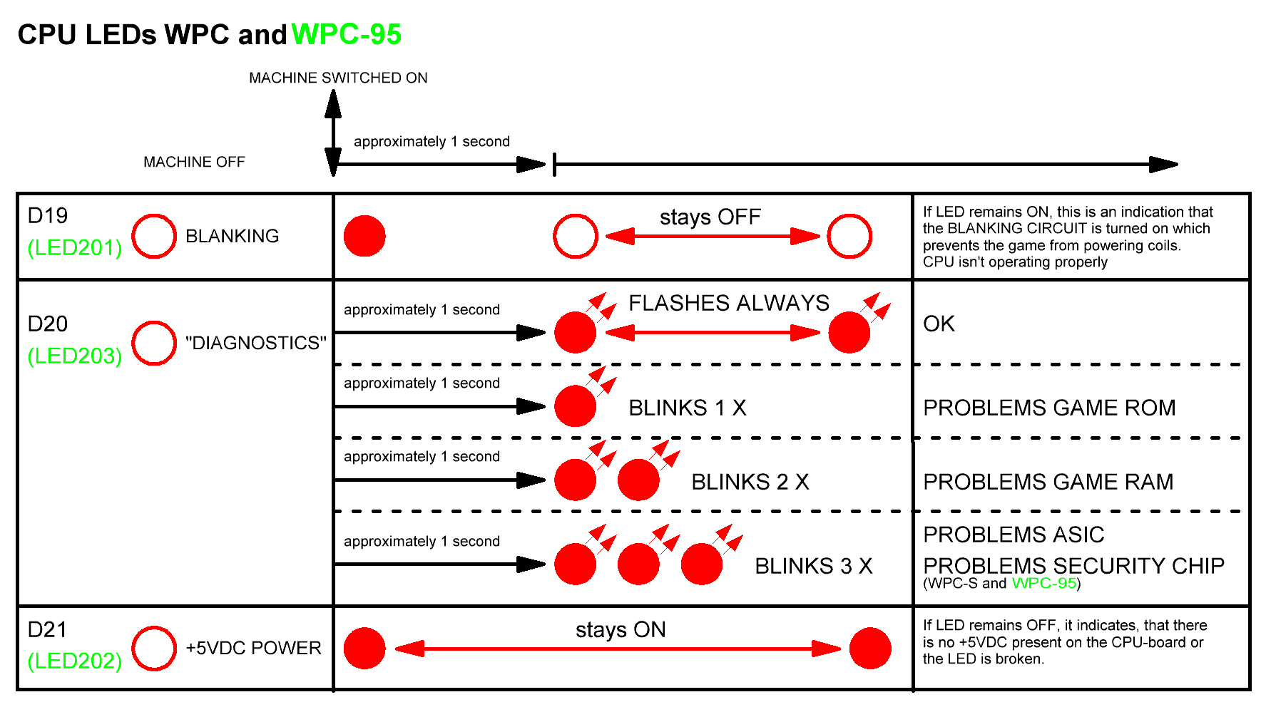
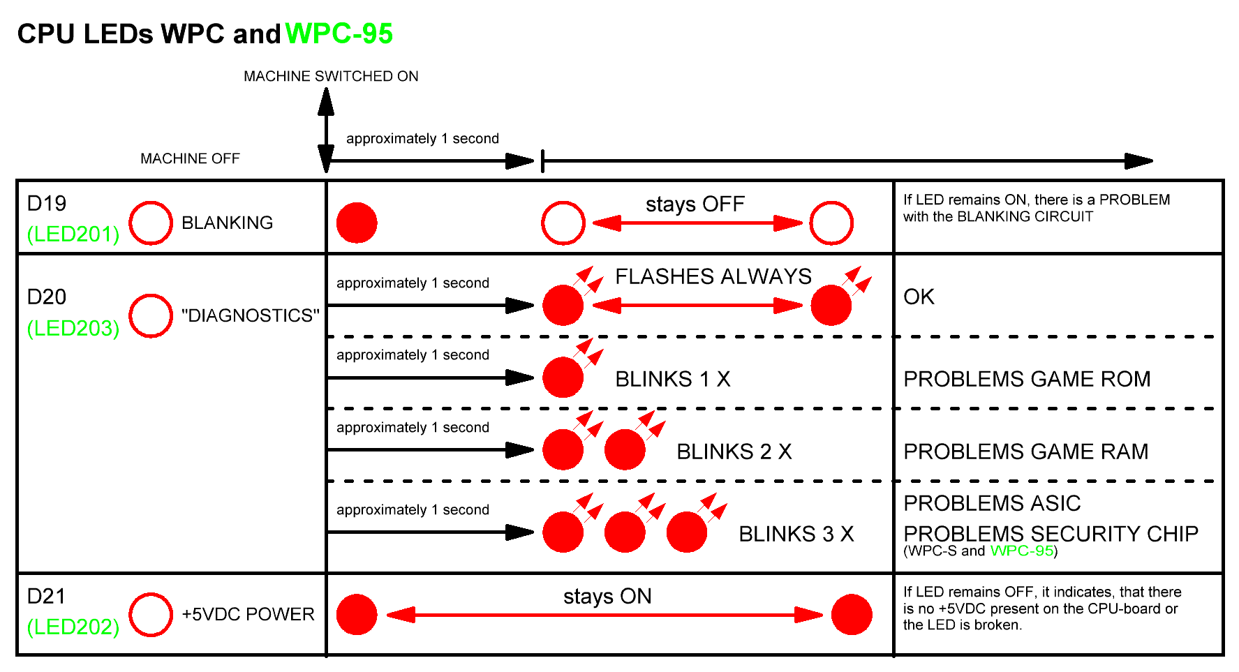
The big picture, I checked it several times for errors but looks OK now.
Quoted from ChrisHibler:something like Zaza is building should help folks that think visually
I think you are right about that, although I can read schematics, these kind of pictures help me as an addition next to the schematics.
Chris H., You are free to publish it on PinWiki.
If someone has suggestions or additions, please tell me.
Thank you .
This picture is automatically compressed with uploading, the original is even better but also 3 times bigger file.
Will have to work on my website and post it there somewhere in the future.
Made some final changes, U14 corrected from LS37 to LS374 and changed text Q1 section into "coin acpt enable".
I will upload it to Chris H. so it can be found on the PinWiki when implemented.
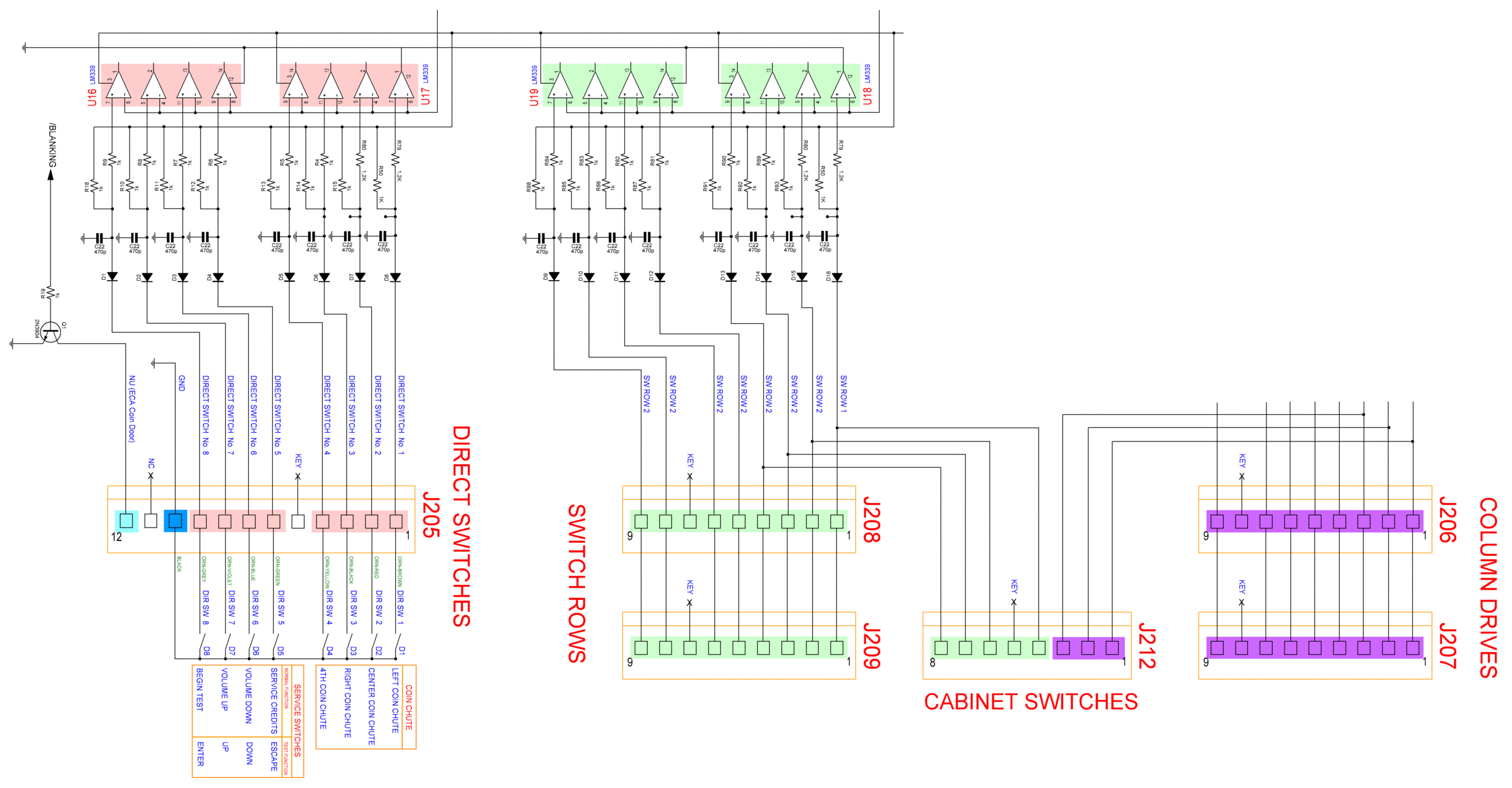
To complete this picture, here is the diagram of the switch inputs with the corresponding colors.
In the pinball-manuals this picture is not entirely error-free, this one is clear and simple redrawn.
enjoy
Thanks Ingo, really appreciate you find this an awsome pic.,
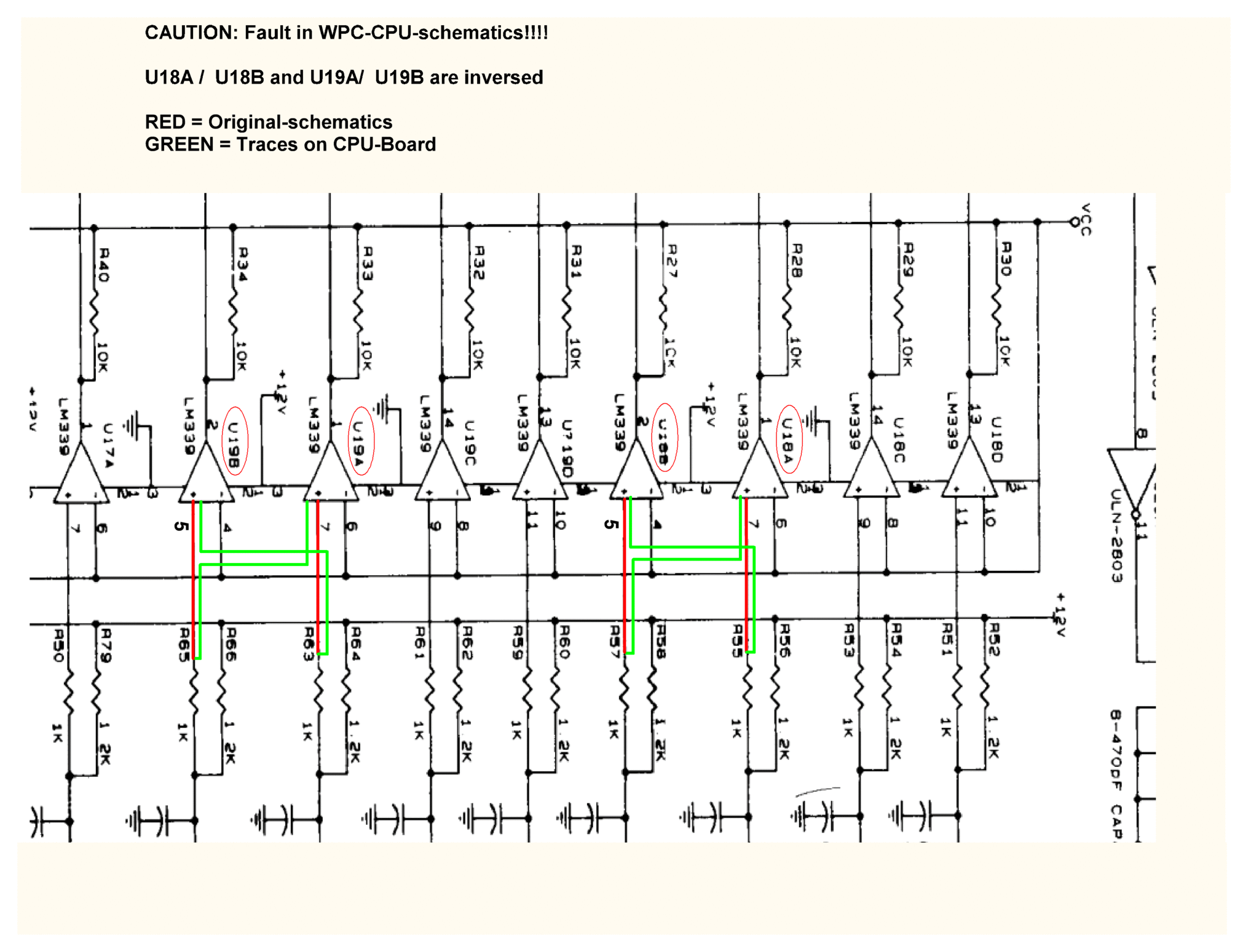
The list with errors goes on and on at this page in the manual.
The individual comparators are so close drawn to each other, that it looks like all pin3 (+12V) and pin12 (GND) are connected to each other.
Also, J205 has only 5 of 12 pins correct in the manual, better skip this page ![]()
Well, as always, don't trust the manual and verify twice.
I'm sure these pictures will help a lot of people. Lot of time has spend in verifying schematics and board, buzzing with meter and scope, but even then a mistake is easy made.
Next picture will be an easy one I think, a balltrough PCB or so, and will get it's own topic instead of hijacking this one ![]() (sorry Demetris)
(sorry Demetris)
Nice work, Ingo but you need a lot of time and patience. ![]()
Quoted from zaza:The individual comparators are so close drawn to each other, that it looks like all pin3 (+12V) and pin12 (GND) are connected to each other.
Quoted from german-pinball:- a few minutes ago, I found a new error, U16 and U17 - GND and V+ are wrong connected -
I think all the pin 3 + 12 of LM339's shouldn't have been drawn in the picture at all, in the schematic-manual the power pin connections of the IC's are already mentioned in the upper right corner.
You're currently viewing posts by Pinsider zaza.
Click here to go back to viewing the entire thread.
Reply
Wanna join the discussion? Please sign in to reply to this topic.

Hey there! Welcome to Pinside!
Donate to PinsideGreat to see you're enjoying Pinside! Did you know Pinside is able to run without any 3rd-party banners or ads, thanks to the support from our visitors? Please consider a donation to Pinside and get anext to your username to show for it! Or better yet, subscribe to Pinside+!


