(Topic ID: 165949)

Working on a Genco Argentine

By Toyguy

7 years ago


Topic Heartbeat

Topic Stats

  • 56 posts
  • 11 Pinsiders participating
  • Latest reply 5 years ago by Toyguy
  • Topic is favorited by 5 Pinsiders

You

Linked Games

No games have been linked to this topic.

    Topic Gallery

    View topic image gallery

    IMG_2241 (resized).JPG
    IMG_2242 (resized).JPG
    IMG_2240 (resized).JPG
    All Set Up (resized).JPG
    PF-Dec2016 (resized).JPG
    First Game (resized).JPG
    PF-Nov2016 (resized).JPG
    Stripped (resized).JPG
    Stripped Overview (resized).JPG
    Steppers1 (resized).JPG
    Gummy (resized).JPG
    Broken Contact (resized).JPG
    diagram for argentine (resized).png
    image-9_(resized).jpg
    IMG_0508_(resized).JPG
    IMG_0509_(resized).JPG

    You're currently viewing posts by Pinsider joenewberry.
    Click here to go back to viewing the entire thread.

    #4 7 years ago
    Quoted from Toyguy:

    I also know they used a rectifier, so if AC looks good I may look at swapping that out.

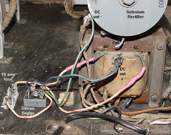
    If it has a disc style rectifier on top of the transformer, you're probably going to want to replace that with a modern silicon variety. Fuse one side of the AC input, too. The original rectifiers look neat, but they usually get worse and worse at their job (more and more AC voltage slips onto the DC line) until they fail catastrophically.

    I wonder if the pop bumper skirts would flatten back out if you sandwich them between a couple pieces of glass and stick them in the sun.

    1 week later
    #12 7 years ago

    The rectifier wiring should be pretty simple. Here is Clay's picture of it:

    http://www.pinrepair.com/em/genco1.jpg

    It's not identical to yours, but the same strategy should apply. The two outer wires from the transformer to your old rectifier are the AC lines, the middle line should be positive DC and the lug on the side of the rectifier should be negative DC. The new rectifier should have two corners labeled ~ that get the AC wires hooked to them (makes no difference which goes where), and one corner a piece labeled + and -. They get the + DC and - DC wires attached to them, respectively. You want to disconnect the AC and positive DC lines from the old rectifier altogether.

    This thread ( http://www.pinballcontrollers.com/forum/index.php?topic=1304.0 ) suggests the "Start" lug is the common, so it would get the neutral wire and the hot wire would go to one of the voltage inputs. I'd say high tapping it at 125 isn't really necessary since it's going to be DC rectified. I'd probably put it at 115 or 105.

    #14 7 years ago

    Hmm. It would seem to make sense to put it on terminal 4. If the timer switch is closed, then it keeps neutral connected to Start. When the timer drops out, that connection drops out too. Do the wires to the coin door go to a start button/coin mech switch?

    Just taking a guess, I'd say it goes on 4. The game is totally dead until you close whatever switch on the coin door wakes it up. It comes to life momentarily, long enough to engage the timer, which holds on the game through 4 and 6 on the terminal. When the timer runs out, the switch opens, neutral is disconnected, and the whole game would go dead.

    Do you happen to know if the timer is for sure original? Clay always seems to be removing timers from games in this era, where they were added by operators to keep people moving along.

    Oh, also, in case my description of hooking up the rectifier wasn't good enough, here is a Microsoft Paint illustration.

    Genco to Modern Rectifier ModificationGenco to Modern Rectifier Modification

    Obviously, you don't have to cut the wires where I put "Cut" just desoldering them will suffice.

    #22 7 years ago

    If you put a meter lead on the one lug by itself and touch the other lead to each of the other three lugs and negative DC lead on the chassis, one at a time, one pair should give you 6VAC.

    #24 7 years ago

    On further reflection, it should be one of the AC lines. Here is another MS Paint special illustrating it. Two AC wires go together to give the AC voltage that the rectifier turns into DC to drive the solenoids. The one AC wire by itself and one of the other two AC lines gives you your six volts AC for the lights.

    diagram for argentine (resized).pngdiagram for argentine (resized).png

    #26 7 years ago

    Gah, you're right. You are short a wire for that. Hmm. Well, I guess it's back to testing the wires with your meter.

    You could also check for continuity between the wires going to one of the lightbulbs. I see one side of the light socket going to that lone lug on the transformer. Where does the other side go? Find that out and you know what to hook back up to get back the lights.

    #28 7 years ago

    If you check for continuity between the other side of the lightbulb and the four wires on the new rectifier, are any of them connected?

    #31 7 years ago

    Just bad bulbs. Hilarious. Well, at least it's working now. Keep us updated on your progress.

    #33 7 years ago

    I would think that it's a match unit. Since it's on a continuous stepper, just like later match units, and the numbers correspond to the first four digits of the lowest to the highest possible scores. Are the hidden numbers lit up all the time, though, rather than just in Game Over?

    #40 7 years ago

    If it has no regular credit unit, I imagine it would make no sense to have a match feature, since it can't award free games to anything. If it has a knockoff button, then you are probably on to the solution.

    You're currently viewing posts by Pinsider joenewberry.
    Click here to go back to viewing the entire thread.

    Reply

    Wanna join the discussion? Please sign in to reply to this topic.

    Hey there! Welcome to Pinside!

    Donate to Pinside

    Great to see you're enjoying Pinside! Did you know Pinside is able to run without any 3rd-party banners or ads, thanks to the support from our visitors? Please consider a donation to Pinside and get anext to your username to show for it! Or better yet, subscribe to Pinside+!


    This page was printed from https://pinside.com/pinball/forum/topic/working-on-a-genco-argentine?tu=joenewberry and we tried optimising it for printing. Some page elements may have been deliberately hidden.

    Scan the QR code on the left to jump to the URL this document was printed from.