(Topic ID: 336664)

White Water / WH2O - Scratch Build

By MiniPinHead

11 months ago


Topic Heartbeat

Topic Stats

  • 447 posts
  • 52 Pinsiders participating
  • Latest reply 7 hours ago by Langless28
  • Topic is favorited by 62 Pinsiders

You

Linked Games

Topic Gallery

View topic image gallery

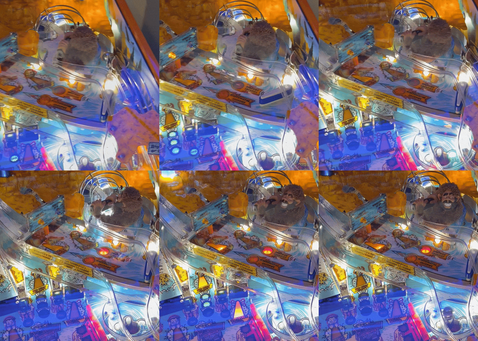
IMG_7232 (resized).jpeg
IMG_7228 (resized).jpeg
IMG_7224 (resized).jpeg
IMG_7220 (resized).jpeg
IMG_7222 (resized).jpeg
White Water 12-7043 Wire.pdf (PDF preview)
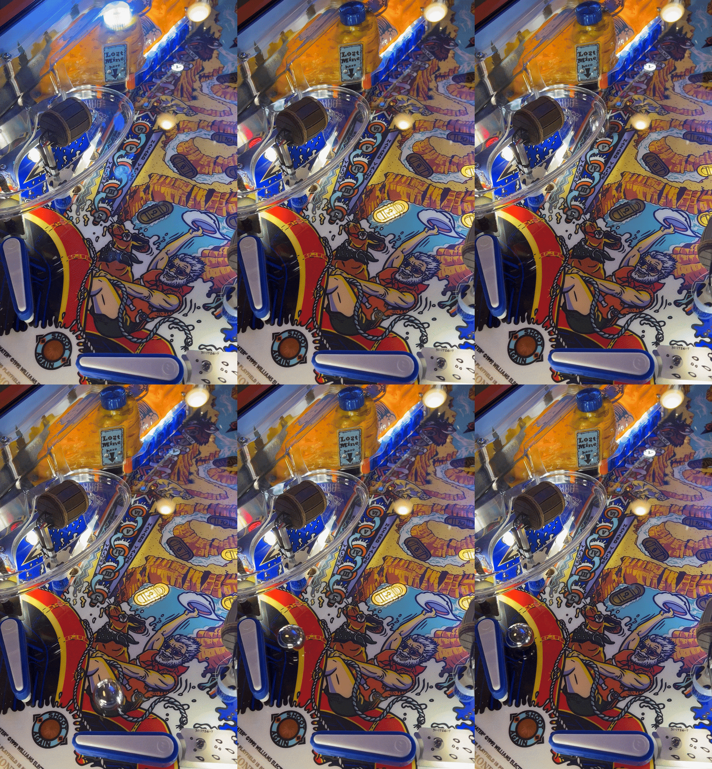
IMG_6682-ezgif.com-optimize.gif
IMG_6681 (resized).jpeg
IMG_6458 (resized).jpeg
IMG_6456 (resized).jpeg
IMG_6453 (resized).jpeg
IMG_6443-ezgif.com-optimize.gif
IMG_6437 (resized).jpeg
IMG_6436 (resized).jpeg
IMG_6438 (resized).jpeg
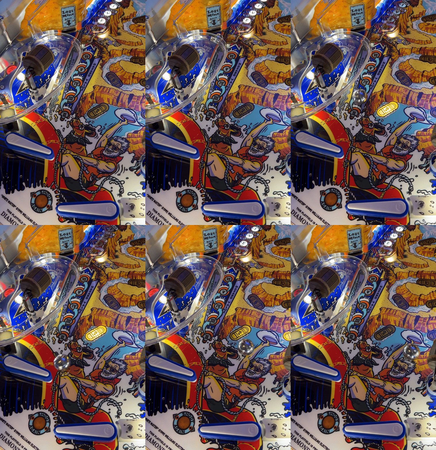
IMG_6376-ezgif.com-video-to-gif-converter.gif
There are 447 posts in this topic. You are on page 1 of 9.
18
#1 11 months ago

Brand new to pinball as of 2023 (Thank You Pinside, Thank You @nonsense). Cut my teeth on a Motordome revitalization (Thank You @vid1900, Thank You @bigal56). Eventually, got familiar with the pins out there, and reviewed the most family-friendly options and which ones could be built from scratch. The rationale for the scratch build was to make things more affordable by utilizing funds over time and to avoid buying replacement parts to revitalize an existing table (and to have fun and learn). Identified White Water (WH2O) as the best option and decided that an quality, scratch build was in order!

Will be updating this first post with many Thank You notes over time for those of you who have made this goal of making an affordable, quality WH2O from scratch possible. Some of you kind, helpful Pinsiders have already given advice, some have provided information and knowledge, some sweet deals on parts, and some extremely kind gifts on parts (looking at you @pinkitten). An updated list of parts and information that is still needed is also below. Lastly, will try to consolidate a list of resources that have been helpful in this project. All of these lists can be found below.

For this thread, please feel free to post any advice, answers (I'll need them!), experiences, ideas, information, links, photos, questions, etc. All is welcome!

This project has already started, but the break down for this thread will be in ~5 parts:
1. Parts identification, accumulation, and documentation (some minor assembly for ease of tracking parts will occur)
2. Parts assembly and documentation (some minor installation)
3. Cabinet and playfield assembly
4. Wiring and PCBs
5. Testing and troubleshooting

Now for the fun part:

Thank You:
-Action Pinball for the great prices on hard-to-obtain parts
Aflacjack for producing the Yeti mod and reproduction topper information
Bryan_Kelly for the amazing, robust set of WH2O restoration / tear-down photos... in high definition Thank you!
Cliffy for the high-quality Cliffy’s Protectors. Wouldn’t put a pinball on a playfield without them Thank you so much for making these
-Custom Playfield Reproductions (CPR) for the sweet deal on the backglass and plastics (#Motordome has its uses )
Damonator for the advice, knowledge, information, support, wire form measurements, and photos AND providing Mantis will all the metal components for production (thank you!)
DanQverymuch for the nice deal on the 6/7 Starship Fantasy reproduction ramps. A great lrosent345 product!
Davi for making the wire form ramps AND lamp PCBs AND for all the advice and knowledge shared (thank you!)
Dinger for the mylar guidance, encouragement, and boulder
Drano for the WH2O specialized guide lane plastic
DumbAss for making the COMPLETE set of WPC PCBs AND for all the thoughtful knowledge and advice shared, as well as the amazing ongoing support! Couldn't do this without you (thank you so very much!)
flashinstinct for the very useful decal set and sweet deal (thank you!)
Hammerhead for the nice playfield, apron, and gifted shooter gauge (thank you!)
herbertbsharp for the access to an in-person White Water to take measurements and photos (thank you!)
High_End_Pins for leading by example and sharing so many pro tips and high-quality photos. Your advice has saved me multiple times Thank you!
Highclasspinball for the great customer service and awesome deal on the replacement Rad Cals and playfield set
ibis for making the best looking backboard and rails out there. Can't build a playfield without them (thank you!)
joeraptor2003 / PinGraffix for the great quality PinBlades (and the heads up for the sale!)
kruzman for the playfield advice and guidance
kstairmantis / Mantis for the making all the metal components not previous available so that this scratch build and many other projects may benefit. A proper scratch build wouldn't be possible without Mantis! (thank you!)
-Lance from the UK for the great deal on various printed circuit boards!
Leechman for the amazing deal on the Rad Cals, white boulders, and white skull mod (thank you!)
lrosent345 for the high quality Starship Fantasy WH2O reproduction boulders and ramps, which feel super sturdy and look flawless. Thank you for all your effort!
marcopinball / Marco for the VAST array of needed parts and amazing customer service. Scratch builds wouldn't be possible without Marco
Pbpins for the nice deal on the display/speaker plastic
Pinball Spare Parts Australia (PSPA) for the great prices on hard-to-obtain parts
pinballlife and for the BEST prices and making pinball restorations and scratch builds affordable...AND for taking the plunge and offering the HomePin WPC reproduction transformer (thank you!)
PinballPimp for the nice decal mods
-The Pinball Resource and Steve (and Lou & team) for the quality parts made to original specifications and design (thank you!)
pinballshark for the epic shooter rod and powder coat information
pinballtommy for the great deal on the WH2O back box with hardware and other valuable WH2O odds and ends
Pinkitten for the above and beyond generosity AND awesome gift of a complete coin door (thank you!)
pintoys for the nice deal on the WPC The Addams Family cabinet
PinWoofer for the awesome sound system, the GT 8in 5.25in WPC Super Kit
radium for the ongoing, amazing, selfless support. Couldn't do this project without the shared connection, shared knowledge, and very impressive 3D printing AND metal fabrication skills (thank you!)
ralphwiggum for the very appealing 3D apron cards
RobF for the 3D printed Big Foot mold
robin for approving this thread, haha
rockwell (Wire-Bot) for the most amazing cable and wiring support this hobby could ask for This undertaking is so much less intimidating with Wire-Bot in your corner (thank you!)
ryanwanger / Comet for the amazing LED WH2O kit... and candy, haha
Sonic & blubboman for the Magnetic Reed Switches (MRSs) - "If you love your pin, why don't you MRS it"
Soulrider911 for the "treasure trove" of WH2O pics and the extremely useful WH2O restore thread (thank you!)
-ThePinballWizard for the great prices on quality parts
Titan_Pinball for the great rubbers and quality products
Tophervette for the scratch build support
truemagoo102 for the ongoing support AND encouraging me to make this thread (thank you!)
vid1900 for the encouragement, guidance, and all of the useful guides posted on Pinside
wallybgood for the huge saves and guidance on corrections that has (and will) be needed (thank you!)
wrd1972_PinDoc for the strong and sturdy playfield rotisserie set
zene10 for the very cool Big Foot mod (if you have to ask, you need to buy it )

Parts Needed:
None

Resources:
-WH2O Manual: https://www.ipdb.org/files/2768/Williams_1993_White_Water_English_Manual.pdf
-WPC Schematic Manual (Revised May 17, 1993)
https://www.ipdb.org/files/2768/Williams_WPC_Schematics_Revised_May_17_1993_.pdf

-WH2O Parts Index: https://www.ipdb.org/files/2768/Williams_1993_White_Water_Parts_List.txt
-Parts Index Search: https://moll.no/pinball/parts/
-Williams "Red Book": https://www.planetarypinball.com/williamsbally-parts-manuals

-WH2O Club Thread: https://pinside.com/pinball/forum/topic/whitewater-club-lifejackets-not-required
-WH2O Topper Thread: https://pinside.com/pinball/forum/topic/white-water-topper-poor-mans-version

-BR80 restoration thread: https://pinside.com/pinball/forum/topic/whitewater-restoration
-dmacy restoration thread: https://pinside.com/pinball/forum/topic/whitewater-deep-shop-and-light-project-refresh
-Drano missing plastic thread: https://pinside.com/pinball/forum/topic/white-water-missing-plastic-coming-soon
-DumbAss PCBs thread: https://pinside.com/pinball/forum/topic/dumbass-test-and-reproduction-pcbs
-High_End_Pins restoration threads: https://pinside.com/pinball/forum/topic/hep-this-week-9-17-18/page/228 and https://pinside.com/pinball/forum/topic/hep-this-week-9-17-18/page/252#post-7649365
-pinballinreno CPR backglass trim thread: https://pinside.com/pinball/forum/topic/cpr-backglass-trim
-Soulrider911 restoration thread: https://pinside.com/pinball/forum/topic/restoration-rough-water-to-white-water-
vid1900 line filter / power junction box thread: https://pinside.com/pinball/forum/topic/replacing-line-cords-plugs-wall-sockets-vids-guide
-Pinscape build guide: http://mjrnet.org/pinscape/BuildGuideV2/BuildGuide.php

Example of Progress on Parts Index

Example of Progress on Parts IndexExample of Progress on Parts Index

Now done via Google spreadsheet thanks to radium

Online Spreadsheet for Ease of UseOnline Spreadsheet for Ease of Use

#2 11 months ago

Big undertaking...
Best of luck .....

#3 11 months ago

The nice thing with obtaining complete assemblies or mechanisms (mechs) is it can knock out 40+ part numbers from the Parts Index
Flippers: https://www.pinballlife.com/full-flipper-assembly-for-williamsbally-machines-from-021992-to-101998.html (2 needed (Upper Playfield is electronic))
Pop Bumpers: https://www.pinballlife.com/williamsbally-pop-bumper-assembly.html (3 needed)
Pop Bumper Assembly and Full Flipper AssemblyPop Bumper Assembly and Full Flipper Assembly

Also, having a nice Pinsider reach out with a partially populated back box knocks a few more parts off the list and provides a nice start to building the completed back box. If anyone needs a 1927.# A-14092-3 WPC Mounting Plate Assembly (good for BR, BSD, CftBL, DW, FT, HS2, WH2O), or wants one in stainless steel, try and reach out to Mantis and express your need
WH2O Back BoxWH2O Back Box

#4 11 months ago

Starting off easy with the B-11873-2 Bottom Arch Kicker Assembly.

Assembled it using the kit from Marco. Noticed 5/16” screws are long enough where the plunger could scrape up against these, depending on how far the plunger goes against the pressure of the spring. Does anyone know if the plunger goes in that far (i.e., the kicker sticks out that far)? Or should I just get 1/4” screws (it is that close to clearing)?

Thank you

IMG_8737 (resized).jpegIMG_8737 (resized).jpegIMG_8738 (resized).jpegIMG_8738 (resized).jpegIMG_8739 (resized).jpegIMG_8739 (resized).jpeg

Edit:

Had the 8-32 1/4” screws w/ lock and just swapped them so I never have to worry about it. Clearance is perfect. Bracket still is completely stable. Added the Blue Loctite because why not Updated my manual and parts tracker. IMPORTANT: the index shows this part needs a 1/4” screw, but the manual shows 5/16”. Index is how you want to go on this. I’ll send Marco a note just to help anyone out that gets this assembly kit.

Make sure your’s doesn’t have wear that you’d like to replace.

IMG_8740 (resized).jpegIMG_8740 (resized).jpeg

#5 11 months ago

With the B-10686-1 Knocker Assembly, definitely prefer the lugs oriented as the manual described, so they aren’t right up against the metal venting screen in the back box. I also don’t want the bottom plastic of the coil to get pressure from the back box or put a dent in the wood or paint if possible. Adding washers to raise it off the back box doesn’t seem like a good idea, as support for the bracket would lessen and you might end up sending the washer into the wood of the backbox.

This came assembled, but disassembled it so could square away the brackets and coil on a hard surface. Something to grip both nuts and keep them straight is useful if you’re working with a newer style replacement assembly.

IMG_8742 (resized).jpegIMG_8742 (resized).jpeg
#6 11 months ago

I would advise not to you thread lock it’s not necessary and will give you or someone down the road headaches.

#7 11 months ago

Well written post and an impressive undertaking for being so new to the hobby.

Regrettably, I having nothing to offer in the form of advice (having no expertise, myself); however, I wanted to wish you the best of luck with this big adventure and will look forward to following your progress as you add updates!

#8 11 months ago

I've got tons of tear down pics.

If you need anything, just let me know.

#9 11 months ago
Quoted from Pintopia:

I would advise not to you thread lock it’s not necessary and will give you or someone down the road headaches.

Maybe just stick to doing the stops? I appreciate the words of caution before I get carried away

Quoted from Master_of_Trolls:

Well written post and an impressive undertaking for being so new to the hobby.
Regrettably, I having nothing to offer in the form of advice (having no expertise, myself); however, I wanted to wish you the best of luck with this big adventure and will look forward to following your progress as you add updates!

Thank you so much! It wouldn’t be possible for me without Pinside and all of you helpful and encouraging Pinsiders

Quoted from Bryan_Kelly:

I've got tons of tear down pics.
If you need anything, just let me know.

I’m always referencing photos to double check on parts for ordering and organizing. It’s tough to pick out stock sizes, etc. without Manual references or clear Parts Index sections. Having even more high definition photos would be helpful. I’ll reach out! Thank you so much

#10 11 months ago

I wonder which is crazier.... your printed BOM or my Excel version?

Screenshot_448.pngScreenshot_448.png

#11 11 months ago
Quoted from radium:

I wonder which is crazier.... your printed BOM or my Excel version?
[quoted image]

I’m also using a Google “Sheet” and an Apple “Note” haha. Being inspired by you, I’ll get that paper list completely converted to digital

Had to order some hardware to get a few assemblies built. So did a simple cleaning (soap and water) of the oil off the # 23-6686 Blue, Round Bumper Pad and combined with the # 01-10673-1 Ball Deflector Bracket to make the # A-15813 Deflector Assembly (goes by the multi ball popper). Pad has some indents, so eventually will get a replacement from Marco and keep this pad as a backup (didn’t get from Marco).

IMG_8846 (resized).jpegIMG_8846 (resized).jpegIMG_8847 (resized).jpegIMG_8847 (resized).jpegIMG_8848 (resized).jpegIMG_8848 (resized).jpeg

Another update, one of the talented 3D Printing Threaders, @RobF, has been making amazing progress on reproducing the # A-16047 Big Foot Assembly body mold. Very useful if you want to replace, revitalize, or update your Big Foot fur.

pinside.94318dd818ee6d4e3a858bba92bad160c811b4b3 (resized).jpegpinside.94318dd818ee6d4e3a858bba92bad160c811b4b3 (resized).jpegIMG_8604 (resized).jpegIMG_8604 (resized).jpegIMG_8613 (resized).jpegIMG_8613 (resized).jpeg

#12 11 months ago

Is anyone willing to get these measurements of the WH2O wireform guides # 12-7051 Wire - Boulder Garden and # 12-7052 Wire - Boomerang?

Thank you

Wireform Guides (resized).jpgWireform Guides (resized).jpg

And also curious if anyone knows the tool needed to make the barbs or flanges on the ends of the wireform guides? It'd be for a 3/32" stainless steel rod.

Wireform Barb Flange (resized).jpgWireform Barb Flange (resized).jpg

Added 40 days ago:

Measurements and print out for bending are here: https://pinside.com/pinball/forum/topic/white-water-wh2o-scratch-build/page/5#post-7887416

#13 11 months ago

Looking at ordering the spacers / standoffs. Unfortunately, most aren't made like stock, so stock sizes need to be pieced together in most cases. Unless otherwise specified, looking at all 1/4" Hex Size, Zinc-Coated Brass:

488 ...4 02-4564 standoff m-f 10-32 x 7/8" 3/8hex (3) (Big Foot Mechanism Assembly)
https://www.mcmaster.com/92700A022/ (m-f 7/8")

665 ..3 02-4252-20 spacer f-f 6-32 x 1-1/4" (1) (Upper Playfield - needs threaded rod to pair with 02-4434 post spacer (1" tall) and tee nut (1/4" tall"))
https://www.mcmaster.com/90308A335/ (f-f 1-1/4")
https://www.mcmaster.com/95412A420/ (SS) (6-32 rod 3")

1508 .2 02-4796-12 spacer m-f 8-32 x 3/4" close thd (1) (Insanity Falls (back end) - goes on 8-32 standoff bracket)
https://www.mcmaster.com/90308A197/ (f-f 3/4")

1509 .2 02-4796-34 spacer m-f 8-32 x 2-1/8" close thd (1) (Insanity Falls (middle) - goes on 8-32 standoff bracket)
1-1/4" (1.25) + 7/8" (0.875) = 2-1/8" (2.125)
https://www.mcmaster.com/92700A455/ (m-f 7/8")
https://www.mcmaster.com/90308A201/ (f-f 1-1/4")

1510 .2 02-4796-38 spacer m-f 8-32 x 2-3/8" close thd (1) (Insanity Falls (front end) - goes on 8-32 standoff bracket)
1-1/2" (1.5) + 7/8" (0.875) = 2-3/8" (2.375)
https://www.mcmaster.com/92700A455/ (m-f 7/8")
https://www.mcmaster.com/90308A202/ (f-f 1-1/2")

1511 .2 02-4250-21 spacer m-f 6-32 x 1-5/16" (1) (Upper to Lower Ramp (front end) - Main Playfield, Front Right - goes on bumper post)
7/16" (0.4375) + 7/8" (0.875) = 1.3077 (closest to 1.3125)
https://www.mcmaster.com/92700A489/ (m-f 7/16")
https://www.mcmaster.com/92700A445/ (m-f 7/8")

1512 .2 02-4252-18 spacer f-f 6-32 x 1-1/8" (1) (Suicide Canyon Ramp - needs threaded rod to pair with 02-4434 post spacer (1" tall) and tee nut (1/4" tall"))
https://www.mcmaster.com/91115A529/ (SS)
https://www.mcmaster.com/95412A420/ (SS) (6-32 rod 3")

1518 .2 02-4629-1 post m-m 10-32 x 2-3/8" 3/8rnd (4) (Main Playfield, Back Right - Upper Playfield Support (underneath) - needs threaded rod on both ends)
1-1/2" (1.5) + 7/8" (0.875) = 2-3/8" (2.375)
https://www.mcmaster.com/90308a308/ (m-f 1-1/2")
https://www.mcmaster.com/92700A022/ (f-f 7/8")
https://www.mcmaster.com/93025A863/ (10-32 rod 1.5")

For the four posts that support the Upper Playfield, one side of the post is fully threaded (guessing 1" length) and then the other side is partially threaded (guessing 1/2" threaded and 1/2" unthreaded). Looking at going fully threaded on both sides.

Going to order for a second Pinsider also doing a scratch build, so the threaded rod quantity might be more than needed for one build.

Anyone see any issues?

Spacers 1 (resized).jpgSpacers 1 (resized).jpgSpacers 2 (resized).jpgSpacers 2 (resized).jpgSpacers 3 (resized).jpgSpacers 3 (resized).jpgSpacers 4 (resized).jpgSpacers 4 (resized).jpg Added 40 days ago:

Note: 6-32 rods are not needed (do not purchase), as the standoffs are mounted onto post heads, sometimes on top of bumper posts

#14 11 months ago

Updated the spacers / standoffs from the previous post to all be Stainless Steel (links updated below). Added some additional notes. Lastly, updated the 6-32 rods to be 2" to avoid needing to cut them:

488. ...4 02-4564 standoff m-f 10-32 x 7/8" 3/8 hex (3) (Big Foot Mechanism Assembly)
https://www.mcmaster.com/91075A022/ (m-f 7/8")

665. ..3 02-4252-20 spacer f-f 6-32 x 1-1/4" 1/4 hex (1) (Upper Playfield - needs threaded rod to pair with 02-4434 post spacer (1" tall) and tee nut (1/4" tall"))
https://www.mcmaster.com/91115A134/ (f-f 1-1/4")
https://www.mcmaster.com/95412A875/ (6-32 rod 2")

1508. .2 02-4796-12 spacer m-f 8-32 x 3/4" close thd 1/4 hex (1) (Insanity Falls (back end) - goes on 8-32 standoff bracket)
https://www.mcmaster.com/91115A197/ (f-f 3/4")

1509. .2 02-4796-34 spacer m-f 8-32 x 2-1/8" close thd 1/4 hex (1) (Insanity Falls (middle) - goes on 8-32 standoff bracket)
1-1/4" (1.25) + 7/8" (0.875) = 2-1/8" (2.125)
https://www.mcmaster.com/91075A455/ (m-f 7/8")
https://www.mcmaster.com/91115A202/ (f-f 1-1/4")

1510. .2 02-4796-38 spacer m-f 8-32 x 2-3/8" close thd 1/4 hex (1) (Insanity Falls (front end) - goes on 8-32 standoff bracket)
1-1/2" (1.5) + 7/8" (0.875) = 2-3/8" (2.375)
https://www.mcmaster.com/91075A455/ (m-f 7/8")
https://www.mcmaster.com/91115A203/ (f-f 1-1/2")

1511. .2 02-4250-21 spacer m-f 6-32 x 1-5/16" 1/4 hex (1) (Upper to Lower Ramp (front end) - Main Playfield, Front Right - goes on bumper post)
7/16" (0.4375) + 7/8" (0.875) = 1.3077 (closest to 1.3125)
https://www.mcmaster.com/91075A489/ (m-f 7/16")
https://www.mcmaster.com/91075A445/ (m-f 7/8")

1512. .2 02-4252-18 spacer f-f 6-32 x 1-1/8" 1/4 hex (1) (Suicide Canyon Ramp - needs threaded rod to pair with 02-4434 post spacer (1" tall) and tee nut (1/4" tall"))
https://www.mcmaster.com/91115A529/ (f-f 1-1/8")
https://www.mcmaster.com/95412A875/ (6-32 rod 2")

1518. .2 02-4629-1 post m-m 10-32 x 2-3/8" 3/8 hex (instead of 3/8 rnd) (4) (Main Playfield, Back Right - Upper Playfield Support (underneath) - needs 1" threaded rod on both ends)
1-1/2" (1.5) + 7/8" (0.875) = 2-3/8" (2.375)
https://www.mcmaster.com/91075A178/ (m-f 1-1/2")
https://www.mcmaster.com/91115A798/ (f-f 7/8")
https://www.mcmaster.com/95412A895/ (rod 1.5")

Encouraging notes on the 665. # 02-4252-20 & 1512. # 02-4252-18 6-32 rods, and the 1518. # 02-4629-1 10-32 rod:

For 665. # 02-4252-20 & 1512. # 02-4252-18 6-32, the f-f 1"+ standoffs in this replacement build are partially threaded 0.375". Combined with the fully threaded 1" bumper spacer and 0.25" tee nut (1.625" total), only 0.375" is left as a remainder. Worst case this excess 0.375" rod has to get cut, but realistically, it'll just be exposed past the base of the tee nut on the underside of the playfield and left.

For 1518. # 02-4629-1, the f-f 7/8" standoff in this replacement build is fully threaded and the m-f 1-1/2" standoff exposed male thread is 0.375" long. Combined, these standoffs leave 0.5" female threaded space, so the 1.5" threaded rod in the combined standoff leave the desired 1" threaded rod exposed, without needing to cut any rod down.

Added 90 days ago: Note: 6-32 rods are not needed (do not purchase), as the standoffs are mounted onto post heads, sometimes on top of bumper posts.

#15 11 months ago

Posting this here so I don't lose it. Some hard to find part numbers and where they go:

761. .2 A-15833 back panel assy 1
762. ..3 11-831-50018 back panel-50018 1
763. ..3 01-11040 brkt ramp support 1
764. ..3 01-9170 brkt gusset 2
765. ..3 4506-01106-16B sss 6-32x1 4 (goes into the rails through the bottom of the gusset (2 per gusset))
766. ..3 4106-01033-08B sms #6X 1/2 p-tr-hd-a 10 (goes into the back board / panel)
767. ..3 01-11154 brkt right mountain 2

Back Board PanelBack Board Panel

#16 11 months ago

Great job. This is gonna turn out nice!!

#17 11 months ago
Quoted from jazc4:

Great job. This is gonna turn out nice!!

Thank you so much! There are a lot of details and subtleties in the Manual and Parts Index to go over, in order to make sure you understand what parts are needed and to get the correct ones. Anxious to get more assemblies put together, so found some time to do a quick 561. # A-15843 Upper Right Electronic Flipper Assembly build this morning.

Utilized Action Pinball’s (AP's) guide on how to make a suitable replacement: https://www.actionpinball.com/parts.php?item=A-15843

Utilized the build list from AP’s right flipper assembly build: https://www.actionpinball.com/parts.php?item=FLASSY2_R

Utilized a 583. # FL-11630 red coil and 586. # 10-376 coil spring.

PartsPartsTopTopBottomBottom

What was most time consuming about this build was being a penny pincher and sourcing the parts in the least expensive way possible. AP did get their cut, though

#18 11 months ago
Quoted from MiniPinHead:

Thank you so much! There are a lot of details and subtleties in the Manual and Parts Index to go over, in order to make sure you understand what parts are needed and to get the correct ones. Anxious to get more assemblies put together, so found some time to do a quick 561. # A-15843 Upper Right Electronic Flipper Assembly build this morning.
Utilized Action Pinball’s (AP's) guide on how to make a suitable replacement: https://www.actionpinball.com/parts.php?item=A-15843
Utilized the build list from AP’s right flipper assembly build: https://www.actionpinball.com/parts.php?item=FLASSY2_R
Utilized a 583. # FL-11630 red coil and 586. # 10-376 coil spring.
[quoted image][quoted image][quoted image]
What was most time consuming about this build was being a penny pincher and sourcing the parts in the least expensive way possible. AP did get their cut, though

If I'm not mistaken, you want the older style conical spring on the upper flipper instead of the one you have. I don't believe you have room for the one you nave.

#19 11 months ago

Doing an addams scratch build currently but really would love to do this game next. Rooting for you!

#20 11 months ago
Quoted from Bryan_Kelly:

If I'm not mistaken, you want the older style conical spring on the upper flipper instead of the one you have. I don't believe you have room for the one you nave.

Thank you very much for kindly catching that and providing the correction Bryan! You can even see my incorrect part number on the floor and I even stated the correct one in my post, haha. Thank you again

I'll make the fix and post an update.
Correction for A-15843Correction for A-15843

Quoted from orangegsx:

Doing an addams scratch build currently but really would love to do this game next. Rooting for you!

TAF looked very intimidating! I got the early impression that a lot of parts were very hard to find. I hope you finish soon, so that you can pass me!

Edit:

Made the required changes. Thank you again Bryan!

IMG_8943 (resized).jpegIMG_8943 (resized).jpeg

#21 11 months ago

Scratch builds are pretty impressive. The fact that you can do a scratch build AND post updates here, using proper grammar and pictures with descriptions, says a lot about you. Good luck with your build!

#22 11 months ago
Quoted from orangegsx:

Doing an addams scratch build currently but really would love to do this game next. Rooting for you!

Haha. I'm doing TOTAN scratch build right now and thought the same thing. I'll be watching this one closely.

#23 11 months ago
Quoted from rx3:

Scratch builds are pretty impressive. The fact that you can do a scratch build AND post updates here, using proper grammar and pictures with descriptions, says a lot about you. Good luck with your build!

Thank you so much! That is very encouraging of you.

I’ll try to provide all the details and nuggets of information that I’m finding useful, including what others are sharing with me. A lot of questions and answers happen over private messages with other helpful Pinsiders, but once I get vetted, useful information, I’ll try and post it here to share with anyone looking. Seasoned vets, like Bryan, are already helping me do that… and keeping me honest

Quoted from jazc4:

Haha. I'm doing TOTAN scratch build right now and thought the same thing. I'll be watching this one closely.

Not sure why this made me think of this, haha:

IMG_8947.gifIMG_8947.gif

Seriously, that is also very encouraging of you. Hopefully the thread and the hopeful eventual results will encourage you to take on this project when the time is right. Thank you!

#24 11 months ago

Did a few more assemblies:

1041. # A-8039-3 ball release assy / Outhole Kicker Assembly

This one was mostly used, off eBay, but cleaned it up with Flitz and bought some parts from PBL to revitalize it. For example, didn’t replace the red 1058. # 03-7176-1 striker ring but just reversed and flipped it so it acts Like New.

A-8039-3A-8039-3

1292. # B-9362-R-3 coil & brkt-assy AE-26-1200 (Coil and Bracket Assembly) & 1318. # C-9638 outhole eject assy (Ball Shooter Lane Feeder Assembly)

Utilized PBL and ordered one of the last C-9638 kits from Marco: https://www.marcospecialties.com/pinball-parts/C-9638.

When you find an assembly being, or in this case going, out of stock, it makes you wonder if you’ll be able to get everything you need for a scratch build. Planning is important in a scratch build, but so is not waiting too long, in case parts become unobtainable

Full disclosure on this one. I tried to flip the orientation of the coil, so the lugs were on the opposite side of the coil stop (to minimize vibrations hitting the lugs, per @Vid1900’s guide), but space didn’t allow for it.

B-9362-R-3 & C-9638B-9362-R-3 & C-9638

B-9362-R-3 & C-9638B-9362-R-3 & C-9638

B-9362-R-3 & C-9638B-9362-R-3 & C-9638

171. # A-14369-R coil & brkt assy (Coil and Bracket Assembly) & 365. # A-15749 coil & brkt assy (Coil and Bracket Assembly) & 1199. # B-12665 nylon kicker assy (Kicker Arm (Slingshot) Assembly) (2)

Utilized PBL and didn't pay the extra for an already assembled kicker arm.

Some notes on parts:
1200. # A-12664 crank assy (Crank Assembly): https://www.pinballlife.com/williamsbally-slingshot-bumper-crank-assembly.html
1201. # A-5653 kickr mtg bkt assy (Kicker Mounting Bracket) replaced by A-17810 (slightly larger mounting holes): https://www.pinballlife.com/williamsbally-slingshot-kicker-mounting-bracket.html
1202. # 12-6227 clip-hair pin (Hair Pin Clip): https://www.pinballlife.com/hair-pin-retaining-clip.html
1204. # 03-8085, 1205. # 02-2364, 1206. # 20-8716-5 (Link and Plunger): https://www.pinballlife.com/slingshotballshooter-plunger-and-link-2-plunger.html

Also thought about coil orientation, but left it alone so I don’t get confused with the wiring later on and so the cable management doesn’t hit any avoidable snags.

A-14369-R & A-15749 & B-126665A-14369-R & A-15749 & B-126665A-14369-R & A-15749 & B-12665A-14369-R & A-15749 & B-12665

Added 39 days ago:

Note: the 10-128 springs can vary from retailer to retailer, apparently. The # B-9362-R-3 and # C-9638 setup needs a strong 10-128 spring to make sure the ball feeder resets after each feed. Realized during troubleshooting this build needed a stronger 10-128.

#25 11 months ago
Quoted from MiniPinHead:

TAF looked very intimidating! I got the early impression that a lot of parts were very hard to find. I hope you finish soon, so that you can pass me!
Edit:
[quoted image]

I made sure to get everything I was worried about being unavailable right away and nothing was too hard to find. I would like to do a game with a few less mechs next and I think white water is the ticket. I'll be using your thread as the build sheet

#26 11 months ago

Hey MPH
You can remove those diodes from the coils. Not needed. (keep diodes on the flipper coils)
Wally

#27 11 months ago
Quoted from wallybgood:

Hey MPH
You can remove those diodes from the coils. Not needed. (keep diodes on the flipper coils)
Wally

This didn't even cross my mind What a gem of information!

For my education, would you mind please explaining to me what would, or might, happen if I left these on the non-flipper coils? The new coils from Steve at PBR all come with diodes, as I didn't tell him what exactly they were for, just what numbers I needed.

Whether they know it or not, everyone gets their coils from Steve, haha

#28 11 months ago

Below is a quote from @DumbAss, who generously spent his time explaining to me the diode situation wallybgood so kindly pointed out. Thank you again Victor and thank you Wally!

“…Let's focus on WPC since System 11 is not uniform. The following may apply to System 11 but not all System 11 so ignore System 11.

- All two lug solenoids do NOT require a diode. There are two schools of thought regarding the diode. You will get arguments for both sides. There is NO RIGHT OR WRONG for this. Notice I used the words "do NOT require" rather than "must NOT install". The pro for the presence of a diode is that it acts as a backup if the diode on the board fails for any reason. I have never seen a board back EMF diode failure. The con for the presence of a diode is that it polarizes the solenoid lugs and requires the wires to be connected to the correct lug based on the orientation of the diode (not the orientation of the lugs).

- All flipper solenoids SHOULD have two diodes. Notice I used the word "SHOULD" rather than "MUST". The fliptronic board has the required back EMF diodes on it. The diodes are not required when the flipper solenoid is used in a fliptronic machine. When that same flipper solenoid is used in a non-fliptronic machine, the diodes MUST be installed. The diodes prevent the back EMF generating a higher (reverse) voltage than the supply voltage and taking out the bridge rectifiers that generate the supply voltage. This is the reason why I wrote "Keeping the diodes on the solenoid simply reduces the risk of error.". If the flipper solenoid diodes are removed because they are not needed for a fliptronic machine but that same flipper solenoid is then taken to a non-fliptronic machine and used there WITHOUT installing solenoid diodes, damage will ensue. If you leave the diodes on the flipper solenoid, that solenoid can be safely used in either non-fliptronic or fliptronic. This is the "reduces the risk of error". When wiring the flipper solenoid, there is only one correct way to wire it. The two diodes introduce polarity and this means there is only one correct wiring. The above applies to both parallel and serial wound flipper solenoids but you will only encounter parallel wound flipper solenoids in WPC. The supply wire is connected to the outer lug with the banded end of the diode. The power stroke drive wire is connected to the center lug. The hold drive wire is connected to the outer lug without the banded end of the diode.

- Three lug solenoids that are not flipper solenoids will likely not have any solenoid diodes. They are not required. A three lug solenoid is usually used as two separate windings (just like flippers are used) so each winding will have its own drive wire and therefore its own back EMF diode on the board.

The safest paths are:

- Always remove diodes from two lug solenoids. This allows either wire to be connected to either lug. Keep it simple. No confusion. No risk of shorting.

- Always install (or leave installed) diodes on flipper solenoids. This allows the flipper solenoid to be used in either fliptronic or non-fliptronic without risk of back EMF destroying components. Keep it simple. No confusion. No risk of damage. The diodes will be redundant in fliptronic but the flipper solenoid can only be wired correctly in one configuration”

-DumbAss

I told Victor that if he ever writes a book on this very practical, extremely helpful pinball information that I’d be the first to ask for a signed copy. To someone new, this really is a nugget of great information and very much affects the build.

All that being said, diodes removed from the two-lug, non-flipper coils:

Don’t cut the red wire
Diodes RemovedDiodes Removed

The diodes from the other assemblies’ coils were also removed, so they don’t get forgotten about when the assemblies are built

#29 11 months ago

Was inspired by @JodyG’s creative method for storing reproduction ramps. With Jody’s help, was able to find bags and hangers to have an easier storage method for parts and assemblies.

The hangers with built-in clips were from Amazon: https://www.amazon.com/gp/product/B07WPSV5WL/ref=ppx_yo_dt_b_search_asin_title

pinside.001d1f64155fe44fa51f40c49b216ea2cf356477 (resized).jpegpinside.001d1f64155fe44fa51f40c49b216ea2cf356477 (resized).jpeg

The sealable 4 mil bags were 18” long and 15” wide and were from McMaster:

18” Tall 15” Wide18” Tall 15” Wide

The size was slightly larger than needed, but was also the most cost-effective 4 mil bag on McMaster. At least 10” width is needed for the hangers to have enough plastic to hold.

https://www.mcmaster.com/products/bags/?s=poly+bag

Paper labels seem useful, instead of marker, so bags can be reused.

PreppedPreppedHungHung

Thanks for making storage easy JodyG

#30 11 months ago

McMaster spacer / standoff order came in.

McMaster OrderMcMaster Order

Seems like there are several positions you can start the standoffs at to try and get them lined up, if you care about that sort of thing

NOT lined up, hahaNOT lined up, haha

1518. # 02-4629-1 (4) came out nicely. Had to go hex instead of round.

02-4629-1 (4)02-4629-1 (4)
02-4629-102-4629-1
02-4629-102-4629-1

Ultimately, trying to fit these on the playfield will test if they’ll work, or else someone would need to call out if any of them look amiss

WH2O Spacers / StandoffsWH2O Spacers / Standoffs

This is a follow up to posts #13 and #14, above.

Added 90 days ago:

Note: 6-32 rods are not needed (do not purchase), as the standoffs are mounted onto post heads.

#31 10 months ago

Double checked some of those spacer / stand-off measurements against what Davi has on his table and they appear to match up

Realized that the WH2O Parts Index doesn’t list out the # 4010-01006-10 ms 10-32X5/8 p-ph-s (3) that are needed for the # 01-3535 mounting plate for the B-12445-1 Ball Shooter Assembly. Double checked with a spare 10-32 screw and 10-32 is indeed needed. It’s helpful to cross-reference the index and manual. Will be picking up three of those 10-32 machine screws, then bagging them up for when the cabinet is done.

Ball Shooter AssemblyBall Shooter Assembly

The # 20-9253-7 rod assembly is from @pinballshark’s Pinside shop. Felt like the grey sparkle rod on @pinkitten’s WH2O table represented an eye-appealing boulder look so also needed to snag one of those beauties. Yes to ‘rainbow puke’ and no to a ‘wad of gum’

Silver Rainbow SparkleSilver Rainbow Sparkle

#32 10 months ago

When do we break out the fresh guide rails? Man I’m thinking about getting a new playfield to go with those rails.

#33 10 months ago
Quoted from Kneissl:

When do we break out the fresh guide rails? Man I’m thinking about getting a new playfield to go with those rails.

Haha, I'm waiting for kstairmantis to post the full, complete ball guide set as a package on here: https://mantispinball.com/product-category/white-water

Every week or two Mantis is releasing a new set of pieces for sale, and eventually WH2O will get the TAF treatment with the full guide package Like with many other Pinsiders and retailers, this build wouldn't be possible without Kerry and Damonator who supplied the metal parts for copying

I'm still looking for the measurements on the wireform ball guide lengths and angles for # 12-7051 Wire - Boulder Garden and # 12-7052 Wire - Boomerang, above the Ball Popper / Multiball Trough, in case you start a tear down and have easy access Ordered the steel rods to make these from McMaster and the bending tool from Marco, but need the measurements to avoid guesstimating.

With regards to Mantis, don't forget to look at these other pages, in case you need anything: https://mantispinball.com/product-category/misc/ and https://mantispinball.com/product-category/williams-bally/

#34 10 months ago

Cool project! I haven't done a scratch build but I did fully re-wire a BSD playfield. I made most of my own striped wire (using paint pens). Put connectors onto all of my components a la HEP (which has proved helpful for maintenance). However, I did have another BSD sitting beside it for reference, which was very helpful!

I bought BSD #2 specifically as a reference machine while restoring BSD #1. Then I couldn't let BSD #2 out the door without fixing it up too.

#35 10 months ago

I made all my missing guides with the mantis ball guide kit. Very handy!

#36 10 months ago

Your organization is impressive

#37 10 months ago
Quoted from MiniPinHead:

The rationale for the scratch build was to make things more affordable

Are you tracking funds spent in your spreadsheet as well? I can't imagine buying the game piece by piece will be cheaper, unfortunately, but curious to see - good luck with the project!

#38 10 months ago
Quoted from andre060:

Are you tracking funds spent in your spreadsheet as well? I can't imagine buying the game piece by piece will be cheaper, unfortunately, but curious to see - good luck with the project!

waaay more expensive. I was able to build one, but I bought a huge chunk of the parts from one guy parting out a game.. it was about 10 years ago and I did it for just shy of 4 grand.. which If I remember correctly, was around an average player condition whitewater price at the time.

#39 10 months ago

Forgot to state this above, but want to document it here. Going with the following coils on the flippers, per the recommendation in a few other threads, as this is how the coils were from the factory, and are in the Manual and Parts Index:

Lower left flipper: FL-15411 (orange)
Lower right flipper: FL-11629 (blue)
Upper right flipper: FL-11630 (red)

Quoted from dr_nybble:

Cool project! I haven't done a scratch build but I did fully re-wire a BSD playfield. I made most of my own striped wire (using paint pens). Put connectors onto all of my components a la HEP (which has proved helpful for maintenance). However, I did have another BSD sitting beside it for reference, which was very helpful!
I bought BSD #2 specifically as a reference machine while restoring BSD #1. Then I couldn't let BSD #2 out the door without fixing it up too.

Thank you! It definitely occupies a lot of time and has a high monetary cost, but is very fun, helps you learn, probably keeps your mind sharp, helps you connect with some very professional AND friendly Pinsiders, and should lead to a like-new condition game that many have in their top 5

Your project sounds very impressive and hopefully this project gets to that point with the wiring rockwell AKA Wire-Bot (https://wirebot.xyz/) has been instrumental for wiring in this project. Wiring research happens and maybe some photos are gathered, but the Parts Index seems to be key for requesting cables correctly, including utilizing it to find photos to reference. It really feels like a godsend having rockwell in the community, and this project couldn't be done without Wire-Bot. I'll probably be asking for a ton of help, especially affirmation, when it comes to soldering wires on. "Does this go there?" haha

Quoted from Kneissl:

I made all my missing guides with the mantis ball guide kit. Very handy!

It's awesome you did that! You won't have to wait long if you want to up them to stainless steel and have them match originals Did you make any other metal components as well? Maybe a Big Foot head mounting block (# 02-4666) out of aluminum block?

Quoted from rockwell:

Your organization is impressive

Speaking of @rockwell, another order is coming your way in a sec, haha. YOUR organizational skills are much more evident than mine. Getting a shipment from you that looks like it belongs on the factory floor ready to be installed is magnifique

Quoted from andre060:

Are you tracking funds spent in your spreadsheet as well? I can't imagine buying the game piece by piece will be cheaper, unfortunately, but curious to see - good luck with the project!

Honestly, did some calculations when researching if all the parts for the game were available. Decided is was at least a wash and having all new parts would in the end be more worth it, as opposed to not being satisfied with a used game and throwing more money at it to revitalize it. There's a Jurassic Park quote that sums up the mentality going on here:

"T-Rex doesn't want to be fed, he wants to hunt"

Unless I need to ask a question, haha

Quoted from Kneissl:

waaay more expensive. I was able to build one, but I bought a huge chunk of the parts from one guy parting out a game.. it was about 10 years ago and I did it for just shy of 4 grand.. which If I remember correctly, was around an average player condition whitewater price at the time.

Ah, those were the days... that this Pinsider missed, haha. At least, getting the WH2O parts still seems possible, at least with the help of a lot of Pinsiders

Davi just confirmed the 1539. # 12-7044 Shooter Lane Ramp and 1540. # 12-7049 Upper Playfield Ramp are back from the chromer (Davi made these!)
Pic (resized).jpegPic (resized).jpeg

#40 10 months ago

finding that launch ramp wireform was one of the harder parts for me to find, nice score!

#41 10 months ago

@lrosent345’s Starship Fantasy WH2O Brown Boulders / Mountains look really good. Not sure if they used to be darker, based on some recommendations that reproduction brown boulders sometimes needed to be brightened, but these are definitely as bright and glossy as you could ask for

They were carefully bagged so they wouldn’t scratch during transport.
BaggedBagged

Definitely a complete set and nothing is missing
CompleteComplete

Undersides look good
UndersideUnderside

Considering how bright these are (top), compared to probably an older reproduction (bottom), it’s possible someone might even want to darken these with a furniture marker. This set won’t be getting an changes made to them, though, as they look vibrant.
BrightBright

Wanted to also share a couple photos of getting an rockwell Wire-Bot order. Can’t ask for a better way to get pre-built cables that are as plug-and-go as could can get

They come carefully packaged AND labeled
BoxedBoxed

Several more parts can get checked off the now-digital parts list. Don’t tell radium
CablesCables

#42 10 months ago

Put together 994. # A-16374 Suicide Canyon Opto & Bracket (opto & brkt-suicide canyon).

PartsParts

Had 1/2” screws on hand and used them, instead of the 3/8” the Parts Index called for. Just showing the difference while making the correction:

1/2” vs 3/8”1/2” vs 3/8”

Does anyone see any issues here? Going off of photos for this one and the Manual for which color wires seem to go to which opto.

AssembledAssembled
White OptoWhite Opto
Black OptoBlack Opto
MolexMolex

Thank you

#43 10 months ago

Would anyone please be kind enough to assist with this one? Affirmation, explanation, and/or photos are all welcome

Put together the 850. # A-15926 Ball Popper & Multi Trough. The wiring for, and the placement of, the opto transmitters (white base) and opto receivers (black base) appears to vary depending on the manual or photos of other machines’ wiring.

PartsParts
AssembledAssembled

The issue is some photos of games have transmitters (w) and receivers (b) on opposite sides from the manual (no big deal, right?). The bigger issue is the wiring with the receivers seems to be different in working games’ photos from the manual (please see the orange/green and orange/yellow switched in this build as compared to the Manual diagram. Should these be switch, per the manual, or is the manual incorrect?

ManualManual
Reversed Wires?Reversed Wires?
Black SideBlack Side

Also curious about the grey/yellow and black cables, and if it matters which opto sensor needs to be at the end of the line in the wiring - the first opto sensor as the ball enters the trough, the second, or if it doesn’t matter (why?)?

White SideWhite Side

Thank you… hopefully can learn from this one and not just get the correct wiring.

#44 10 months ago
Quoted from MiniPinHead:

... explanation ...

Quoted from MiniPinHead:

Thank you… hopefully can learn from this one and not just get the correct wiring.

Copying wiring from someone else's images will result in a solution. It will not result in learning how to figure out the next problem you have. It is much better to be able to figure out the solution because it means you will be able to figure out the solution for the next problem.

Quoted from MiniPinHead:

The issue is some photos of games have transmitters (w) and receivers (b) on opposite sides from the manual (no big deal, right?).

Quoted from MiniPinHead:

Also curious about the grey/yellow and black cables, and if it matters which opto sensor needs to be at the end of the line in the wiring - the first opto sensor as the ball enters the trough, the second, or if it doesn’t matter (why?)?

It doesn't matter what order the wires are. It doesn't matter on which side the transmitter or receiver is located. Transmitters and receivers are located on the same side primarily due to the wiring not crossing over to the other side. It's an efficiency thing rather than a correctness thing. Since the locations of the opto pairs (transmitters and receivers) are fixed (screwed into the bracket), the only thing that matters is electrical correctness for the physical location.

Quoted from MiniPinHead:

The bigger issue is the wiring with the receivers seems to be different in working games’ photos from the manual (please see the orange/green and orange/yellow switched in this build as compared to the Manual diagram. Should these be switch, per the manual, or is the manual incorrect?

When you see a discrepancy, always look for corroborating evidence elsewhere. If you only find two conflicting pieces of information then that doesn't help but if you find more evidence supporting one view or another then you are better following the more common view. This isn't always correct. Use it as a "trust but verify" circumstance.

  • Start with the opto transmitter / receiver pair wiring diagram. Be aware that there are some manufacturers that sell these with the phototransistor installed incorrectly. Opto problem diagnosis is beyond the scope of this post. 00_opto_pair_wiring_diagram.jpg00_opto_pair_wiring_diagram.jpg
  • Proceed to the switch location diagram. This shows you where the switches are physically located. 01_switch_locations.jpg01_switch_locations.jpg
  • Then end with the opto pair wiring at the 7-opto board. Sometimes, these contain errors but it is very rare for this. Check for consistency in the color ordering. It is always BRN/RED/ORG/YEL/GRN/BLU/VIO/GRY. When conflicted with the base color, use BLK. This is a "rule of thumb", not an absolute. 02_opto_wiring.jpg02_opto_wiring.jpg

Give someone fish and they come back for more fish. Teach someone to fish and they will feed themselves for a lifetime.

#45 10 months ago

Thank you so much for all of the great information!

Quoted from DumbAss:

...It doesn't matter what order the wires are...the only thing that matters is electrical correctness for the physical location...

Will this also be the case for lamps and their solid yellow wires, for example? Is the summation here that any power wires don't need to be in any particular order, as long as they allow a series circuit, or series of parallel circuits, to be completed? I know "power wires" probably isn't the correct term here, so I'm ready to be schooled...seriously

Quoted from DumbAss:

...Be aware that there are some manufacturers that sell these with the phototransistor installed incorrectly...

Do you mean like upside down, or even backwards?

Quoted from DumbAss:

...Check for consistency in the color ordering. It is always BRN/RED/ORG/YEL/GRN/BLU/VIO/GRY. When conflicted with the base color, use BLK. This is a "rule of thumb", not an absolute...

Thank you so much for sharing this. Definitely going to come up with a chart and print it out for an easy visual reference, until these colors get memorized

Opto WiringOpto Wiring

On WPC opto switch assemblies, is the GRY-XXX always going to "A" and BLK to "K" (ground) of the transmitter (green board/ white bracket), and GRY-YEL (+12VU output) to the opposing "C" and ORG-XXX to "E" of the receiver (blue board/ black bracket) (or ORG if on the Molex side closest to the sensor?)? If so, it seems the 850. # A-15926 Ball Popper & Multi Trough and 994. # A-16374 Suicide Canyon Opto & Bracket (opto & brkt-suicide canyon) pictured above are wired correctly...but only due to "training wheels" (AKA photo references, haha). What do you think?

The connection between the PCB, wires, and sensor hasn't fully sunk in yet, BUT the connection between the wire and opto sensors is getting more clear, thanks to you. The wire colors are consistent, or have a pattern , down the whole line from the PCB to the sensor, but what is the rule for knowing which side of a transmitter (A or K) the tracer wire goes, or which side of a receiver (C or E) the +12VU output goes? Is this back to your initial statement that it doesn't matter, as long as it's on the correct side (transmitter or receiver) of the two-sensor opto switch assembly?

When to ask about patterns wth lamps, switches, and solenoids...

#47 10 months ago
Quoted from jazc4:Deleted post

Yes, thank you again DumbAss for the very detailed explanation and taking the time to share the information Nothing in this thread will end up being new information from me, as it's a learn as you go process here, but hopefully this thread will be a careful compilation of work that leads to a successful build, which can be useful to others.

#48 10 months ago
Quoted from MiniPinHead:

Yes, thank you again DumbAss for the very detailed explanation and taking the time to share the information Nothing in this thread will end up being new information from me, as it's a learn as you go process here, but hopefully this thread will be a careful compilation of work that leads to a successful build, which can be useful to others.

Definitely thanks to @dumbass. Also thanks to you MiniPinHead for your excellent documentation. As I get back to work on my restoration, I want to up my documentation game to your level.

#49 10 months ago

Worked on some switches

123. # A-10417 (1)

139. # A-11680 (1)

148. # A-12688 (6)

153. # A-12688-1 (1) with 154. # 01-8719-1 bracket (see flipped orientation compared to A-12688 and 149. # 01-8719)

Switches 1Switches 1

Switches 2Switches 2

Not pictured above is 133. # A-11619 shooter lane switch assembly, because the switch needed is 138. # 5647-12693-04, which is specific to the shooter lane (need to order)

The switch for 793. # A-15838 Falls / Insanity Falls ramp was also made, including with the 804. # H-15794 from rockwell / Wire-Bot. One great piece of info is if you get reproduction ramps from Starship Fantasy, the 798. # 01-8774 bracket will come riveted already to the ramp, with that particular area's decal installed, so you can avoid ordering this bracket. The photos don't include the fiche paper for the switch insulator

EDIT: INCORRECT Wiring is pictured below Correction was made (thanks to your input) and updated photos pictured a few posts down

Insanity Falls Switch 1 (INCORRECT Wiring)Insanity Falls Switch 1 (INCORRECT Wiring)

EDIT: INCORRECT Wiring is pictured below. Correction was made (thanks to your input) and updated photos pictured a few posts down.

Insanity Falls Switch 2 (INCORRECT Wiring)Insanity Falls Switch 2 (INCORRECT Wiring)

The ramp in the photos is not reproduction, but actually from the ramp in the set that I'm selling. EDIT: INCORRECT Wiring is pictured below. Correction was made (thanks to your input) and updated photos pictured a few posts down.

Insanity Falls Switch 3 (INCORRECT Wiring)Insanity Falls Switch 3 (INCORRECT Wiring)

EDIT: INCORRECT Wiring is pictured below. Correction was made (thanks to your input) and updated photos pictured a few posts down.

Insanity Falls Switch 4 (INCORRECT Wiring)Insanity Falls Switch 4 (INCORRECT Wiring)

#50 10 months ago

Following!

Promoted items from Pinside Marketplace and Pinside Shops!
7,600
Machine - For Sale
Sugarloaf, CO
$ 79.99
Cabinet - Armor And Blades
PinGraffix Pinside Shop
 
$ 399.00
Cabinet - Decals
Mircoplayfields
 
$ 27.95
Eproms
Pinballrom
 
$ 69.50
Boards
Pinball Haus
 
$ 9.95
Eproms
Pinballrom
 
$ 225.00
Cabinet - (Alt) Translites
FlyLand Designs
 
$ 39.00
Cabinet - Other
Arcade Upkeep
 
$ 60.00
Cabinet - Decals
Pinball Haus
 
$ 30.00
Playfield - Other
YouBentMyWookie
 
7,699 (OBO)
Machine - For Sale
Evansville, IN
$ 34.99
Rubber/Silicone
NO GOUGE PINBALL™
 
$ 189.00
Playfield - Plastics
Starcade Amusement
 
$ 329.99
Lighting - Other
Lighted Pinball Mods
 
15,000
Machine - For Sale
Ontario, CA
$ 225.00
Lighting - Interactive
Professor Pinball
 
$ 9.95
Lighting - Led
Mitchell Lighting
 
$ 84.99
Cabinet - Armor And Blades
FlyLand Designs
 
$ 30.00
Electronics
Yorktown Arcade Supply
 
$ 12.95
$ 12.95
Playfield - Decals
Pinball Pimp
 
From: $ 110.00
Lighting - Interactive
Pinball Z
 
$ 15.00
Playfield - Other
Nezzy's Pinball Prints
 
7,800 (OBO)
Machine - For Sale
Cincinnati, OH
From: $ 9.99
Eproms
Matt's Basement Arcade
 
$ 5.95
Lighting - Led
Mitchell Lighting
 
$ 10.95
Eproms
Pinballrom
 
$ 119.99
Cabinet - (Alt) Translites
FlyLand Designs
 
$ 1,059.00
Flipper Parts
Mircoplayfields
 
Hey modders!
Your shop name here
There are 447 posts in this topic. You are on page 1 of 9.

Reply

Wanna join the discussion? Please sign in to reply to this topic.

Hey there! Welcome to Pinside!

Donate to Pinside

Great to see you're enjoying Pinside! Did you know Pinside is able to run without any 3rd-party banners or ads, thanks to the support from our visitors? Please consider a donation to Pinside and get anext to your username to show for it! Or better yet, subscribe to Pinside+!


This page was printed from https://pinside.com/pinball/forum/topic/white-water-wh2o-scratch-build and we tried optimising it for printing. Some page elements may have been deliberately hidden.

Scan the QR code on the left to jump to the URL this document was printed from.