 Sana'a
Quoted from pinwillie:CT frosted work good for the eject hole plastics as well
Perfect!
I tried your tutorial vid- thanks for the great idea! I got everything wired up, bought the flex super blue from coin taker, and some translucent blue buttons from pinballlife. From inside cabinet, everything looks nice and bright. But with the lights out, from the outside the light shining through appears rather dim. I have everything set up just like your pictures- any chance i should use a white light instead of blue (would that appear brighter?). Any other suggestions? Coin taker doesn't seem to make brighter flexes. Thanks!
A clear button with a colored led or a colored button with an ultra 555 Cool Would be a good idea.
P.s. ultra are so friggin bright I needed SPF 60 when I installed a few
Quoted from ab3:any chance i should use a white light instead of blue (would that appear brighter?). Any other suggestions? Coin taker doesn't seem to make brighter flexes. Thanks!
Try a different bulb, you may have a dud.
Measure the voltage AT THE SOCKET and make sure you have at least 6.2 AC volts.
I did not have any white Flex to try, so I don't know if they are brighter.
Try aiming the Flex around. It seems that slightly upward gave the brightest glow.
If there is an "E" clip on the end of your flipper button, don't aim into that (it's metal).
There could also be a chance that the Flex have changed over the year since I bought them, or maybe batch to batch? Maybe the blue flipper buttons vary batch to batch?
Try 2 Flex LEDs (steal the one from the other button) and see if it is still dim?
I got a bunch of emails from others who did it, how is everyone's brightness?
Quoted from ab3:I tried your tutorial vid- thanks for the great idea! I got everything wired up, bought the flex super blue from coin taker, and some translucent blue buttons from pinballlife. From inside cabinet, everything looks nice and bright. But with the lights out, from the outside the light shining through appears rather dim. I have everything set up just like your pictures- any chance i should use a white light instead of blue (would that appear brighter?). Any other suggestions? Coin taker doesn't seem to make brighter flexes. Thanks!
lets see some pics..
Don't seem to be able to post pictures from my iPad, and the laptop's not working. Pics of LEDs don't seem to do justice anyways. I played with the angle of the flex a bit, and I think I got slightly better results, but stil not great. The voltage and the bulbs are good, but the blue translucent buttons from pinballlife I got don't glow like I'd like. I think I'll try either a white flex or ultrabright, or go with clear buttons with a blue light instead. Anyone else try vids idea want to chime in on their results (perhaps post the color the LEDs and buttons you used?).
Hey guys i really wanted to try this so i used my tri zone has my learning pin. It turned out better then i thought. My only issue that i have was that the clear buttons that i got was not as long as the old one, so i had to mod the eos switch a bit. pics attached. Thanks alot for the thread vid!
Quoted from vid1900:Everyone has some #44 sockets in their junk pile (.50 cents) .
I don't have any lying around, but I'm going to order some. I assume I want to order the 2 lead sockets??? What is a 1 lead socket and 3 lead socket for?
Would these be good?
http://www.pinballlife.com/index.php?p=product&id=284
I want to get the long ones so I can use them to light scoops and what not.
I always thought that this was an excellent post. For those who didn't get a chance to see it. Thanks, Vid. Wally
I did this mod recently. It was a fun little project and lights the buttons up just as well as the expensive kits. Make sure to use the flex LEDs because with them you can direct the light to get maximum effect without much light bleeding up the sides toward the player's face.
I've done this on the F-14 i'm restoring, followed vid's directions exactly, even tied into the coin door lights.
It works flawlessly and looks great.
Quoted from DCFAN:I did this mod recently. It was a fun little project and lights the buttons up just as well as the expensive kits. Make sure to use the flex LEDs because with them you can direct the light to get maximum effect without much light bleeding up the sides toward the player's face.
I found it still bled a bit too much on my EATPM so I layered a small bit of painters tap into a 'flap' that went over the assembly and shot it with a bit of gloss black to match the cab. Now it's flawlessly and reversible. ![]()
On my DM, I coughed up the big ducks so I can try out the fancy CT lighted flippers.
Quoted from vid1900:As a matter of fact, Space Shuttle has 2 red (or sometimes gold) Saucers that I always add light to.
Here I've taken voltage from the nearby GI lamp, installed a #44 socket, and installed a flex LED.
Nice. Did you use a red or white led? For the red clear flipper buttons did you use red or white led's. Thanks for the great and easy to do mods. ![]()
Coming from video games myself, here is another source for short translucent leaf switch buttons (as well as easily 30 variations of opaque in short and long):
http://therealbobroberts.net/parts.html#buttons
Leaf sw button Short Blue Translucent $2.00
http://therealbobroberts.net/blubuts.jpg
BSOTW Trans Orange E-clip Short $1.00
BSGTW Trans Green E-clip Short $1.00
BSRTW Trans Red E-clip Short $1.00
http://therealbobroberts.net/buttons.html
I was an idiot and ordered a lighted flipper button kit. (NOT 64.00).
After installing the first kit. I made my own. Only I use #555 ct flexys.
I have a separate 12 volt power supply in all my machines. I use the power supply
to run all extra lights, el wire, flipper buttons and credit buttons.
It cost like 20 or 25 bucks shipped. http://www.automationdirect.com/adc/Shopping/Catalog/Power_Products_(Electrical)/DC_Power_Supplies/12VDC,_24VDC_Enclosed_Panel_Mount_(RHINO_PSS_Series)
Then you can tie into the main power line (use a fuse) or use the "service outlet".
Live and learn or spend and learn!
Milton
Quoted from MustangPaul:Nice. Did you use a red or white led? For the red clear flipper buttons did you use red or white led's. Thanks for the great and easy to do mods.
Usually I color match the bulb to the plastic.
So a red saucer gets a red LED bulb.
Although a blue saucer gets a VERY deep purple color from a purple LED. Worth trying if you want something "spooky" looking and not too bright.
I like the idea of tying the flipper buttons to the start button on the 90s Williams games so you get flashing buttons when the game is not in play. Cool idea.
Quoted from Jodester:Just tried this mod on my AC/DC premium and it looks great. I think the clear lighted buttons also look better than those ugly yellow Stern buttons.
20131019_215630[1].jpg 1 MB
Show the inside cab set-up.
Quoted from MustangPaul:Show the inside cab set-up.
Just saw this...opened it up and here are some pics...Not really a pretty job as I forgot to put shrinkwrap on the wires before soldering.
![20131103_140316[1].jpg](data:image/gif;base64,R0lGODlhAQABAAAAACH5BAEKAAEALAAAAAABAAEAAAICTAEAOw==) 20131103_140316[1].jpg
20131103_140343[1].jpg
20131103_140316[1].jpg
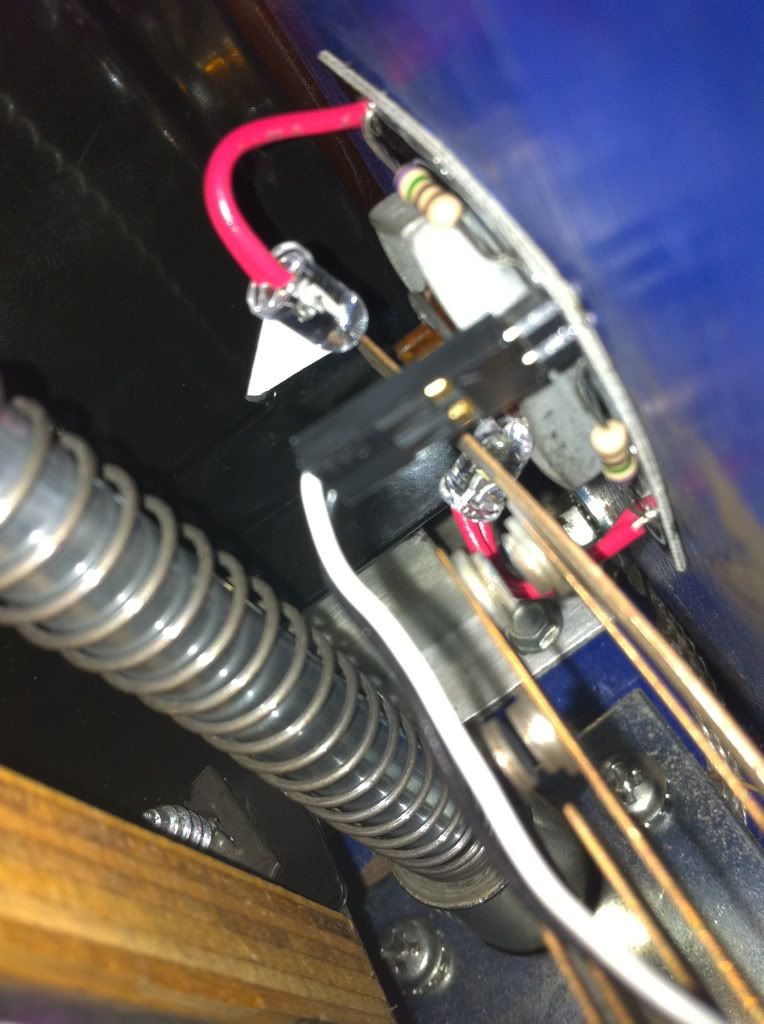
20131103_140343[1].jpgAnyone else having F106 randomly blow as a result of this mod? I have performed this modification twice (WH20 and TAF) with little success. My setup is identical to what is discussed in this post (using coindoor GI as the source for 6.3V). Unfortunately, F106 randomly blows (could be mins, hours, or even days). What the heck am I doing wrong on this mod? Thanks!
Quoted from xfassa:Anyone else having F106 randomly blow as a result of this mod? I have performed this modification twice (WH20 and TAF) with little success. My setup is identical to what is discussed in this post (using coindoor GI as the source for 6.3V). Unfortunately, F106 randomly blows (could be mins, hours, or even days). What the heck am I doing wrong on this mod? Thanks!
Shooter coil lead touching the right hand light fixture?
Quoted from xfassa:Anyone else having F106 randomly blow as a result of this mod? I have performed this modification twice (WH20 and TAF) with little success. My setup is identical to what is discussed in this post (using coindoor GI as the source for 6.3V). Unfortunately, F106 randomly blows (could be mins, hours, or even days). What the heck am I doing wrong on this mod? Thanks!
With the power off, clip on your meter leads to the circuit in diode mode and then launch some balls, bang on the flippers, see if you can get it to beep.
Will it blow if you don't have bulbs installed?
Is there one stray wire strand?
Is something touching the back of one of the LED heads at some point?
What if you knee the coin door?
Quoted from vid1900:With the power off, clip on your meter leads to the circuit in diode mode and then launch some balls, bang on the flippers, see if you can get it to beep.
Will it blow if you don't have bulbs installed?
Is there one stray wire strand?
Is something touching the back of one of the LED heads at some point?
What if you knee the coin door?
All excellent questions, however, this is happening on both machines that I installed the flipper button mod. No F106 issues on either machine prior to mod (or after removing mod). I switched the power source from the 6.3V coin door lights to an open 12V on the coin door controller board (and added a resistor). Everything "seems" to be working. Time will tell.....
Quoted from vid1900:Most coin doors have 2 or 3 lights that are GI (General Illumination) and are thus always on.
Tap power from any bulb. The one closest to the coin door hinge is usually the easiest.
I got me some sockets and LED bulbs now........
Can you just solder the wires onto the existing wire clamp that is already there on the coin door GI?? In other words, these wires slide onto a flat piece, they aren't simply soldered on - so can I solder onto the metal "clamp" portion once I slide the plastic protective cover off???
Thanks,
Nate
Quoted from Sc1f1:this is what I used on WH20, FH, EATPM and Tron
2 LEDS per button for $5 and even cheaper if you build it yourself
http://www.nicemite.com/LightmiteLB/LightmiteLB.htm
http://i1123.photobucket.com/albums/l552/sc1f1/P1040116.jpg
http://i1123.photobucket.com/albums/l552/sc1f1/f183af74.jpg
Going to show my still wetness behind the ears here.
Also, posted to the wrong thread... anyway...
Do I want 5v or 12v for the ones below?
Quoted from Pinball_Nate:I got me some sockets and LED bulbs now........
Can you just solder the wires onto the existing wire clamp that is already there on the coin door GI?? In other words, these wires slide onto a flat piece, they aren't simply soldered on - so can I solder onto the metal "clamp" portion once I slide the plastic protective cover off???
Thanks,
Nate
Show me a picture of a "wire clamp" you are considering.
Hey Vid, it's exactly like on the photo you posted showing the coin door connectors when you recommended using that as a power source, those "Y" type thingies that slide onto the other flat metal "-" thingies right at the coin slots to make them light up!
Technical huh?
Thanks,
Nate
I have had zero response to my post http://pinside.com/pinball/forum/topic/sttng-gun-feeder-hole-lighting. Since I am clearly desperate, is there someone on this thread who has some suggestions?
Vid, this is a beautiful mod, and I love it. One question.
I get that you are "tapping" into the wiring that goes into the coin door.
Here's my question: are you using T-taps to complete the circuit, or are you combining your lead wires for the flipper button lights with the GI lighting wires (basically, taking both wires, stripping the ends, combining their ends together, crimping a female lead on, and then plugging the female end to the male spade of the coin door light socket so both the coin door and the flipper button lights come on at the same time) ?
I've looked at everyone's pictures, but I don't think anyone has clearly shown the method they're using to tap the feed from the GI wiring to their flipper button's wiring.
Thanks guys!
Quoted from NPO:Here's my question: are you using T-taps to complete the circuit, or are you combining your lead wires for the flipper button lights with the GI lighting wires (basically, taking both wires, stripping the ends, combining their ends together, crimping a female lead on, and then plugging the female end to the male spade of the coin door light socket so both the coin door and the flipper button lights come on at the same time) ?
There are just so many different models of pins that there is no way to tell someone the "right" way to tap into the power.
I like clean and reversible, so Spade Splitters are a cheap solution.
Car audio guys love T-taps, another solution.
There may also be spare connectors on the coin for for Bill Acceptors or other lighting, so keep your eyes (and meter) open.
spade-splitter.jpg
T-Tap.jpgQuoted from NPO:I get that you are "tapping" into the wiring that goes into the coin door.
Here's my question: are you using T-taps to complete the circuit, or are you combining your lead wires for the flipper button lights with the GI lighting wires (basically, taking both wires, stripping the ends, combining their ends together, crimping a female lead on, and then plugging the female end to the male spade of the coin door light socket so both the coin door and the flipper button lights come on at the same time) ?
That's exactly my question - just a little more "clear!!" That makes sense, will have to get those spade splitters.
-Nate
Quoted from vid1900:There are just so many different models of pins that there is no way to tell someone the "right" way to tap into the power.
I like clean and reversible, so Spade Splitters are a cheap solution.
Car audio guys love T-taps, another solution.
There may also be spare connectors on the coin for for Bill Acceptors or other lighting, so keep your eyes (and meter) open.spade-splitter.jpg 13 KB
T-Tap.jpg 6 KB
Vid,
Do you have a link to those spade splitters? Google images is not finding them as you have them pictured.
Thanks,
RC
Quoted from lb1:I have had zero response to my post http://pinside.com/pinball/forum/topic/sttng-gun-feeder-hole-lighting. Since I am clearly desperate, is there someone on this thread who has some suggestions?
In case someone is interested:
http://pinside.com/pinball/forum/topic/sttng-gun-feeder-hole-lighting#post-1412368
Just did this to my STLE. I chose to go with red to go with the phaser/photon torpedo effect on the sides. The buttons I was able to get are transparent red and are Williams parts so they were a little large for the recessed hole they were to fit in. I chucked them up in my wood lathe and turned them down a bit to fit. Mounted 2 LEDs behind each and tapped into the start button so that in attract mode they flash with the start button but are on solid while playing. I used a pair of spade splitters on the start button, and made a pair of jumpers down to a connection block that stern used for a common connection point. The block has 3 connections on it but Stern only used 1, so I used the other 2.
I think it turned out really nice. But then again, I'm biased. ![]()
image-517.jpg
image-588.jpg
image-224.jpg
image-123.jpg
image-664.jpg
It looks orange in the photo, but it's actually red
image-743.jpg
Wanna join the discussion? Please sign in to reply to this topic.

Great to see you're enjoying Pinside! Did you know Pinside is able to run without any 3rd-party banners or ads, thanks to the support from our visitors? Please consider a donation to Pinside and get anext to your username to show for it! Or better yet, subscribe to Pinside+!

This page was printed from https://pinside.com/pinball/forum/topic/vids-guide-to-lighted-flipper-buttons-for-418/page/2?hl=exgametrader and we tried optimising it for printing. Some page elements may have been deliberately hidden.
Scan the QR code on the left to jump to the URL this document was printed from.
 Philadelphia, PA
 Pickering, ON