(Topic ID: 35965)

Vid's Guide - Bally/Stern Driver Board Repair / Bulletproofing.

By vid1900

11 years ago


Topic Heartbeat

Topic Stats

  • 224 posts
  • 67 Pinsiders participating
  • Latest reply 10 months ago by La4s
  • Topic is favorited by 388 Pinsiders

You

Linked Games

Topic Gallery

View topic image gallery

Phantasm-1-660x330 (resized).jpg
821B6806-6392-47B6-9600-844F1AF53019 (resized).jpeg
0E84508E-1712-40E8-8713-9CCFE75BC37E (resized).jpeg
LostWorld_Rectifier_Wiring.png
B8BF7E6E-1F96-4C77-834F-AA95932C25E6 (resized).jpeg
20181220_112338 (resized).jpg
IMG_0021 (resized).JPG
IMG_0020 (resized).JPG
IMG_0656 (resized).PNG
IMG_0202 (resized).JPG
IMG_0201 (resized).JPG
IMG_0203 (resized).JPG
IMG_0195 (resized).JPG
IMG_0197 (resized).JPG
IMG_0200 (resized).JPG
IMG_0198 (resized).JPG

Topic index (key posts)

3 key posts have been marked in this topic (Show topic index)

There are 224 posts in this topic. You are on page 2 of 5.
#51 10 years ago

Thanks! I just replaced it as my old one did not look like that tantalum you pictured. It was just a silver colored electrolytic cylinder style. I guess the replacement I just put in is also just an electrolytic. Does that cap further stabilize the 5V to the CPU?

I'll let you know if I notice any further difference.

Thanks once again!

1 week later
#52 10 years ago

Well it's been a week and the new caps didn't seem to make a difference. When I first start up the game I usually always have some sort of intermittent problems but they are not always the same. Sometimes it just doesn't boot. Will turn off and on a few times and then it will boot OK. Then maybe after a few minutes it goes dead again. GI stays lit but scores and controlled lights go dead. Again turn off and on and will usually boot up again fine. I've had another few strange things happen also. Game boots up and after a few minutes it goes into what seems to be similar to one of the test modes. Either all controlled lights will flash, or the solenoids start to fire randomly, or the scores go crazy, or it starts to play single notes from the sound board. Also had the flippers just go dead. But if I power down and then back on all is fine again.

These problems seem to go away after the game has been on for about 15 minutes. Game then seems to stay pretty stable for many hours after that. Also if you get right into playing the game after start up most of the time it's all good but I have had some of these problems pop up right in the middle of a game during those first 15 minutes or so.

I've done all the ground mods on the main board and the solenoid/power board. Did not do any work on the BR board but voltages seem to be OK. Luckily main board has no battery damage although it still has the brown chip holders. Changed the battery to a capacitor. Also did not replace any connectors but did clean them all.

I figure my problem may be a faulty BR giving intermittent unstable voltages. I do see the GI lights flicker and dim every so often. Or just some bad intermittent connectors. Or problem with the chip sockets and/or traces on the main board.

Any ideas as what may be causing these strange problems? Why would powering down and then start up again make them go away? Why would the game become more stable after being on for about 15 minutes?

Any suggestions would be greatly appreciated. I would like to get this pin to be rock solid if at all possible. Luckily it tends to play just fine after those first 15 minutes.

Thanks again!!

#53 10 years ago

So, may I recommend a couple of bars near my house? My Taxi is acting up...

-Steve

#54 10 years ago
Quoted from Jags:

Or problem with the chip sockets and/or traces on the main board.

When the game IS running correctly, twist the chips in their sockets and see if the game locks up.

If you put your finger under one end of the chip, can you pull it out? It should take a screwdriver to lift a chip from a good socket.

#55 10 years ago
Quoted from vid1900:

When the game IS running correctly, twist the chips in their sockets and see if the game locks up.

Ok did that. The game did go dead when I gave a twist to the U2 ROM chip. Powered down and then back up and everything is back to normal. Did not reseat the chip as the twist may have been all that's needed. I will keep an eye on that chip. If the machine crashes again in any way I will remove and reseat that chip. Slowly and systematically is probably the best way to go about finding the culprit!

Thanks again for the help!!

#56 10 years ago
Quoted from Jags:

The game did go dead when I gave a twist to the U2 ROM chip. Powered down and then back up and everything is back to normal. Did not reseat the chip as the twist may have been all that's needed.

You need a new socket on U2.

#57 10 years ago

Why tantalum over electrolytic? I have had a few catastrophic tant cap failures. Almost got hit in the face by one shorting and blowing on a cheap squeek.

#58 10 years ago

Tantalum caps are much more stable and have low ESR and very low leakage.

Most electrolytic have a 7-10 year rated life, Tants have 50 year.

As you have found, Tants hit with overvoltage spikes can go into thermal runaway (aka fire).

#59 10 years ago
Quoted from Jags:

still has the brown chip holders

This is your problem. Those brown sockets suck, and your game will probably not work reliably until they are all replaced.

#60 10 years ago

I agree with Ken. Those sockets are junk and need replaced or you will have issues in the future. Message me if you need help changing sockets and rebuilding the board.

#61 10 years ago

Thanks for all the advice and yes replacing the sockets is definitely on the list. Where would be the best source to get some good sockets. Here in Hawaii you really can't get anything like that locally except for Radio Shack. And as we all know most of the Radio Shack stuff is all low quality junk also.

Let me know. Thanks!

#62 10 years ago

Great Plains Electronics. I know they ship USPS and that shouldn't be too bad to Hawaii.

I recommend this style of socket.
http://www.greatplainselectronics.com/products.asp?cat=162

*edit*
Ahh well i guess GPE isnt stocking 24 and 40pin sockets in the twin leaf style. Use the machine pin ones from his site. They are fine, I just prefer the other style.

#63 10 years ago

Another great place for sockets (and they are probably closer to you than GPE - j/k) is Tayda:

http://www.taydaelectronics.com/connectors-sockets/sockets/sip-sockets.html

#64 10 years ago

BTW: never order from Tayda without checking their facebook for a further 15% off your order:

https://www.facebook.com/TaydaElectronics

#65 10 years ago

Tayda is a great supplier. I use them for a lot of things including IC sockets.

7 months later
#66 10 years ago

UPDATE:

So the same customer calls me and says now his game runs about 15 minutes and then the displays all go crazy, about 5 minutes after that, the game crashes.

Of course, I'm rarely in the state he lives in so, I've been unable to stop by and help him, but this week I have work in his area.

I assume it is a connector/socket issue by his description, but I first check that the voltages are correct and clean on the MPU board. They are all correct.

#67 10 years ago

I want to bulletproof the whole board so I can avoid any other callbacks.

Job one: get rid of these old and tarnished connectors.

You can see that they have been sanded many times over the years to try and clean off the oxidation.

1.jpg1.jpg

#68 10 years ago

Since I'm on the road, I have to use my Hakko desoldering gun rather than my benchtop Metcal. The Hakko makes quick work of removing the old connectors.

Note that I leave the "key" position full of solder - you can't make a mistake that way and leave a pin in the new connector housing.

2.jpg2.jpg

#69 10 years ago

The old Bally connectors were about as crappy as you can get.

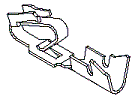
The new ones are much more robust and have a backing spring finger that puts positive pressure on the female part of the connector, locking it in place.

These better connectors are 2 cents more expensive than the originals, and are cut to any needed length - no need to to stock a bunch of different pinned connectors.

I pulled the Key pin out with a pair of needle nose pliers, and soldered the connector in.

3.jpg3.jpg

#70 10 years ago

Next, all the old IC sockets were removed.

Some of them were so weak that I could pry up one end of the chip with my fingers (normally you need a flat screwdriver to remove a chip).

I replaced all the sockets with SIP sockets. SIPs are cut to any length, so you don't have to keep a ton of different IC sockets in your inventory. SIPs have an amazingly strong grip on the chips, you are not going to pull any chips out by hand - that's for sure.

4.jpg4.jpg
SIP_Socket_2.jpgSIP_Socket_2.jpg

#71 10 years ago

After soldering, make sure you clean up all the flux with Alcohol or Naphtha.

It is a sign of good workmanship, and it keeps the flux from further corroding the board, or high voltage arcing.

FLUX.jpgFLUX.jpg

#72 10 years ago

Finally I replaced the battery holder with a remote unit and replaced the female connectors on the wiring harness.

I powered up the game and it ran flawlessly for over an hour.

This MPU is now bulletproofed.

5.jpg5.jpg
3 months later
#73 9 years ago

Nothing better than a good Vid thread. Great stuff here.

2 months later
#74 9 years ago

Hey Vid,

My local electronics store sells capacitors for cheap, but only had certain ones in stock.

Would 12000uF @ 50v and 150uF @ 450v work for C23 and C26? Thanks in advance.

IMG_20140808_141126_003.jpgIMG_20140808_141126_003.jpg
#75 9 years ago
Quoted from goldiewag:

Would 12000uF @ 50v and 150uF @ 450v work for C23 and C26? Thanks in advance.

Yes.

The orig was 11,000uf 20v, and 150uf 350v.

If the game has 3 or more flippers, then bump up to 15,000uf 20v

#76 9 years ago

Thanks for the reply! Wasn't sure if the 50v capacitor would be overkill or not. Guess I'll give 'em a shot and see how they do.

#77 9 years ago
Quoted from vid1900:

Next, all the old IC sockets were removed.
Some of them were so weak that I could pry up one end of the chip with my fingers (normally you need a flat screwdriver to remove a chip).
I replaced all the sockets with SIP sockets. SIPs are cut to any length, so you don't have to keep a ton of different IC sockets in your inventory. SIPs have an amazingly strong grip on the chips, you are not going to pull any chips out by hand - that's for sure.

4.jpg 120 KB

SIP_Socket_2.jpg 4 KB

What's your take on machine pin socket vs twin leaf?

I've been using machine pin sockets for years. I stock all sizes, along with enough SIP strips in case I run out of something, or for the rare case I get something mangled to the point where I really need easy access to all the socket pins.

But, a few trusted techs have told me lately that they've gone back to twin leaf sockets, because the SIP sockets are really only a stronger bond for maybe 1-2 insertions, and that the leads of ICs 'cut' into the round machined sockets, so after 1-2 insertions, the SIP sockets are starting to wear out.

I'm undecided at this point... I did pick up some twin leaf sockets, and used them on a few boards, and had decent luck...

#78 9 years ago
Quoted from johnwartjr:

after 1-2 insertions, the SIP sockets are starting to wear out.

Sounds like some nice folklore.

The machine pin sockets we use at work are rated for 1000 insertion cycles.

Even the bargain 3M ones claim 500 cycles.

If a socket is wearing out after 1 or 2 insertion/removal cycles, it is clearly defective (or is plated with an incompatible material ). Even the friggin' SCANBEs were better than that, lol.

#79 9 years ago

as usual. Thanks Vid for all of your expertise.

#80 9 years ago
Quoted from johnwartjr:

What's your take on machine pin socket vs twin leaf?
I've been using machine pin sockets for years. I stock all sizes, along with enough SIP strips in case I run out of something, or for the rare case I get something mangled to the point where I really need easy access to all the socket pins.
But, a few trusted techs have told me lately that they've gone back to twin leaf sockets, because the SIP sockets are really only a stronger bond for maybe 1-2 insertions, and that the leads of ICs 'cut' into the round machined sockets, so after 1-2 insertions, the SIP sockets are starting to wear out.
I'm undecided at this point... I did pick up some twin leaf sockets, and used them on a few boards, and had decent luck...

I agree SIP sockets kind of suck. They feel like they lose tension after a few cycles. I only use them in odd socket shapes, like a 5101. Maybe i got bad chinese ones.

I like the dual leaf sockets tayda sells. I have installed countless numbers of them with no issues. Sockets can be kind of pricey but for 9 cents... these are good.

http://www.taydaelectronics.com/connectors-sockets/sockets/dip-sockets/24-pin-dip-ic-socket-adaptor-solder-type-0-6.html

2 months later
#81 9 years ago

CLASSIC STERN SDU-100

================================

This Stern SDU-100 was found installed in a Bally EBD.

The game had working GI, but nothing else.

Because Classic Stern licensed the Bally pinball architecture, you could interchange most of the boards - including this Power/Solenoid board.

The SDU-100 is basically the older Bally P/S design with some differences in circuit layout because the board is double sided and has a "hand drawn" style layout.

Because it is a version of the oldest Bally design, the High Voltage display section is unfused.

We are going to bulletproof this board, and update the HV section with a fuse (by adding the fuse I guess we make this board into a poor-man's SDU-100c).

#82 9 years ago

This board has seen a hard life and any work done on it was of very poor quality.

SDU-100.jpgSDU-100.jpg

#83 9 years ago

If you have only ever seen a Bally solenoid board, the backside of the Stern board looks rather alien and hand drawn.

Lots of lifted traces from poor solder work on this board.

IMG_0252.jpgIMG_0252.jpg

#84 9 years ago

From earlier in this guide, you know that we automatically replace those two old caps.

The sticker on this board says it came from a Nugent, and the date on the one GE cap was 1975. So yeah, I don't feel bad at all tossing some 40 year old caps in the trash.

C23 can be anywhere from 11,000uf - 15,000uf, but if the game has more than 2 flippers, choose the 15,000uf. 25v is a common size, but you can put in a higher voltage rated part and it would make the cap last even longer.

C26 I've pulled out factory parts from 150uf - 180uf 350v. Again, higher voltage rated parts will generally last longer.

C23 https://www.greatplainselectronics.com/proddetail.asp?prod=CER-15000uF-25V

C26 https://www.greatplainselectronics.com/proddetail.asp?prod=CEA-150uF-350V-RMD

-

Newer Bally driver boards have the High Voltage section fused in the marked area.

No-HV-fuse.jpgNo-HV-fuse.jpg

#85 9 years ago

By holding the circuit board up to the light, we can see that there is plenty of room to install a HV fuse.

HV-TRACE-SHOWN.jpgHV-TRACE-SHOWN.jpg

I know some of you are saying to yourself that there are no through-plated holes to mount a fuse clip. That is true, but we will use a trick called Shunting to neatly and securely mount a fuse to the existing board.

You will need:

2 fuse clips 1A1907-06: https://www.greatplainselectronics.com/products.asp?cat=32

1 3/16A fast blow fuse: https://www.greatplainselectronics.com/products.asp?cat=124

1 Scrap of wire

2 Square Pins that you removed from the Male .156 connectors when you polarized them.

1A190706.jpg1A190706.jpg

#86 9 years ago

Here is our HV trace that will be cut and fused.

HV-TRACE-REAR.jpgHV-TRACE-REAR.jpg

#87 9 years ago

The Bally boards have a tiny, hard to find, expensive fuse on them.

We have lots of room, so we are going to use a full size (1.25"), easy to find, cheap fuse.

1. Hold the board up to a lamp and figure out where the fuse has to go.

2. Assemble a fuse between 2 Fuse Clips so you can get your hole dimensions correct.

3. Using the assembled fuse, line up the Fuse clip so the top stud of the bottom clip will be soldered to the HV trace. Mark off the locations of your 4 holes.

4. Using a small 1.5mm drill bit, drill your Fuse mounting holes.

5. Using a razor blade, cut the high voltage trace to the left of the Fuse Clip hole.

6. Scrape away the insulation coatings on each side of the cut trace.

PREP-FOR-FUSE.jpgPREP-FOR-FUSE.jpg

FUES-ASSEMBY.jpgFUES-ASSEMBY.jpg

#88 9 years ago

Leaving the fuse between the 2 clips, install it from the front side.

Solder your two shunts across the Fuse Clip studs, while holding the clips tight to the board. The clips are going to get HOT, so wear a leather glove.

When the solder cools, you will find that the clips are solidly mounted, even with no through plated holes.

Using the scrap of wire, jump the cut trace to the open end of the fuse.

This completes the HV circuit again.

FUSE-CIRCUIT.jpgFUSE-CIRCUIT.jpg

#89 9 years ago

Here is a list of the minimum bulletproofing needed for a Classic Stern board on the front side:

1. Replace C26 and C23 Caps. These always have to go if they are the silver originals, or if more than 10 years old since being replaced.

2. Add 3/16 amp fuse protection for HV.

3. Replace .156" male pin connectors. These are always tarnished with broken solder joints. They are so cheap, it's not worth trying to clean or resolder them.

4. Replace .1" male pin connectors. These are even worse than the .156" connectors. Trash 'em.

5. Upon first time powering up the board, remember to set the HV to +170V (or lower if the displays will stay lit) using the little thumb wheel in the HV circuit. The lower the voltage, the longer the displays will last.

The only exception to this rule is if you have installed BRAND NEW display glass; because new displays will probably require +190V for a few hours until they break themselves in. After a few hours of play, turn the HV back down to +170V (or lower).

Remember this is high voltage - use care!

BULLETPROOF-FRONT.jpgBULLETPROOF-FRONT.jpg

That fuse holder almost looks like it belongs there, yes?

#90 9 years ago

On the back we always need to:

1. Tie C23's Negative lead to ground. Use a short length of insulated wire.

2. Tie C26's Negative lead to ground. This can be done with the excess leg from the new cap - so don't trim it until you tie it in.

3. Tie Test Point #1 to Test Point #3.

4. Repair any missing traces or damaged foil.

BULLETPROOF-BACK.jpgBULLETPROOF-BACK.jpg

#91 9 years ago

Pinwiki is great, but nothing helps better than really good hi-res photos for anyone in question with what they are about to do. Great work Vid.

#92 9 years ago

The HV fuse on the driver board is kind of goofy. I dont add it into the early driver boards because it doesnt blow when the HV regulation section shorts. The fuse on the rectifier board blows when the bridge shorts. Couldn't they just put a smaller fuse on the rectifier board....? i guess the rectifier board fuse is to just protect for the rectifier diodes shorting, but 1amp fuse is still going to protect any kind of catastrophic short at a display. I bet you can put a quarter or half amp fuse on the rectifier board and never have problems... i might try that.

#93 9 years ago
Quoted from barakandl:

The HV fuse on the driver board is kind of goofy.

I have maybe only replaced 25 of those fuses in my entire life, but those times that they did trip are good enough reason for me to spend .75 cents and add the protection to the old driver boards too.

I've seen so many boards with 1/4 amp fuses installed, that I wonder if the factory used them occasionally?

#94 9 years ago
Quoted from vid1900:

The old Bally connectors were about as crappy as you can get.
The new ones are much more robust and have a backing spring finger that puts positive pressure on the female part of the connector, locking it in place.
These better connectors are 2 cents more expensive than the originals, and are cut to any needed length - no need to to stock a bunch of different pinned connectors.
I pulled the Key pin out with a pair of needle nose pliers, and soldered the connector in.

3.jpg 72 KB

Hey Vid, where do you get positive pressure type of connector? It might be me, but I couldn't tell from the picture exactly what they look like. Any additional info on these connectors would be appreciated.

#95 9 years ago
Quoted from BallyPinWiz:

Hey Vid, where do you get positive pressure type of connector?

You can get them from GPE:

https://www.greatplainselectronics.com/proddetail.asp?prod=26-48-1245

Or from Tayda (although Tayda's style can change on a whim):

http://www.taydaelectronics.com/connectors-sockets/wafer-housing-crimp-terminal/serie-2500-2-54mm.html

2 months later
#96 9 years ago

BULLETPROOFING EARLY BALLY RECTIFIER BOARDS

====================================================

These -18 boards were used until about 1980 and are always trashed and hacked.

The rectifiers used by bally were grossly undersized amperage wise, and replacing a single unit required precision soldering skills. If you did not get the new rectifier lined up with the other two units, it would prevent them from making solid contact with the heat sink - burning them all out even faster. (the board in the picture had a rectifier replaced and the tech put it on top of the board, rather than try to align it with the other rectifiers on the bottom of the board).

The connector pins would oxidize and finally melt the solder off the circuit board as the resistance increased. The connector would often get so hot it would burn itself in half, and the desperate tech would solder the pin's wire directly to the test point!

The diodes were undersized, the fuse clips will be burnt and no longer tightly tempered.

A big mess.

So big of a mess, that many people just choose to replace the entire board with a brand new design.

At $55 for a brand new Rottendog BPS018, replacement is not a bad option. If you choose to replace your board, remember to move one transformer wire at a time! Don't just clip all the wires and then drive yourself crazy finding their proper location on the new board. I warned you.

1.jpg1.jpg

#97 9 years ago

I've never seen a board with good pins. They are always corroded and burnt.

Don't try and sand or polish those burnt pins, they 100% of the time need to be replaced. <--read this again until it sinks in.

Don't take any shortcuts here, get good Molex brand square pins.

The female connectors will have to be replaced too. No sense chewing up your brand new shiny male pins with abrasively burnt female connectors. Again, these connectors carry so much current, that you can't take shortcuts - use Trifurcon female connectors. The Trifurcon connectors have little side wings that double the amount of conducting surface area.

https://www.greatplainselectronics.com/proddetail.asp?prod=26-48-1245

2.jpg2.jpg

156 header.jpg156 header.jpg

Trifurcon.gifTrifurcon.gif

#98 9 years ago

When the J3 female connector burns itself in half, lazy techs will solder the 12v wire directly to the TP3 test point. No, I'm not kidding, I see it all the time.

Put this wire back into the female connector J3 at position #8, when you rebuild the connector.

3.jpg3.jpg

#99 9 years ago

These 1n4004 diodes supply the high voltage displays.

If the game instantly blows F2 upon powerup, one of these diodes is the likely culprit.

Replace them with higher rated 1n4007 diodes, and mount them leaving a little space between the component and circuit board for airflow.

4.jpg4.jpg
#100 9 years ago

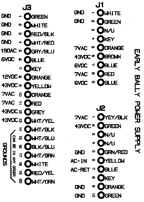
Here is a great diagram of the board pinout stolen from Tom Callahan.

http://pin-logic.com/

5 Tom Callahan Pinout Bally .gif5 Tom Callahan Pinout Bally .gif

Promoted items from Pinside Marketplace and Pinside Shops!
From: $ 169.00
$ 10.95
Eproms
Pinballrom
 
$ 11.00
Electronics
Third Coast Pinball
 
$ 10.00
$ 12.00
Electronics
Yorktown Arcade Supply
 
$ 69.00
$ 18.95
Eproms
Pinballrom
 
$ 55.00
Displays
PinballSolutions.eu
 
$ 18.00
Electronics
Yorktown Arcade Supply
 
Great pinball charity
Pinball Edu
There are 224 posts in this topic. You are on page 2 of 5.

Reply

Wanna join the discussion? Please sign in to reply to this topic.

Hey there! Welcome to Pinside!

Donate to Pinside

Great to see you're enjoying Pinside! Did you know Pinside is able to run without any 3rd-party banners or ads, thanks to the support from our visitors? Please consider a donation to Pinside and get anext to your username to show for it! Or better yet, subscribe to Pinside+!


This page was printed from https://pinside.com/pinball/forum/topic/vids-guide-quick-bally-driver-board-repair-bulletproofing/page/2?hl=randy_g and we tried optimising it for printing. Some page elements may have been deliberately hidden.

Scan the QR code on the left to jump to the URL this document was printed from.