(Topic ID: 135409)

TOM Trunk Error - Leon's Fix. NOW AVAILABLE, SEE POST #225

By EvanDickson

8 years ago


Topic Heartbeat

Topic Stats

  • 807 posts
  • 215 Pinsiders participating
  • Latest reply 9 months ago by gizmo33
  • Topic is favorited by 68 Pinsiders

You

Linked Games

Topic Gallery

View topic image gallery

Sans titre (resized).jpg
trunk wire (resized).png
B8989610-FE1D-411F-8A39-0917BA32624E (resized).jpeg
20190217_124203 (resized).jpg
IMG_5877 (resized).JPG
image (resized).jpg
Trunk Opto Board Cable (resized).JPG
Cable (resized).jpg
20181208_130847 (resized).jpg
20181208_130824 (resized).jpg
20181208_130808 (resized).jpg
20181123_121557 (resized).jpg
20181123_115252 (resized).jpg
ToM 6 Billion (resized).jpg
20180224_195318 (resized).jpg
mould.pdf (PDF preview)

Topic index (key posts)

18 key posts have been marked in this topic, showing the first 10 items.

Display key post list sorted by: Post date | Keypost summary | User name

Post #128 Schematics Posted by german-pinball (8 years ago)

Post #131 Prototype Posted by german-pinball (8 years ago)

Post #133 Animated installation guide for prototype Posted by german-pinball (8 years ago)

Post #145 Prototype photos & video Posted by german-pinball (8 years ago)

Post #146 Trunk opto board prototype Posted by german-pinball (8 years ago)

Post #210 PCB layouts Posted by german-pinball (8 years ago)

Post #225 Opto board replacements, pricing, and shipping info Posted by german-pinball (8 years ago)

Post #242 Opto Board PCBs Posted by german-pinball (8 years ago)

Post #359 Photos of populated boards Posted by german-pinball (8 years ago)

Post #372 Photo of installed board Posted by german-pinball (8 years ago)


Topic indices are generated from key posts and maintained by Pinside Editors. For more information, or to become an editor yourself read this post!

You're currently viewing posts by Pinsider german-pinball.
Click here to go back to viewing the entire thread.

#9 8 years ago

Here is a linkt to the datasheet of the relay:

http://www.datasheetarchive.com/dlmain/Datasheets-20/DSA-388631.pdf

As said, the relay is oversized - this one is not so expensive:

http://www.mouser.de/search/ProductDetail.aspx?Omron-Electronics%2fG5LE-1-VD-DC24%2f&qs=JK6Bpmia%2fmst%2fmdz7nyVOw%3d%3d

Important: Do not forget a flybackdiode over the relais coil!!!! It looks, as Leon forget this.

#10 8 years ago

In a hurry I designed the little PCB. I could etch you a little board and ship to you.

If someone could verify. would be good.

Here is the layout:

Board.JPGBoard.JPG

The board could look like this:

Board 1.JPGBoard 1.JPG

#11 8 years ago

Perhaps this might help you a bit

tom schem.JPGtom schem.JPG

#12 8 years ago

You can even make it better. Why use the two 0,156 pin-headers. Imho it is easier, to solder 2 wires direct to the motor. So you are also more flexible where mounting the new pcb, e.g. near to the eddy-board.

Here we go - 3rd board is my suggestion with another smaller relay:

layout alternative.JPGlayout alternative.JPG

#14 8 years ago
Quoted from canea:

Very interested in this board fix. Let us know updates when you have them - would love to have one of these myself.

The idea is form Leon (RIP) - a really great guy form belgium.

I only made the new layout, to help EvanDickson, the thread starter.
But unfortunately there came no response.

Only thing, I can offer you, is to etch you a board and put all parts on it - if you want.

I thought about the design a bit and made a new design. I do not like the way, Leon fastens the new PCB to the trunk-opto-pcb with only 1 screw. In my new design, you use both upper srews of the trunk-opto-pcb. I alsi rearragned the connectors, so connecting the cables is more easy and fits better imho.

Unfortunately I do not have a TOM for testing.

But fotos say more than words.

NEW Design single.JPGNEW Design single.JPG

NEW Design.JPGNEW Design.JPG

#16 8 years ago
Quoted from njgsx96:

I would definitely be interested in this as my TOM has the same issue.

OK, no probelm for me, to make 1 or 2 boards.

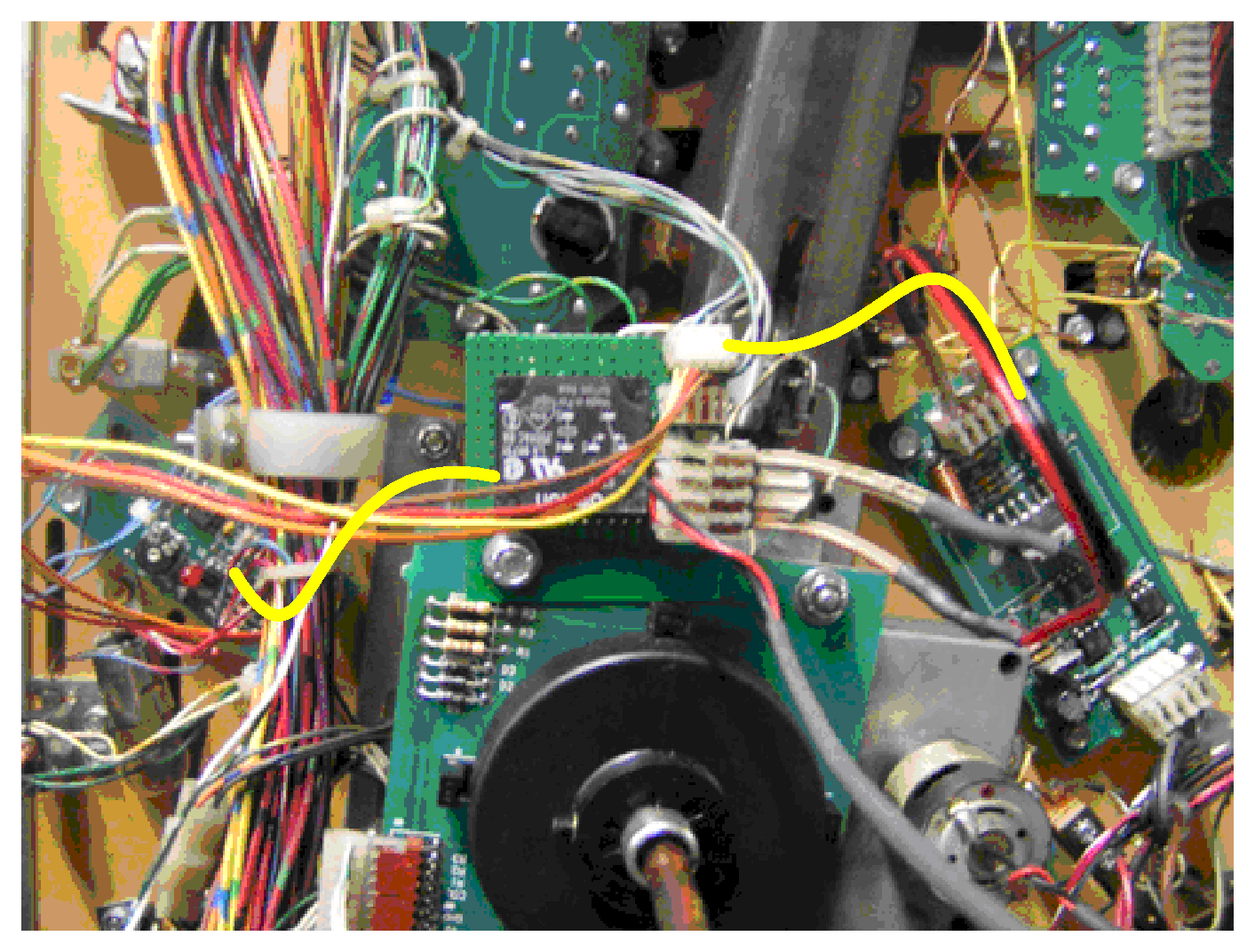
But you could do me a favour. Please measure the length for the 2 new cables. As said, I do not have a TOM. In the following foto I need the length of the 2 yellow marked cables. Please take a wire and measure a comortable lenghth, not too long but also not too short.

Wire length.GIFWire length.GIF

#19 8 years ago

OK, I will make 4 boards, but please do the following measurments for me:

please measure.GIFplease measure.GIF

#28 8 years ago

Here is the final board. I will etch it this weekend.

magic magic trunk.JPGmagic magic trunk.JPG

#34 8 years ago
Quoted from EvanDickson:

Hey, this thread really took off since I thought it was resolved. A specific board, that's awesome, German-Pinball. And I love that the required parts are labelled on the board! Any idea on the cost of the product?
Thanks,
Evan

As there are so many interests, I have decided, to finally let produce professional boards. But at first, I will etch this weekend the prototype and send it to "canea" for testing.

The more boards I let produce, the lower the costs for each pcb:

10 pieces / 12,00 USD/each
20 pieces / 6,00 USD/each
30 pieces / 5,50 USD/each
50 pieces / 3,60 USD/each

The rest are the molex connectors, the relay and 1m=42,5inches wire.

Depending on how much pcbs I let produce, I think, the price for ALL parts will be about 12-18 USD.

As far as I see, we now have 10 intersted people - 20 would be good, then the price for each pcb is the half compared to 10.

If I ship the spare board only, you should take yourself care about to get the parts with, but have extra shipping costs from the parts distributor or so. Best would be, I get all parts, so the set is complete and I ship as a DIY-project or complete assembeld, as desired.

- Ingo

PS.:
What is with the control-LEDs? Are these desired??

How thick are the wires, AWG20 ????

#35 8 years ago
Quoted from zaza:

Hold on a sec.
Am I correct that this PCB is connected to the exit of the BI-DIRECTIONAL motor control PCB A-16120 ?
If so, then I would suggest not to install D1, the L6203 would not like that.
LeonsRIPMMTB TEH fix.jpg

Thanks for the hint, I will check it!!!

#41 8 years ago
Quoted from zaza:

Hold on a sec.
Am I correct that this PCB is connected to the exit of the BI-DIRECTIONAL motor control PCB A-16120 ?
If so, then I would suggest not to install D1, the L6203 would not like that.
LeonsRIPMMTB TEH fix.jpg

@zaza:
You are absolute correct, it is connected to the BI-DIRECTIONAL pcb A-16120 and the L6203 would not like that

What do you think of the following solution, so we have an effective back emf protection for motor + relay-coil??

BACK EMF protection.JPGBACK EMF protection.JPG

#45 8 years ago
Quoted from zaza:

If Leon's modification worked without a diode, then the L6203 is likely protected against voltage spike.
In the L6203 datasheet there are 2 diodes per channel so it looks like it won't need external diodes.
Maybe someone with knowledge about electronic components can give a more decisive answer.
6203-1.JPG

@zaza:

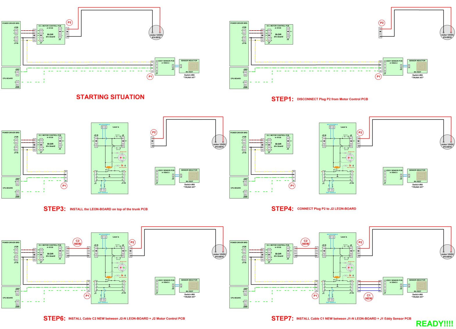
Thanks.

Yes, Leon´s mode worked without diodes, but we want the absolut perfect layout.

Your excerpt from the datasheet show the 2 inner diodes work as freewheel-diodes, so that there is protection against cross conduction.

But datasheet also says "Although the device is protected against cross conduction, current spikes can appear on the current sense pin due to charge/discharge phenomena in the intrinsic source drain capacitances".

So EXTERNAL freewheeling diodes would prevent current flow through Rsense and relocate power dissipation to "outside".

Same datasheet shows this with external diodes:

external freewheel diodes.JPGexternal freewheel diodes.JPG

Here, they are also shown:
http://mech.vub.ac.be/teaching/info/mechatronica/finished_projects_2010/groep2/electro.html

I am a bit unsure now, but ihmo, these diodes are not absolutly necessary, but it doesn´t hurt to have them (we would have additional protection). And as we are in modern times in these days I would not use good old BYW-Diodes, but schottky diodes e.g. SB3100.

But we will see, when the prototype is etched, we can test with and witout diodes.

#54 8 years ago

Here is the list:

njgsx96
DavidPinballWizz
Magicchiz
canea
lyzanxia
CraigC
MMP
bstyles
Rum-Z
EvanDickson
Kiwipinhead
DB62
Out-West
PinBallMagician
jsa (2)
rotordave
EternalLife
Bskinner46
Q-Dog

#64 8 years ago

Updated list:

njgsx96
DavidPinballWizz
Magicchiz
canea
lyzanxia

CraigC
MMP
bstyles (2x)
Rum-Z
EvanDickson

Kiwipinhead
DB62
Out-West
PinBallMagician
jsa (2x)

rotordave
EternalLife
Bskinner46
Q-Dog
kungfucop

MT45
Atomicboy

#70 8 years ago

Updated list:
njgsx96
DavidPinballWizz
Magicchiz
canea
lyzanxia
CraigC
MMP
bstyles (2x)
Rum-Z
EvanDickson
Kiwipinhead
DB62
Out-West
PinBallMagician
jsa (2x)
rotordave
EternalLife
Bskinner46
Q-Dog
kungfucop
MT458
Atomicboy
mwong168 (4x)
reynolds531
xfassa
cal50

I will show you the etched prototype board tomorrow morning.

#83 8 years ago

This is the always UP-TO-DATE List:

njgsx96 (*)
Magicchiz (*)
canea (*)
lyzanxia (*)
CraigC (*)
MMP
bstyles (2x) (*)
Rum-Z (*)
EvanDickson (*)
Kiwipinhead
DB62 (*)
Out-West (*)
PinBallMagician (*)
jsa (2x) (*)
rotordave (*)
EternalLife (*)
Bskinner46 (*)
Q-Dog (*)
kungfucop (*)
MT458
Atomicboy (*)
mwong168 (6x) (*)
reynolds531
xfassa
cal50 (*)
markmon
TowMater
gliebig (*)
Mank (*)
Eddie (2x) (*)
lyonsden (*)
schonb25 (*)
Skypilot (*)
Ranhorton (*)
mjfisher (*)
RVH
mamemaster
kmoore88
Methos
Gotpins (*)
chriskd (*)
Latinfantom
wimpinball (5x)
MSN22
RobertWinter (*)
Mhulsebu (*)
not4tilts (*)
rcarlson (4x) (*)
2manypins
DallasPinball (*)
Trooper11040
Spencer
angus
blueman01 (2x) (*)
Radius118 (*)
PittPin (*)
flugs (*)
pinballinreno (*)
MnHotRod (*)
larrys1 (*)
Starwriter (*) (*)
Sijcolo (*)
macci (*)
dgarrett (*)
jeppepupu (*)
tonycip (*)
Pinballflare (*)
JoeGrenuk (*)
epthegeek (*)
msj2222 (*)
FreeBee (*)
littlecammi (*)
Trifle (*)
ikaruga007 (*)
GreenMachine19 (*)
winslow (*)
gordonbowar (*)(*)
nightsearcher (*)
Chemixtry (*)
johnbtcb (*)
Jvspin (*)
jk (*)
hedghog (*)
oscarspa (*)
RandomKG (*)
orbian (*) (*)
dMode (*)
Wisconsinpinball
kse001 (*)
Beeble (*)
CHighfill (*)
Malibu-SS (*)
tomterlec (*)
dudah (*)
bhwolf (*)
MikeHogue (*)
pinfrank76 (*)
flashman (*)
okletsgo (*)
burtcam (*)
JosiahCox
PinballHelp (*)
mtdouble (*)
marcelmagic (*)
Bantam (*)
ibuypinballs (*)
nickbuol (*)
Bramvk (*)
Skarv (*)
....
krunch (*)
meSz (*)
ski1game2 (*)
aruaKcalb (*)
roc-noc (*)
...
Genetic2000 (*)
tomtest (*)
volkdrive (*)
Mtg381 (*)
mdclips (*)
...
grs57f (*)
SFEastBayDave (*)
caylegeorge (*)
nd4spd (*)
sirlonzelot (*)
...
Tensikka (*)
NoMonkey (*)
nibre (*)
JOETECH (*)
indypinhead (*)
...
pinjunky (*)
Goalie (*)

ALL SHIPPED

++++++++++

jyeakley (*)

#87 8 years ago

Here is the etched prototype-pcb.

Tomorrow I will cut the outlines and drill the holes, in 2 days, the parts should arrive and the the proto goes to canea.

Here we go:

Proto PCB 1-min.JPGProto PCB 1-min.JPG

Proto PCB 2-min.JPGProto PCB 2-min.JPG

proto xxx.JPGproto xxx.JPG

As you can see, on this proto I have forseen a few jumpers, so canea can do his tests with the layout of Leon and additionally switch the LEDs individually and switch the flyback diodes.

#90 8 years ago
Quoted from zaza:

BI-DIRECTIONAL motor control

@zaza:

I have routed the prototype like this.

leon TOM diodes.JPGleon TOM diodes.JPG

Any reservations? If yes, please tell me why.

#91 8 years ago

@all:

Here is HOW IT WORKS - pretty simple, isn´t it?

Motor off.JPGMotor off.JPG

Motor on.JPGMotor on.JPG

#97 8 years ago
Quoted from Ranhorton:

Who do we contact to nominate German-Pinball for the Nobel Prize in electrical engineering?

Here is the man, who alone has to get all honor - LEON from belgium (RIP) - the best pinball-expert ever and one of the nicest persons I ever knew.

http://www.flippers.be/leon_borre.html

#99 8 years ago
Quoted from zaza:

I made a quick test setup to see if the diodes have any negative effect on the motor "brake" and they didn't.
So it is safe to use the flyback diodes.
test 123.jpg
The only thing I would change is the white text on the PCB at J2(-N) saying "20 Volt" and "GND" because:
1st - it is 12Volt and
2nd - the polarity changes when when motor is driven CCW or CW
so to avoid confusion call it something like motor a' and b'
motor a + b.JPG
label1.jpg

@zaza:
Many thanks for the hints and your really really nice grafics.

Indeed, there is no 20V, but 12VDC (exact 12,38VDC - measured by canea). The manual is very misleading here:

TOM no 20VDC.JPGTOM no 20VDC.JPG

I will change the silkscreen on the final board to "cw" and "ccw".

I think, Leon himself was als misleaded here a bit, because he uses a 24V relay, imho a 12V relay would be sufficient in this application.

By the way - the status LEDs are a bit playing and a gimmick to the board. I would prefer, to connect them as shown in post #90, but there are many ways, to connect the LEDs:

TOM LEDs.JPGTOM LEDs.JPG

Any suggestion from your side??

#105 8 years ago
Quoted from zaza:

Yes, the wire colors assume it is 20V + GND but it is motor drive as we know

I have an unfounded preference for the "DUO LED 2 Pin" choice, maybe because the LEDs are directly on the motordrive and share one resistor.
duo led.jpg

thanks !

Thanks for prooving ... I think, in the final version I will go with the Duo-LED.

#106 8 years ago

Here is the proto-board partially equipped with parts:

DSCN2117-min.JPGDSCN2117-min.JPG

DSCN2119-min.JPGDSCN2119-min.JPG

DSCN2120-min.JPGDSCN2120-min.JPG

Waiting for the relay, the duo-led and the connectors - then the board goes to the US to canea for testing.

#112 8 years ago
Quoted from wimpinball:

I'll take 5 pieces .
Add me also on the list please .

Quoted from MSN22:

I will take one please

From now on, I will update the list in post #93.

https://pinside.com/pinball/forum/topic/tom-trunk-error-leons-fix-anyone-done-this/page/2#post-2648292

#115 8 years ago

How do you like this animation?

LEON animatuion - minimized.gifLEON animatuion - minimized.gif

#116 8 years ago
Quoted from bstyles:

Here's a thought...
What about adding a couple connectors that could have some form of lighting attached in the future?
Perhaps someone whats to hook up a LED spotlight or strobe that would illuminate or flash when the trunk is rotating or when the eddy sense a hit?
Nice to have a 'mod' that fixes improper behavior ... even better if the mod also offers cool enhanced effects for those that chose to implement them in the future.
I think it could be pretty cool to mound a strobe/flasher beneath the playfield shining into the weldment beneath the trunk that flashes when the trunk is rotating...
-Brian

If someone could ask the pinduino people, what signals should be leaded out - there are not many here, motor cw, Motor ccw, Row, Column. I never played with the pinduino.

Something like this??

additional outputs.JPGadditional outputs.JPG

#123 8 years ago
Quoted from lyonsden:

I'm one of the pinduino guys (and on the order list for this board -- very nice work!)
The pinduino supports two basic designs for controlling LEDs:
1. Addressable LEDs (DIN, +5V, GND)
2. RBG LEDs (+12V, R, G, B) Note: RGB are just connections to GND.
For the former, you'll need a microcontroller (Arduino) to send data to the addressable leds; for the latter, some way to control ground (we just TIP122 transistors that are controlled by an Arduino.
For your setup, you may just want to have a +5V (or +12V) and a GND that is controlled by a transistor that is triggered when the motor moves. (Or two, for when the motor moves CW or CCW).
Overall, it adds a bit of complexity to your design and I'm not sure if it is worth it. Someone could easily just tap the motor power and hook up an LED. Or intercept the the eddy sensor switch using the SwitchShield by: https://pinside.com/pinball/forum/topic/always-wanted-to-build-your-own-pinball-lightmod#post-1981363
Then again, the integration would be nice too.

Thanks for explaining that.

I could lead out the signals from the motor and from the eddy-sensor switch to connectors if desired. These signals must be processed anyway by pinduino and/or pinlightshield and/or switchshield.

As lyonsden explained, if your want to "tap" the eddy-switch, you have to grab the signal there anyway, so an extra connector would only give the possibility to "tap" the signal easier.

Now to the motor signal. These signals also had to be processed anyway by pinduino and/or pinlightshield and/or switchshield. So it makes much more sense, to tap the motor power. For this, it would make sense, to add an extra connector, where you can connect your own built LED-cable, that lights depending on the direction of the motor. This cable is pretty easy to build.

But pics say more than words:

LEON TOM light effects.JPGLEON TOM light effects.JPG

So what do you all think?

#125 8 years ago
Quoted from lyonsden:

That's an excellent idea. Just leave a spot where someone could easily add a header to tap into the signal.

What connectors should be best for that? I would prefer these ones (NOT headers). pitch is US-standard 200mil (5,08mm):

http://www.reichelt.de/RIA-Stecksystem/AKL-057-02/3/index.html?ACTION=3&GROUPID=5754&ARTICLE=36615&SEARCH=akl%20057-02&OFFSET=16&WKID=0&;

Has the advantage, if you want to build your own cable for cw/ccw-LEDs, you do not need to crimp and do not need an additional housing, only a bit wire, 2 LEDs, a resistor and soldering iron.

Same for the row + column sigal fromm eddy-switch.

Or I will only make the holes in the PCB - universal - in pitch of 200mil and 100mil so that you can use my 2-pole terminal or a standard Molex-header.

What do you think?

#126 8 years ago
Quoted from german-pinball:

What connectors should be best for that? I would prefer these ones (NOT headers). pitch is US-standard 200mil (5,08mm):
http://www.reichelt.de/RIA-Stecksystem/AKL-057-02/3/index.html?ACTION=3&GROUPID=5754&ARTICLE=36615&SEARCH=akl%20057-02&OFFSET=16&WKID=0&;
Has the advantage, if you want to build your own cable for cw/ccw-LEDs, you do not need to crimp and do not need an additional housing, only a bit wire, 2 LEDs, a resistor and soldering iron.
Same for the row + column sigal fromm eddy-switch.
Or I will only make the holes in the PCB - universal - in pitch of 200mil and 100mil so that you can use my 2-pole terminal or a standard Molex-header.
What do you think?

Final PCB could look like this (now all through-hole parts and the board is smaller due to double-sided layout):

FINAL BOARD.JPGFINAL BOARD.JPG

#128 8 years ago

Thanks!!! I will think a bit about that. Cost are a few cents more, but I also think, that not many will use the signal, particularly the Eddy-signal. The motor-signal however is more interesting, because it will give a nice and very easy to make extra light-effect.

GREAT, my parts arrived today and I can complete the proto this evening and then it will go to canea.

By the way, here is the updated schematics (with coloured wires), so that we can see how it all works together:

SCHEMATICS FINAL.JPGSCHEMATICS FINAL.JPG

11
#131 8 years ago

Prototype is ready (had to do slight changes to the layout) and works as it should:

DSCN2131.JPGDSCN2131.JPG

DSCN2132.JPGDSCN2132.JPG

DSCN2133.JPGDSCN2133.JPG

DSCN2134.JPGDSCN2134.JPG

DSCN2135.JPGDSCN2135.JPG

Bottom 1.JPGBottom 1.JPG

Bottom 2.JPGBottom 2.JPG

And here is a (bad ) video:

#133 8 years ago

Animated installation guide

Installation guide animated zaza.gifInstallation guide animated zaza.gif

Thanks to zaza for helping with this grafics!!!

1 week later
#145 8 years ago

The project goes on:

In the first prototype, we used Leon´s idea to cut the power-line to the eddy-board, while motor is running.

I had some great discussion with zaza and we wondered, if it wouldn´t be better, to cut the switch-signal instead of the power-line. Cutting the power-line could result in an unwanted pulse from the eddy-board, which could affect the switch matrix.

Therefore I have built a second prototype, where I cut the column-line, when the motor is running.

Here are the 2 different proto-boards:

first prototype

DSCN2155 lowres.JPGDSCN2155 lowres.JPG

DSCN2156 lowres.JPGDSCN2156 lowres.JPG

second (NEW) prototype

DSCN2157 lowres.JPGDSCN2157 lowres.JPG

DSCN2159 lowres.JPGDSCN2159 lowres.JPG

By the way, here are the cables, that will be provided with the final version:

DSCN2160.JPGDSCN2160.JPG

To demonstrate you all, how it all works together and how the 2 different version work, I have built a little testcircuit to simulate all. The test-board looks as follows:

Testboard lowres.JPGTestboard lowres.JPG

And here is a new VIDEO Leon´s Magic Magic trunk explained that shows both prototype-boards in action - please look that video - hope, you like it a bit.

The boards are on the way to CANEA now and in about 5-10 days, we will see them work in a real TOM

#146 8 years ago

Small Digression:

Finally, I found the time, to build the new Trunk-Opto-Board. This board eliminates all design flaws made by Bally/WMS. I used the same reliable circuit, I have used on my TZ-Clock-Board. This new Trunk-Opto-Board is a complete new design and will never ever again cause the all known problems. Diagnostic LEDs for each infrared-LED and for each phototransistor/detector. I have developped the schematics a few years ago, but never found the time, to build a prototype.

The board is also on the way to CANEA now and in about 5-10 days, he will be the first, to also test this board in his real TOM. I think, CANEA will report after testing.

But pictures say more than words It was a lot of work, because I do not often build and etch double-layer boards.

DSCN2143 lowres.JPGDSCN2143 lowres.JPG

DSCN2145 lowres.JPGDSCN2145 lowres.JPG

DSCN2147 lowres.JPGDSCN2147 lowres.JPG

DSCN2149 lowres.JPGDSCN2149 lowres.JPG

DSCN2152 lowres.JPGDSCN2152 lowres.JPG

DSCN2153 lowres.JPGDSCN2153 lowres.JPG

Have fun

#148 8 years ago
Quoted from FreeBee:

Well, I have to get back on my post in page 2. I had the problem a few days ago. It was.. annoying, but actually I was more frustrated by the credit dot that appeared than the trunk being disabled.

That is the well known problem, when the trunk-opto-board does not work correct, because at least one of the optos is bad. The board in post #146 will sove this probelm forever.

#152 8 years ago
Quoted from jsa:

Once you're ready, you can put me down for one of the new opto boards as well. Super slick, that's a beautiful thing.

Thanks!!!

Here is a short video of this board on my test rig

#153 8 years ago
Quoted from bstyles:

1) ...
2) Does the trunk opto board include the Leon's board logic? ie. a single board to rule them all?

NO, it does not, BUT do you think of a board like this?

#158 8 years ago
Quoted from PamPinbits:

A few quick notes about using this with our auto eddy board.
1) Our auto board cleans up all the problems with the original manual eddy board. No missed balls, and no adjusting. This is a different problem than this board is solving.
2) Because this design cuts power to the eddy board, our board will take a few seconds to power back up. This may cause problems during game play, as the trunk will not register hits immediately after it turns.
3) The fix is simple, but does require a change to the board. Instead of interrupting power to the eddy board, it should interrupt the signal.
If anybody sees this problem, let us know and we'll work on the fix.

As said, there are 2 prototype-boards on the way to canea. I think, in the final version, we will use the version with cutting the signal-line - imho the much more cleaner version and there is no need, to change anything on the eddy-board.

We will see, what the test bring in a real machine. ...

#162 8 years ago
Quoted from Radius118:

Hi. If it's not too late I would be in for one.
Michael

You are in the list ... before I do not tell it is not to late ... the boards are already on the way to the US (canea) for testing ....

4 weeks later
#176 8 years ago

I could still need a bit of help.

Could please someone do some measurements with a tool as seen in the pic below (sorry, do not know the word for this tool in english) and measure the diameter of the opto-interruptor-wheel and the thickness of the material; is there a difference between an aluminium interruptor or a plastic interruptor?

Second, what is the exact diameter of the screw shown in pic2.

Many thanks in advance!!!!!!

MASSE.JPGMASSE.JPG

MASSE 2.JPGMASSE 2.JPG

#177 8 years ago

UPDATE:
The boards are in the US (NEW York) since 2 days (... "Your item has been processed through our sort facility in ISC NEW YORK NY(USPS) at 3:50 pm on October 24, 2015. ...")

#179 8 years ago
Quoted from jsa:

The word you're looking for is a caliper. Unfortunately, I don't have one. Anyone else? They're pretty cheap ($15) so I could grab one if no one else has one handy.

Thanks for caliper - if I put in google translate, I get the german word for saddle

By the way: I just saw, that the package has arrived today in the town, where canea lives, so I think, he will get all boards today ... I cannot wait, to see, how they run in a real ToM ....

#181 8 years ago
Quoted from stangbat:

My metal opto interrupter is on my game so I could not get a thickness measurement, but I measured its diameter and I also took measurements from an original plastic interrupter.
Metal interrupter diameter: 66.40 mm
Plastic interrupter diameter: 66.30 mm
Plastic interrupter wall thickness: 1.70 mm average at the middle. It is thinner at the top edge and thicker at the bottom.
Bolt diameter, this appears to be a standard US 10-32 bolt. 1.70 mm diameter or 5/32" or .156".
All measurements done with a caliper.

I thank you so much!!!!

The gap width of the optos I want to use is 3,1mm. 3,1mm - 1,7mm = 1,4mm ./. 2 = 0,7mm, so we have air of 0,7mm to both sides, so that the opto interruptor wheel should not scratch at the optos (see attached pic).

Curious what the thickness of the aluminium wheel is.

IMO no need to use the more expensive wide slot optos, when the hardware design is done perfect.

Nethertheless I have the option on the board, to use "normal" optos TCST1103 or wide slot optos.

I improved the layout a bit (now has a cleaner look) and the arrangement of the diodes bottom left is nicer and easier to place the parts, so this board is nice DIY-soldering board.

Trunk interrupter wheel.JPGTrunk interrupter wheel.JPG

#183 8 years ago
Quoted from stangbat:

Bolt diameter, this appears to be a standard US 10-32 bolt. 1.70 mm diameter or 5/32" or .156".

Could you please check the 1,70mm. It seems to be a much bigger bolt, about 4,5-5mm.

#185 8 years ago
Quoted from stangbat:

Sorry, I re-typed the wall thickness measurement as the bolt diameter. Should read:
Bolt diameter, this appears to be a standard US 10-32 bolt. 4.00 mm diameter or 5/32" or .156".
I corrected my original post.

Thanks!!!!

Canea got the boards today, if we have luck, he will post a few first fotos today ...

#189 8 years ago
Quoted from canea:

The boards all arrived safely at last!
Both Leon boards work great! As far as I can tell, they work identically. If there's any difference during play it would probably take an engineer and some instruments to figure it out (not me, in other words). There's not a lot to look at when you're playing as it's a case of the boards eliminating behavior rather than doing something you can see. The biggest change in play is that, since the trunk no longer registers hits while in motion, you will need to hit the ball into the trunk to start each illusion - no more hitting the trunk while it's moving for instant mode start. Not a bad thing, particularly if ToM is a keeper for you and you're skilled at the game. You can also see in the video how the trunk immediately starts detecting hits again once it comes to stop - very cool.
Ingo also included a test LED string for me to try out with the connector he's added to the boards for extra LEDs. It does work (see video) but it's going to be up to you all to figure out what you want to attach and where in Theatre you could add LEDs. It's kind of tight around the trunk - not a lot of good areas for lights and I don't think putting anything inside the trunk would really be that great, but I'm sure there's a solution there somewhere.
So, major props to Ingo for getting these built. I think you all are going to be really happy with these - proto boards look awesome and no doubt production boards will be even nicer. They attach very easy to the trunk opto board and installation takes all of 2 minutes.
Will get to Ingo's trunk opto board very soon - it looks great as well. In the meantime, here are some pics and a video I put together.

WOW man, excellent write up, perfect pics and super video.

I think, as the final version, I will take "version2" (cut the signal line), because it´s the bit "cleaner" design and we have full compabilty with the original eddy board and also with the super pinbits auto-eddy-board.

#192 8 years ago
Quoted from DallasPinball:

I will surely buy one for my ToM. A DIY kit or already preassembled does not matter to me... Thanks for developing the upgraded trunk board!!

You are already in the list - post #83 ...

#200 8 years ago

My thanks especially go to canea!!! Without his help testing the prototypes and doing all the pics and the great videos, all could not have been realized that way. It was perfect, working together with him, the e-mail-contact and corresponding with him was uncomparable perfect, as I never had that before. THANKS!!!!

By the way:
Production will start in about 3-4 days

#206 8 years ago
Quoted from bstyles:

PS> Still want to see a SINGLE/Combo board rather than two boards..

I am working on the SINGLE/Combo board too and will let produce a few of them too.

As canea said in a previous post, the new trunk-opto board works perfect, but there were some physical sizing issues, because I do not have a ToM myself; only of few 1/10mm, but the board must sit perfect in the mounting holes. Also the size on the right side had to be done smaller, because it was to near to the motor. I worked the whole day (because the board has to become a bit smaller, I had to route many traces new) today and I am nearly ready.

Canea was so kind, to print out the new layout on a piece of paper and mounted the paper print-out on very stiff cardboard exactly the thickness of a circuit board. So, when he made the vertical cut in it so he wouldn't have to take the trunk wiring out to get it on, there was no distortion in size. Great work and very very helpful!!!!!

I hope, that I am ready tomorrow, so that I can order the boards in 2-3 days.

Here are some pics of the work in progress of the SINGLE/Combo board:

02_11_2015 comp.JPG02_11_2015 comp.JPG

mockup.jpgmockup.jpg

#207 8 years ago

Short update:

canea made a third mock-up and now the board fits perfect in the mounting holes.

On Friday the final layout will be ready and the boards will go into production.

mockup3-3.jpgmockup3-3.jpg

mockup3-4.jpgmockup3-4.jpg

#210 8 years ago

So guys, the FINAL layout for both boards is ready now.

Trunk opto board with Leon integrated (TOP VIEW):

TOP VIEW comp.JPGTOP VIEW comp.JPG

Trunk opto board with Leon integrated (BOTTOM VIEW):

BOTTOM VIEW comp.JPGBOTTOM VIEW comp.JPG

Leon board single (TOP VIEW):

Leon TOP VIEW.JPGLeon TOP VIEW.JPG

Leon board single (BOTTOM VIEW):

Leon BOTTOM VIEW.JPGLeon BOTTOM VIEW.JPG

I hope, you like it.

#218 8 years ago
Quoted from CraigC:

I'm not sure which board I would like, The all in one board is the most sexy, but does it block any serviceable items?
-c

Haha - if you find the board sexy, what will you say until you see a particularly pretty woman?

If you look at post #186 and look at canea´s pics, you will see, that there are no servicable items blocked in any way.

#220 8 years ago
Quoted from bstyles:

If you go with the 'add-on' board, the same area under the board will be blocked - you'll have to remove two hex nuts to remove the add-on board to get access to what's underneath it.
if you go with the all-in-one combo board, you'll have to remove 4 hex nuts to get at whatever is under it.

Would it be better, to put the Leon extension to the bottom of the board, as (very bad painted by me) seen in the attached file?

other position.jpgother position.jpg

So what do you guys think, is this a better position? Problem could be the length of the wires coming from the CPU-board, that are the wires, that are now connected to the eddy-board.

If you think, that this is a better position, make your suggestions. As far as the pcb are not ordered, I can change still all.

If you want a mockup for testing that, I could upload a pdf-file for printing and then you hold it in the position - simply let me know.

#222 8 years ago
Quoted from bstyles:

I thought of positioning the Leon fix part on the opposite side, but I too thought the length of the connecting wires would be an issue.
Followed by .... who cares..... it's a question of 2 nuts or 4 nuts. If that's a problem for anyone, they shouldn't purchase either solution.

As I do not always want to bother canea, here is the mockup. If you want, you can print and cut it with a scissors and test, if it fits better. Unfortunately I have no ToM.

new mockup.pdfnew mockup.pdf

#225 8 years ago

So guys, finally it will go into production now.

I have ordered today:

100 boards "single-Leon-board"
100 boards "new trunk-opto board with Leon integrated
100 boards "new single trunk-opto-board

I have calculated the prices and these are as follows:

BOARDS COMPLETE SOLDERED:
- single Leon-board --------------------------- 25,00 USD = 23,50 EUR
- Trunk opto-board with Leon integrated ------58,00 USD = 54,00 EUR
- single trunk-opto board ----------------------40,00 USD = 37,15 EUR

BOARDS AS DIY-sets:
- single Leon-board --------------------------- 20,00 USD = 18,60 EUR
- Trunk opto-board with Leon integrated ------50,00 USD = 46,50 EUR
- single trunk-opto board ----------------------35,00 USD = 32,60 EUR

+ 6,00 USD / 5,60 EUR shipping worldwide / inside EU.
Please do not forget to add the shipping costs!!!!!

I have ordered the boards as said before and all parts for at first 50 PCBs, as I do not know, how many of you still want to have a board.
As I had costs of about 1.500,00 USD up to now for the parts and the boards, it would be great, if everbody, who is still in this project, could pay in advance. Payment should be done via paypal.

The time window is a follows:
2-3 weeks, until the boards are here, 1 week soldering the boards, so that I could latest ship in about 4 weeks, but I think, it will be a bit earlier, namely in 3 weeks.

In the next 2 weeks, I will make a soldering guide / instructions for the DIYers between us and an installation guide for the Leon-board.

There is also available a little test-board for the trunk-opto-board (could be interesting for the DIYers). With this board, you can test the trunk-opto-board "offline" on the bench, you only need to connect the test-board to a +12VDC power-source and can test everything.
Price for this little test-board is 6,00 USD / 5,60 EUR.

The test board looks like this:

Trunk Opto TEST-BOARD.JPGTrunk Opto TEST-BOARD.JPG

The list of all, who have shown interest, is in post #83 (https://pinside.com/pinball/forum/topic/tom-trunk-error-leons-fix-anyone-done-this/page/2#post-2648292).

++++++++++++++++++++++++++++++++++++++++++++++++++++++++++++++
So, please guys, check, if you are still interested and what board/boards you want. Send me a PM. Important: If you pay by paypal, please give the following informations:
- your pinside name
- what kind of board/boards you want
- your adress

++++++++++++++++++++++++++++++++++++++++++++++++++++++++++++++

If you have any questions, please to not hesitate, to ask me or post it here.

To avoid confusion for me, I will always update the list in post #83 and add a (*) behind the name, who paid, thats the simpliest way for me, because I only need to execute the list.

Cheers

Ingo

PS.:
Short hint: If you use the GLM trunk-opto-board, there is NO need, to take a new trunk-opto-board. The GLM board is a very good board, that was the only one, that solved all problems of the original board.

#233 8 years ago
Quoted from jsa:

Ingo, just to clarify, did you end up making this change to cut the signal line vs. power?

SURE, signal line is cut in the final version, this is the much much better/"cleaner" way to go with - though both versions work, as canea´s videos demonstrated.

#242 8 years ago
Quoted from MnHotRod:

Why are there three options to order? Which one should I get?
UPDATE: I'm thinking "new trunk-opto board with Leon integrated". Which would be the all in one, premium option, with newly designed opto board and Leon fix integrated inside it. Assume this is a plug and play. Remove the old board, replace with new, good to go.

YES, you are aboslutly correct. The "all in one" board is the "premium" option, with newly designed opto board and Leon fix integrated inside it. Plug & Play. Remove the old board, replace with new, good to go - installation guide is in work.

Sorry for the confusion.

Here are the 3 available boards (not true to scale):

Single Leon-board

Leon single.JPGLeon single.JPG

Trunk opto-board with Leon integrated

LEON KOMBI comp.JPGLEON KOMBI comp.JPG

Single trunk-opto board

trunk single comp.JPGtrunk single comp.JPG

Tester

TESTER.JPGTESTER.JPG

Hope, all is a bit clearer now.

#264 8 years ago
Quoted from GRB1959:

I have had the Pinbits trunk eddy board for 7 years or so now and haven't had any issues. Is this new Ingo board something that I would need? I am trying to figure out if I may need it down the road or if the Pinbits trunk eddy board which has worked great for 7 years is all that I need.
What exactly does the new Ingo board fix that is not fixed by the Pinbits board? Sorry for the questions, but I just want to know if this is something that I will need down the road when these new Ingo boards are NLA in which case I will pick one up now.
Thanks.
Gord

pinbits does not sell a trunk-opto-board, you have the "pinbits auto eddy board", this board ist the best auto eddy board, you can get, but it solved another problem.

The problem, the Leon-Board solves, is perfectly shown and described in the video, canea made in post #57. If you have this error, you need the Leon board.

If you have installed the GLM trunk-opto-board, there is absolutly no need, to put in another trunk-opto-board, because the GLM board is very good and very reliable. Then you would also need the Leon-board and mount it on top of the GLM trunk-opto-board.

If you have installed the original trunk-opto-board (not so reliable), you have the following options:
1.) leave it in and hope, that is does not make trouble and mount the Leon-board on top of the original trunk-opto-board or
2.) take a GLM trunk-opto-board and mount the Leon-board on top of the GLM trunk-opto-board
3.) take my single trunk-opto board + the Leon-board and mount the Leon-board on top of the new trunk-opto-board
4.) take the combo-board and install it

Hope, that helps.

#288 8 years ago
Quoted from Chemixtry:

Did I miss where to send payment?

Youd did not, you should only read post #225

#293 8 years ago
Quoted from dgarrett:

PM Ingo directly - he will give you the paypal address there.

All is cleared up with Cal50.

There is a reason, why I did not post my paypal-account and my e-mail-adress in post #255. I do now want to be flooded with hundreds of spam-mails with content credits from Nigeria, penis extension, fuc...offers from Russian girls etc. ...

Cheers

Ingo

2 weeks later
#311 8 years ago

WOW guys ... you are all so great!!!!

E-mail contact and all was so uncomplicated as I have never seen before.
I thank you for your great faith. It's not easy to order from someone from a foreign country, you do not know.

And now it will go on very fast. All parts are already here, all parts are sorted and bended (about 5000 resistors and diodes!!), all is prepared for soldering.

And the best: The PCBs will arrive on thursday this week, means in 2-3 days. Got the first fotos from the pcb-manufacturer of the single LEON-board today. I am very excited and can hardly expect, to hold the real boards in my hands.

The board looks better than I ecpected

LEON TOP.jpgLEON TOP.jpg

LEON BOTTOM.jpgLEON BOTTOM.jpg

- Ingo

10
#315 8 years ago

PCBs arrived today - the show can finally go on

More to follow today evening.

Proudly presentation of the PCBs by my son (the 5 year old little man helped me very much bending the resistors):

Ingo junior PCB presentation.jpgIngo junior PCB presentation.jpg

#317 8 years ago
Quoted from FreeBee:

To be honest, I don't know who Leon is. Is he a member here? I can gather that he came up with the idea and such?

Yes, the idea is from Leon, see post#7.

This is Leon, one of the greatest pinball-experts ever:

http://www.flippers.be/leon_borre.html

#318 8 years ago

So guys, here are the first impressions, after the boards arrived now.

First the good news - the pcbs are top qualitity, they work perfect.

Here all sent pcbs:

all boards 1 comp.JPGall boards 1 comp.JPG

all boards 1 comp.JPGall boards 1 comp.JPG

#319 8 years ago

Here the "naked" pcbs:

Leon-Board

Leon pcb TOP comp.JPGLeon pcb TOP comp.JPG

Leon pcb BOTTOM comp.JPGLeon pcb BOTTOM comp.JPG

Combo-Board

Combo TOP comp.JPGCombo TOP comp.JPG

Combo BOTTOM comp.JPGCombo BOTTOM comp.JPG

#320 8 years ago

Next, the soldered pcbs:

Leon-Board:

LEON complete TOP comp.JPGLEON complete TOP comp.JPG

LEON complete BOTTOM comp.JPGLEON complete BOTTOM comp.JPG

Combo-Board:

Combo complete TOP comp.JPGCombo complete TOP comp.JPG

Combo complete BOTTOM comp.JPGCombo complete BOTTOM comp.JPG

#321 8 years ago

And last but not least ....

the little TESTER:

Tester 1 comp.JPGTester 1 comp.JPG

Tester 2 comp.JPGTester 2 comp.JPG

#324 8 years ago
Quoted from tonycip:

looks great cant wait to get mine, Quick question, back in the thread somewhere someone mentioned adding some holes or pins to power some light mod,did that make it in the final boards? if so are they labeled on the board? thanks

YES and YES.

signals.jpgsignals.jpg

#325 8 years ago
Quoted from lyonsden:

Looking great! Do you happen to know when you might be shipping the kits (no rush)?

As fast as possible, the first one will go out in 1 week and the last ones in about 2 weeks. I will give my best!!!!

#328 8 years ago
Quoted from jsa:

We need to make two cables to install the board, correct?

Naturally NOT, all necessary cable are sent with the boards. Not everybody has the proper tool, to press the wires into the connector. I use high quality connectors from ITW-PANCON. One side of the cables has a protection cap, this side of the cables has to be put in the connectors on the Leon-Board, so anybody has to care, what cable has to be put where.

CABLE 1 comp.JPGCABLE 1 comp.JPG

CABLE 2 comp.JPGCABLE 2 comp.JPG

CABLE 3 comp.JPGCABLE 3 comp.JPG

#330 8 years ago
Quoted from jsa:

That's beautiful, Ingo. Thank you for including the cables. You're a professional operation, indeed.

Aren´t our wonderful machines it worth, only to get the best quality parts?

Here is the parts list for all boards (not yet complete):

Parts List.jpgParts List.jpg

#333 8 years ago

Here is a little video with the single trunk-opto-board together with the little tester - you see, you can test the board outside of the pinball machine:

#337 8 years ago

An inside view into the "mass-production" - the hardest parts are the small 0805 smd -leds - I have to solder about 1000 of these little leds

DSCN2307 comp.JPGDSCN2307 comp.JPG

DSCN2310 comp.JPGDSCN2310 comp.JPG

DSCN2312 comp.JPGDSCN2312 comp.JPG

#340 8 years ago
Quoted from GRB1959:

Hi Ingo,
That tester board for the TOM board is really slick. Do you have a similar tester board that works with your TZ clock board?
Thanks.
Gord

YES, I have - for all products I build, I have a tester.

You can see my tester for the TZ-Clock-Board here, post #39 + #41 - you can see there my tester and the one I have built for borygard (rob has the better one ):

https://pinside.com/pinball/forum/topic/now-available-ingos-tz-clock-board-borygard-le-version

A few years ago I even built a tester for both my TZ-clock-Board and the orginal TZ-clock-Board. This tester was hand-etched and is in australia, see following pics:

TZ-clock Tester 1.jpgTZ-clock Tester 1.jpg

TZ-clock Tester 2.jpgTZ-clock Tester 2.jpg

I do not have this universal tester for myself, but have this one only built one times for my friend Rob in australia.

If you are a member on aussie arcade forum, there is some more info:

http://www.aussiearcade.com.au/showthread.php/54678-Twilight-Zone-clock-boards

Here is the first video of my TZ-clock-Board (I think, it was board revision 1.0) ever with the tester built on bread-board.

Why do you ask, do you have problems with the clock board?

#344 8 years ago
Quoted from bhwolf:

Thank you Ingo! Just sent paypal for the all-in-one assembled board.
Question -- does this work well with the auto-eddy board? If I understand correctly, it may mean a delay in hits as the board powers back up, but that would be an acceptable tradeoff to prevent the trunk from stopping.
Thanks again!
bhwolf

It works perfect with the original auto-eddy board and with the pinbits auto-eddy board. Somewhere in this thread is written, that we changed the layout to cutting the signal-line instead of the power to the eddy-board. So no problems in any case.

#346 8 years ago

Production is running and makes progress - it is more work, than I expected (only for the cables I have to do about 1200 presses for the wires) - but I am working very hard.

I will begin to ship gradually within this week, so therefore I beg you all still for a bit patience.

compDSCN2354.JPGcompDSCN2354.JPG

compDSCN2355.JPGcompDSCN2355.JPG

compDSCN2356.JPGcompDSCN2356.JPG

compDSCN2357.JPGcompDSCN2357.JPG

compDSCN2358.JPGcompDSCN2358.JPG

compDSCN2359.JPGcompDSCN2359.JPG

compDSCN2360.JPGcompDSCN2360.JPG

compDSCN2362.JPGcompDSCN2362.JPG

compDSCN2364.JPGcompDSCN2364.JPG

compDSCN2365.JPGcompDSCN2365.JPG

compDSCN2368.JPGcompDSCN2368.JPG

#359 8 years ago

My wife and me were very busy over christmas and will begin to ship tomorrow gradually step by step. Tomorrow we will continue to solder further boards. I will keep you informed about the progress.

DSCN2380comp_(resized).JPGDSCN2380comp_(resized).JPG

DSCN2379comp_(resized).JPGDSCN2379comp_(resized).JPG

DSCN2372comp_(resized).JPGDSCN2372comp_(resized).JPG

DSCN2378comp_(resized).JPGDSCN2378comp_(resized).JPG

DSCN2375comp_(resized).JPGDSCN2375comp_(resized).JPG

DSCN2374comp_(resized).JPGDSCN2374comp_(resized).JPG

DSCN2376comp_(resized).JPGDSCN2376comp_(resized).JPG

DSCN2373comp_(resized).JPGDSCN2373comp_(resized).JPG

DSCN2377comp_(resized).JPGDSCN2377comp_(resized).JPG

#364 8 years ago

Forgot to mention, that all connectors are coded with these little sweet coding-pins, so there will be no chance, to put the connectors the wrong way:

DSCN2398_(resized).JPGDSCN2398_(resized).JPGDSCN2401_(resized).JPGDSCN2401_(resized).JPG

#365 8 years ago

Today was the first part of the "packaging-orgy" package_2_(resized).jpgpackage_2_(resized).jpgand tomorrow morning I will drive to the post office:

package_3_(resized).JPGpackage_3_(resized).JPGpackage_1_(resized).jpgpackage_1_(resized).jpg

#372 8 years ago

I wish you all a happy new year 2016!!!!!

Here is a little "appetizer" for 2016 (first photo of combo-board installed in real ToM - thanks to Dennis from sweden):

Combo-Board_installed_in_Tom_comp_(resized).jpgCombo-Board_installed_in_Tom_comp_(resized).jpg

#375 8 years ago

1.)
The trunk-opto-board has the function, to "controll" the function/position of the trunk only.

2.)
The eddy-sonsor-board has the function, to detect switch #85.

3.)
The Leon-Board corrects the following disgusting fault: The trunk going into 'error' mode, if you hit it while it's turning.

1.1.)
The original trunk-opto-board has a design flaw, thats the reason, why it sometimes is a troublemaker.

You have the following alternatives now:

a.)
If you have a working original trunk-opto-board, you can leave it as is and only take the single Leon-Board to correct the fault described in 3.).

b.)
You go with the very good GLM trunk-opto-board and only take the single Leon-Board to correct the fault described in 3.).

c.)
You go with my new single trunk-opto-baord and only take the single Leon-Board to correct the fault described in 3.).

1.2.)
You leave the original eddy-sensor-board in or go with much better pinbits auto-eddy-board.

Quoted from nickbuol:

Simple question (hopefully) but I just wanted to double check. I just replaced my trunk eddy board with an auto-eddy from Pinbits. The "Trunk opto-board with Leon integrated" is completely separate than the eddy board and will work just fine with the eddy from PinBits? Right?

Simple answer: YES

Quoted from nickbuol:

I should just get the "Trunk opto-board with Leon integrated" and call it a day, right?

YES. This is the trunk-opto-board, but improoved in opposite to the original trunk-opto board with the Leon-addition. They are only integrated on ONE PCB.

Quoted from nickbuol:

Sorry I just want to make sure that I get what I need (which would be just the Leon board) but since I like things to look "original" then the single board gives that "integrated" look.

If you want it look original, than you can go with the single trunk-opto-board or the GLM-board and put the single Leon-Board as an addition on top of the trunk-opto-board.
If you then want to have it look original, then you an take out the Leon-Board and all looks like original - BUT does that make sense? Then you have an original look and the disgusting fault described in 3.).

Hope, all questions are cleared up.

Example:

Look at this photo:

https://images.pinside.com/3/38/33893dfb5020d1f12fe1ffd04225a745802cc799/resized/large/33893dfb5020d1f12fe1ffd04225a745802cc799.jpg

Here is the good and reliable trunk-opto-board from GLM. There is no need to go with a new trunk-opto-board or an integrated board, so only a single Leon has to be used. Then you have the following result:

- You have a trunk-opto-board, that does not make any troubles
- you have the Leon-board, so fault 3.) is eliminated
- depending on what eddy board you have, you can be free of errors, with pinbits no errors, original eddy-board not so reliable

1 week later
#394 8 years ago

All PMs for the "latecomers" are answered now.

Short update:

My wife, my son and me are very busy working on soldering the boards.

Anybody must have fear for his boards.

Many are already shipped, but the time frame changes a little bit.

The next 20 boards will be shipped tomorrow, 11.01.2016.

Then there are still 24 boards to be done. These will be shipped between 15. to 18.01.2016. Then all regular orders are done.

I hope for you understanding - it is much more work, than I thought.
Do not look only look at the list, there were some guys, who ordered 5 or more boards.

I give my best, to ship as fast and soon as possible.

I did not post the term "SHIPPED" to the list, to prevent that jealousy arises

I have a tracking number for each package. Within the next week, I will send tracking number by PM, if I haven´t it done yet.

- Ingo

6DSCN2412comp_(resized).JPG6DSCN2412comp_(resized).JPG8DSCN2414comp_(resized).JPG8DSCN2414comp_(resized).JPG5DSCN2411comp_(resized).JPG5DSCN2411comp_(resized).JPG4DSCN2410comp_(resized).JPG4DSCN2410comp_(resized).JPG3DSCN2409comp_(resized).JPG3DSCN2409comp_(resized).JPG2DSCN2408comp_(resized).JPG2DSCN2408comp_(resized).JPG1DSCN2407comp_(resized).JPG1DSCN2407comp_(resized).JPG0DSCN2406comp_(resized).JPG0DSCN2406comp_(resized).JPG

#397 8 years ago
Quoted from EternalLife:

Just finished a record high game, largely due to not having a stalled trunk..This board is awesome!

Thanks EternalLife for these nice pics:

000_7292_(resized).JPG000_7292_(resized).JPG

000_7291_(resized).JPG000_7291_(resized).JPG000_7290_(resized).JPG000_7290_(resized).JPG

#401 8 years ago
Quoted from MnHotRod:

... If anyone knows what the (*) stands for let me know. ...

See post #225

#413 8 years ago

Update:
My wife and me are still very busy working.
The next 20 boards will be shipped on monday morning.

If somebody is very very urgent, please send me a PM.

See how my wife is placing the smd LEDs:

wife_placing_SMD-LEDs_(resized).JPGwife_placing_SMD-LEDs_(resized).JPG

I myself am very hard working too, hope, you all like my new string

#417 8 years ago

... and here the team in real (Poland Feb. 2015) ....

Teresa+Ingo_(resized).jpgTeresa+Ingo_(resized).jpg

#434 8 years ago
Quoted from nickbuol:

And the USPS can't seem to find my package. Lovely. I went online and marked it for "pick up at post office" which was also what they checked on the notice that they left me (that it would be at the post office). I get there with all documentation and after 25 minutes, they just couldn't find it and didn't know where it was at. Governmental workers....

If you go to the link, I have sent you, it says DELIVERED (Your item was delivered at 12:38 pm on January 22, 2016 in MARION, IA 52302).

Please keep me informed. If have sent hundreds of packages to the US in the last 10 years, there was only 1 (!!!) package lost (stolen by the postman - obviously he had a TZ and needed my TZ-Clock-Board ).

If you do not get it, I make an investigation here from germany, the german post makes then a bit pressure to USPS. If nothing helps, I must send you a new board - I have insurance for the package.

#445 8 years ago

SHORT UPDATE:

Next 26 boards to 14 people shipped yesterday, as follows:

BRAMVK
MSJ2222
TONYCIP
CHEMIXTRY
SKYPILOT
BHWOLF
DUDAH
TOMTEST
GREENMASCHINE
BANTAMAN
PITPIN
DALLASPINBALL
PINFRANK
NIGHTSEARCHER

Tracking numbers will follow by PM as soon as possible.

Next 14 packages will follow at the end of this week and then the last 13 boards for the "latecomers" next week.

Anybody must have fear, all is good - I have never and would never cheat a person - BUT it is very very much work - ALL will be satisfied. Do not look only at the list, there are some guys who took 10 boards.

- Ingo

#458 8 years ago
Quoted from gliebig:

What post are installation instructions on?

In a hurry a made some instructions especially for gliebig, so to speak the "gliebig-version"

Please take this picture as a starting point:

perfect_installation_Trunk_Opto_+_Leon_(resized).JPGperfect_installation_Trunk_Opto_+_Leon_(resized).JPG

INSTALLATION OF THE NEW TRUNK OPTO BOARD

1.)
TURN MACHINE OFF!!!
2.)
Locate the trunk assembly under the playfield.
3.)
Then Unplug the cable from connector J1 of the trunk opto board.
4.)
Next unplung the cable that is going through the trunk shaft.
UPDATE: Installing the trunk opto board requires a molex 0.062" extraction tool, e.g.

this https://www.greatplainselectronics.com/proddetail.asp?prod=W-HT-2285
or
this https://www.amazon.com/Connector-Remover-Computer-Extractor-Sleeving/dp/B0094MIS9U

because there is a 2 or 3 pin connector that won't fit through the shaft of the interuptor wheel. You extract these pins from the connector and it will slide through and then once you install new board thread it back through and pop back into the connector (update text by mwong168 - thanks Michael).
5.)
Locate the black plastic or aluminium opto interruptor disc.
6.)
Then carefully look at the opto interruptor disc and locate the slot in the interruptor disc.
7.)
Remove the set screw #8-32 x 1/2".
8.)
Remove the opto interruptor disc.
9.)
Loosen the 4 nuts #8-32, that hold the trunk opto board. Take care, that you do not loose the 4 flat washers under the nuts. Take out the trunk opto board.
10.)
Install the new trunk opto-board or the combo-board in its place.
11.)
Put in the 4 flat washers and the 4 nuts and tighten the nuts.
12.)
Put the opto interruptor disc back in its place and tighten the set srew. The slot in the interruptor disc must be in the same position as before – see step 6.).
13.)
Then plug in the connector to J1 of the trunk opto board and also plug in the connector of the cable, that is going through the trunk shaft.
14.)
Turn machine on. Now 5 green LEDs should be lit (the green LEDs near the corresponding opto show power and health of the infrared LED inside this optocoupler). Also one red LED should be lit at the opto, where the slot in the interruptor disc is (the red LEDs show the output status of the photo-transistors in the optocouplers).
15.)
Then go to test menu and there to the trunk test page. Advancing the trunk, it should stop every 90° and the then the next red LED should light.
16.)
Have fun with your new trunk opto board.


INSTALLATION OF THE "LEON"-BOARD
1.)
Unplug the harness from Motor Driver PCB J2 (this harness goes to the motor)
2.)
Plug this harness into connector J2 on the Leon Board.
3.)
Take the with the board provided harness with the 2 wires (red/black). Put the side with the black plastic into connector J2-N of the Leon-Board. Put the other side of this harness into J2 of the Motor-Driver-PCB.

4.)
Unplug the harness from Eddy Sensor PCB J1 (this harness comes from the CPU-Board). See a photo of J1 ond the eddy Sensor PCB here: https://images.pinside.com/8/d3/8d36ac55dd365ecca203554020276055a3e3c386/resized/large/8d36ac55dd365ecca203554020276055a3e3c386.jpg
5.)
Plug this harness into connector J1 on the Leon Board.
6.)
Take the with the board provided harness with the 4 wires (green/green/black/red). Put the side with the black plastic into connector J1-N of the Leon-Board. Put the other side of this harness into J1 of the Eddy Sensor PCB.
7.)
Ready – enjoy your new board.

You cannot do anything wrong, all connectors are coded!!! MACHINE ALWAYS OFF WHEN WORKING UNDER THE PLAYFIELD!!!

The installation must look same as in the perfect installation by Canea in the photo above.
.

Hope, that helps.

2 weeks later
#471 8 years ago

UPDATE:

On 11. Febr. 2016 I shipped to the following persons:

flugs
pinballinreno
MikeHogue
CHighfill
Malibu-SS
burtcam
PinballHelp
jk
marcelmagic
okletsgo
orbian
Skarv
PinBallMagician
krunch
meSz

Still 14 of the very latecomers open, will ship next week and then the list is completly shipped.

#473 8 years ago
Quoted from uncletom:

Good job, German-pinball. Your dedication and hard work with the opto and relay boards is beyond all comprehension.
I recently bought one Theatre of Magic and I'm currently surveying the machine. I had a few issues needed cleaning up on the opto board, and I've experienced that dredded trunk freeze too. Things I did to stabilize the trunk was tightening the nuts around its shaft adding a spring washer, also I mind to center the opto-board properly when mounting it (there's a millimeter of tolerans), and I slightly enlarged the notch in the interruptor-wheel for the sensors to pick it up easier. I've also mounted a simple switching relay on the trunk sensor, I've got this Pinbit Auto Eddy board, to cut the sensor while the motor is spinning. Now I'm only waiting to play the hell out of my ToM to see how it works in practice. I have a few concerns about the fact that the Auto Eddy is an automatically adjusting sensor, which would make it prone to a certain time of adjustment right after sensor re-activation when the motor stops spinning.
I understand that your Leon board basically does the same thing, switching the sensor off while motor is in action. So I would very much like if you guys with the Auto Eddy trunk sensor would give your ToM a thorough testing, noting any deviant behavior in game, before and after any game (besides the fact that the trunk won't register any hits while spinning this time). I will today, and I will let you know.
Sorry I forgot to attach a picture of my fix, here it is:

Relay_009_(resized).jpg

The problems you mention with the auto-eddy-board from pinbits do NOT exist. We do NOT cut the POWER to the auto-eddy-board, but instead cut the switch matrix ROW-line. This is discussed earlier in this thread and we changed the original Leon-design.

Others have a pinbits board too and do not have any problems.

#475 8 years ago

Here is my schematic of the "Leon-Board":

LEON_(resized).JPGLEON_(resized).JPG

NO PROBLEMS with the pinbits-board ...

#481 8 years ago
Quoted from uncletom:

Thank you very much GermanP. I see you break the white-green lead to the trunk hit switch. I rewired my relay switch to break the green-grey wire, and it works. I've been pounding my trunk now for a few hours and it hasn't changed direction when getting hit while spinning, nor has it freezed. So I think I'm OK with this fix.
I would have bought your awesome boards, and your tester board, if it wouldn't be for my original boards still being in working order. Also my ToM has some items that need additional attention.

Great you have been sucessful and I could help you with the schematics. It doesn´t matter, if you cut the row (as I did) or column (as you did).

2 weeks later
#485 8 years ago

Hi guys,

it´s party time ...

Party_(resized).jpgParty_(resized).jpg

Luftballons_(resized).pngLuftballons_(resized).png

The list in post #83 is complete. The last 11 boards have been soldered yesterday and will be shipped tomorrow.

All work is done now and I hope, you all have been lucky with the boards, the transactions and my work.

I thank you all so much for your patience, your cooperation, correspondence, assistance - simply all!!!

And - we should and will never forget LEON from Begium, RIP brother!!!!

- Ingo

1 week later
#493 8 years ago
Quoted from bhwolf:

Finally got around to installing, very easy! Excellent board, Ingo!
I'm having a minor problem that I cannot duplicate regularly since installing the board. Sometimes, the trunk registers a hit even though the ball is nowhere near... This typically happens during a skill shot: for example, you shoot the ball and as soon as the ball leaves the plunger, the skill shot (trunk hit) registers.
I tried reseating/confirming connections, nothing obvious. The eddy sensor is a pinbit auto eddy. Any suggestions on what to check? Thanks!

Strange ...

You ordered the combo-board.

Try the following:
Ignore the "Leon-Part" of the board and plug the connector coming from the cpu-board directly to your eddy board and also connect the motor directly to the motor control board. This way, the Leon part is "dead" and has no function.

Clean the sensor inductor with isopropanol or so before, then test again and report please.

1 month later
#521 7 years ago
Quoted from Paddypaws:

OMG! I need a complete fix assembly board badly, I so hope they are still available! PM sent.

Quoted from angus:

I sent a PM a few weeks ago. No response. Hoping there are still boards available as I do need one!

I have been on vacation for a few weeks. All unanswered PMs will be answered today. There are still a few boards available, I think, I still have 13 boards.

#525 7 years ago

@all:

All unaswered PMs are answered now. If I should have forgotten somebody, please send new PM again - sorry for the delay.

There are still only 14 boards available.

#526 7 years ago
Quoted from AsteroidsNut:

Trunk opto-board with Leon integrated wanted. Sorry I'm new here so I cannot send a PM to German-Pinball..

PM sent, please check your PMs.

HOW_TO_SEND_PM_(resized).jpgHOW_TO_SEND_PM_(resized).jpg

5 months later
#562 7 years ago

As the trunk-combo-boards were all sold out, I was asked from many people, if I could make a new run of pcbs.

OK, I did and ordered 50 new boards, 18 are already sold.

Board is the same without any changes, only silkscreen is 10/2016 (October 2016)

Trunk Opto Board Oktober 2016 (resized).jpgTrunk Opto Board Oktober 2016 (resized).jpg

Trunk new boards (resized).jpgTrunk new boards (resized).jpg

2 weeks later
#567 7 years ago
Quoted from GreenMachine19:

Ordered my board in the first batch and just installing it now. I seem to have misplaced my 4 wire cable coming from the eddy board to the new board. I have the necessary parts to make my own, I just need the pin out if someone could help me with that. Thanks in advance.

Does this help?

https://pinside.com/pinball/forum/topic/tom-trunk-error-leons-fix-anyone-done-this/page/3#post-2656974

https://pinside.com/pinball/forum/topic/tom-trunk-error-leons-fix-anyone-done-this/page/3#post-2661404

https://images.pinside.com/3/de/3de49416c5ef6385fc7390eac5fd3d78c80aa1e3/resized/large/3de49416c5ef6385fc7390eac5fd3d78c80aa1e3.jpg

If you want, I could send you a new cable ...

#570 7 years ago
Quoted from GreenMachine19:

That's perfect thank you I can just make the cable. I searched everywhere and couldn't find it.

My wife packed both cables in an aluminium foil, look, mightbe, you can still find it ...

1 month later
#580 7 years ago
Quoted from JONESDS:

Ordered one on 11/8 after exchanging some pinside mail that the board was available, haven't heard anything since then. Tried pinging through pinside mail if there was a tracking #, unexpected delay, etc. but no response. Has anybody else been in touch recently? Hope everything is ok.

Quoted from xfassa:

Same here. I ordered a few weeks ago and was promised shipping info. I pinged Ingo a few days ago but no response. Hopefully all is well with him.

All is good guys, no fear please!!!

But I was very very busy the last weeks and try to satisfy all orders, so sorry for some delay.

@ MrKegFlex:
Your board has been shipped yesterday, I will send you USPS tracking-number via PM now.

@xfassa:
Your board is not yet ready soldered, but it will be the next to be shipped in 1-2 days, tracking number follows ...

- Ingo

4 weeks later
#596 7 years ago
Quoted from GorillaBiscuits:

OK. I guess I'll stand by with the rest of you all and hope for the best. I've politely asked for multiple updates via PM, no response... not mad or anything but a simple ETA would be nice.

Done mate, sorry for the bad communication with you ...

1 month later
#616 7 years ago
Quoted from NeilMcRae:

still waiting on mine

@NeilMcRae: You should have get your board yesterday. Tracking says it was delivered yesterday.

4 weeks later
#626 7 years ago
Quoted from mtdouble:

Placed an order 3 weeks ago and still no board. 2 emails sent with no reply, has anyone heard from the seller?

The sellers name is Ingo
And your board is shipped, sent you a PM with the USPS tracking information; hope, that helps.

Quoted from FatPanda:

I just PM'd german-pinball. Is he still making boards?

YES, I have a brandnew batch of 50 pcbs (version 02/2017) here.
I have sent you a PM.

#629 7 years ago
Quoted from kungfucop:

What is different/new in version 02/2017 compared to the original batch?

Nothing, only the silkscreen text on the board is 02/2017.

3 weeks later
#638 7 years ago

Hi guys,

sorry for my late response, but I have been on vacation in Poland for 2 weeks and came back yesterday. I did not have connection to the internet in Poland.

All PMs are answered a few seconds ago.

2 months later
#649 6 years ago
Quoted from Georgeh:

Got my board today but don't know how to install it . Does anyone know where the wires go. A pic would be perfect

Here we go:

https://pinside.com/pinball/forum/topic/tom-trunk-error-leons-fix-anyone-done-this/page/10#post-2940301

5 months later
#659 6 years ago
Quoted from UltraPeepi:

Bad news. After a year of playing, a trunk hit lead to the ball escaping the subway. Because the Ultimate Trunk Error board extends beyond the trunk assembly, it creates a shelf for the ball to land on. That shorted out my board.
In the photo I am holding the ball with a magnet. As you can see, on my machine, a ball can fit through the space between the playfield and the subway. In the other photo, you can see how the ball can land and sit on top of the extended circuit board (I put the ball there for the photo - when I original removed the ball, it was in a different position).
There was discussion early on, about putting the circuitry on the other side of the board - but that was problematic.
First question: can any/all of you fit a ball through the gap between the subway and the playfield (as I can)? If so, you run the risk of the same kind of issue.
Second question: suggestions on a fix? I have some bits of plastic, and some TAP acrylic cement (https://www.tapplastics.com/product/repair_products/plastic_adhesives/tap_acrylic_cement/130). I could weld a piece of plastic to close off the spacing. Alternately, I could screw a couple of posts into the wood, and put a band between them.

Thanks for giving this hint.

Sometimes things happen, that you cannot forsee.

The suggested solutions to prevent the ball to escape from the subway are very good.

As a second solution I would suggest, to protect the backside of the PCB from contacting the solder points, when the ball is laying there as shown in your pictures.

I would suggest, to cut out a piece of fishpaper (available at Great Plains Electronics) and put it on the backside of the board, using the 2 upper mounting holes.

Attached is a mould as PDF file. Print it out 1 and put it behind the board on the backside and there should be no way, to cause a short circuit.

mould.pdfmould.pdf

1 week later
#662 6 years ago
Quoted from Fooped:

Are these still available?

YES, sure - simply send me am PM.

1 week later
#665 6 years ago
Quoted from EvanDickson:

Has anyone run a trunk test with Ingo's board in place? I'm trying to troubleshoot some gremlins in my TOM, which include the trunk occasionally going non-responsive to hits until I restart the machine. I ran a trunk test and while the trunk moves and stops perfectly, it's not reporting switches or position correctly. I'm wondering if this is just a result of the special board, or if it's somehow a wierd clue to my pin misbehaving.
» YouTube video

Not normal.

Check your connection to the board.

Check, if your 12V digital are ok.

1 month later
#674 6 years ago
Quoted from bsbdmd83:

I have installed Leons add on board as I already the GLM opto board. Took time to clean motor as well, but I still get the trunk to stop sometimes and wont fix until a reboot. I have the aluminum disk as well. Think its the GLM board and I should order leons complete package? or am I missing something else.

The GLM Board is a very good board too and the Leon-extension-board works with the GLM Board. Anybody did report a problem so far.

Could you please post a photo of your installation. Did you connect all cables the correct way??

#675 6 years ago
Quoted from dirkhermans:

I also ordered this board and must say works perfect.
No trunk problems anymore till 1 week.
Can i use Rom 1.5C with this new board? (https://pinside.com/pinball/forum/topic/new-theatre-of-magic-custom-competition-rom)
Thanks

Hey, this is NOT my board!!! Seems, that someone copied at least the Leon-Part of my board, only arranged the connectors on the right side in another way. Where did you get this board? Just curious, as anybody asked me, if I agree to copy my layout.

Seems, that on the opto-part of the board, there are used normal optos TCST1103 without any extra logic, further not wide slot optos are used.

#677 6 years ago
Quoted from bsbdmd83:

Will get some pics of the install to show you- thanks for your input

First check this:

INSTALLATION OF THE "LEON"-BOARD
1.)
Unplug the harness from Motor Driver PCB J2 (this harness goes to the motor)

2.)
Plug this harness into connector J2 on the Leon Board.

3.)
Take the with the board provided harness with the 2 wires (red/black). Put the side with the black plastic into connector J2-N of the Leon-Board. Put the other side of this harness into J2 of the Motor-Driver-PCB.

4.)
Unplug the harness from Eddy Sensor PCB J1 (this harness comes from the CPU-Board). See a photo of J1 ond the eddy Sensor PCB here: https://images.pinside.com/8/d3/8d36ac55dd365ecca203554020276055a3e3c386/resized/large/8d36ac55dd365ecca203554020276055a3e3c386.jpg

5.)
Plug this harness into connector J1 on the Leon Board.

6.)
Take the with the board provided harness with the 4 wires (green/green/black/red). Put the side with the black plastic into connector J1-N of the Leon-Board. Put the other side of this harness into J1 of the Eddy Sensor PCB.

7.)
Ready – enjoy your new board.

You cannot do anything wrong, all connectors are coded!!! MACHINE ALWAYS OFF WHEN WORKING UNDER THE PLAYFIELD!!!

8 months later
#701 5 years ago
Quoted from javagrind888:

... Can I unplug the pinbits board and plug it into this? ...

NO NO, you cannot do that.

See the installation guide in post #458 please!!!!!!

#703 5 years ago
Quoted from javagrind888:

Ok, if I follow the instructions on post #458 it will act as the eddy board though?

NO, the trunk opto board with the integrated "leon-fix" does replace the eddy board and does not act as the eddy board. Try to follow the instructions and test the machine and report then please . ....

#705 5 years ago
Quoted from german-pinball:

NO, the trunk opto board with the integrated "leon-fix" does replace the eddy board and does not act as the eddy board. Try to follow the instructions and test the machine and report then please . ....

Quoted from javagrind888:

Ok, that's all I needed to know. I need a new auto eddy board then I believe.
Thanks

my fault, correct is the following:

NO, the trunk opto board with the integrated "leon-fix" does NOT replace the eddy board and does not act as the eddy board. Try to follow the instructions and test the machine and report then please . ....

3 weeks later
#710 5 years ago

Did you check the optos om the GLM-Board? The board has controll-LEDs, are these working??

Do you know anybody, who has my combo-board and you can check with this? Then you know, if it is the opto board or the eddy-board ...

#712 5 years ago
Quoted from bsbdmd83:

The leds are all correct on the GLM board as far as I can tell

All I can offer you, is to send you my combo-board and you test it with my board.

You can send the board then back to me later ...

#715 5 years ago
Quoted from bsbdmd83:

That is a great offer,but doesnt seen fair to you. What is the cost of your board Ingo?

No problem for me. My costs would only be the shipping costs, if you send the board back; your risk would only be the costs for sending the board back.

You can test with my combo-board extensivly and you know, if the fault is with your GLM board or with the eddy-board.

By the way: Price for my combo-board is USD 68,00 including shipping, but you must wait 1 week, before I can ship, because I am out of stock and new board will arrive in 4 days here .....

1 week later
#719 5 years ago

@all:

Anybody here, who could do me a big favour please - I need your help.

I have lost the mold, with that I cut the length of the 2 cables, I provide with my board. I also did not document the length.

Could anybody, who bought my board please measure the lenght and tell me the result in cm please.

THANKS!!!!!

We speak about these 2 cables:

Trunk Opto Board Cable (resized).JPGTrunk Opto Board Cable (resized).JPG

Cable (resized).jpgCable (resized).jpg

#721 5 years ago
Quoted from TheWiz:

Looks like the shorter 2 wire cable is 15.5 cm and the 4 wire cable is 18 cm. That is from end of wire to end of wire.
[quoted image]

THANKS my friend!!!!!!

2 weeks later
#723 5 years ago

Yesterday I have soldered 3 new boards.

Price is 70,00 USD including shipping worldwide.

Next month, the board will become a bit more expensive, as the prices for the wide-slot optos raised much.

Take the chance now ... simply send me PM.

- Ingo

IMG_5877 (resized).JPGIMG_5877 (resized).JPG

PS.:
Top right, you see my newest PCB - Bally 6803 Keypad

2 months later
#728 5 years ago
Quoted from Davefinn:

Got my board super fast. Just installed it and it's playing great. Super impressed by the build quality of this board. What a great investment to make in this machine. Can't imagine why every TOM owner doesn't install one. Thank again Ingo![quoted image]

I thank you very much for the praise and feedback, my friend!!!!

9 months later
3 months later
#767 3 years ago
Quoted from fanuminski:

thanks - I've sent several messages but haven't heard back as of yet.

I will contact you this evening!!!!!

Promoted items from Pinside Marketplace and Pinside Shops!
$ 33.99
Lighting - Interactive
Lee's Parts
 
From: $ 17.99
$ 130.00
Playfield - Plastics
Pinball Haus
 
$ 119.99
Cabinet - (Alt) Translites
FlyLand Designs
 
$ 69.99
Playfield - Toys/Add-ons
Lighted Pinball Mods
 
$ 79.99
Cabinet - Armor And Blades
PinGraffix Pinside Shop
 
$ 47.99
Lighting - Interactive
Lee's Parts
 
$ 109.99
Lighting - Led
Lighted Pinball Mods
 
8,900
Machine - For Sale
Sandy Springs, GA
$ 9.95
Eproms
Pinballrom
 
$ 54.95
Eproms
Pinballrom
 
From: $ 55.00
Gameroom - Decorations
Pinball Photos LLC
 
$ 399.00
Cabinet - Decals
Mircoplayfields
 
$ 1.00
Pinball Machine
Pinball Alley
 
$ 11.95
$ 35.00
Cabinet - Other
Rocket City Pinball
 
$ 10.00
Cabinet - Other
Filament Printing
 
Wanted
$ 30.00
Playfield - Other
YouBentMyWookie
 
€ 150.00
Playfield - Toys/Add-ons
TheDudeMods
 
$ 84.99
Playfield - Decals
FlyLand Designs
 
From: $ 10.00
Playfield - Protection
UpKick Pinball
 
$ 85.00
Boards
Pinball Haus
 
$ 11.95
Playfield - Toys/Add-ons
ULEKstore
 
$ 225.00
Cabinet - (Alt) Translites
FlyLand Designs
 
$ 69.99
Playfield - Toys/Add-ons
Lighted Pinball Mods
 
€ 40.00
Playfield - Toys/Add-ons
Pino Pinball Mods Shop
 
Great pinball charity
Pinball Edu

You're currently viewing posts by Pinsider german-pinball.
Click here to go back to viewing the entire thread.

Reply

Wanna join the discussion? Please sign in to reply to this topic.

Hey there! Welcome to Pinside!

Donate to Pinside

Great to see you're enjoying Pinside! Did you know Pinside is able to run without any 3rd-party banners or ads, thanks to the support from our visitors? Please consider a donation to Pinside and get anext to your username to show for it! Or better yet, subscribe to Pinside+!


This page was printed from https://pinside.com/pinball/forum/topic/tom-trunk-error-leons-fix-anyone-done-this?tu=german-pinball and we tried optimising it for printing. Some page elements may have been deliberately hidden.

Scan the QR code on the left to jump to the URL this document was printed from.