(Topic ID: 130497)

TerryB's Guide to Logic Probes

By terryb

8 years ago


Topic Heartbeat

Topic Stats

  • 136 posts
  • 41 Pinsiders participating
  • Latest reply 2 years ago by bushav
  • Topic is favorited by 360 Pinsiders
  • Topic is sticky in its sub-forum

You

Linked Games

No games have been linked to this topic.

    Topic Gallery

    View topic image gallery

    4514_TruthTable.png
    Capture (resized).PNG
    chip 2 (resized).PNG
    chip (resized).PNG
    20190708_155149 (resized).jpg
    20180627_152957 (resized).jpg
    20180625_200228 (resized).jpg
    20180625_200246 (resized).jpg
    lamp matrix (resized).PNG
    wpc1 (resized).png
    switchmatrix (resized).png
    wpc_95 (resized).png
    test lm339.jpg
    IMG_3194 (resized).jpg
    Capturar (resized).JPG
    image.jpg

    You're currently viewing posts by Pinsider terryb.
    Click here to go back to viewing the entire thread.

    48
    #1 8 years ago

    Logic Probe Guide

    One of the simplest and cheapest tools you can include in your test equipment arsenal is a logic probe. Although a lot of people seem overwhelmed by logic probes, they are actually very easy to use. In regards to their purpose, consider a logic probe as a bridge between a meter and a scope.

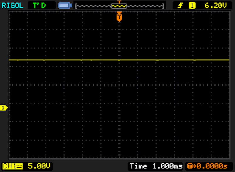
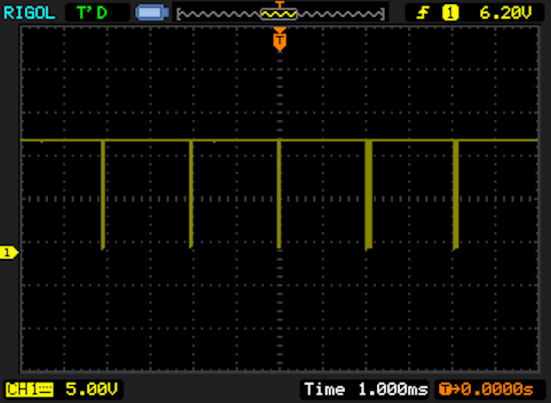
    While a meter is great for reading constant voltages (see first image below) they fall short when a signal is pulsed (see second image below, which is a 12 volt pulsed signal from the switch matrix). What the meter will try to do with this signal is average it and give you a single voltage reading, which is not very helpful. Of course a scope works great on pulsed signals, but is much more expensive, and complicated.

    Specific to pinball, both the lamp and switch matrices are pulsed, plus circuits on the cpu, display and sound boards. While you can infer readings from the switch matrix, for example, using a meter it is much easier to just use a logic probe.

    12-volt-signal.gif12-volt-signal.gif

    Switch-Matrix-Pulse.gifSwitch-Matrix-Pulse.gif

    #2 8 years ago

    Buying a Logic Probe

    In the image below you can see my recommended logic probe, the Elenco LP-560, available at Amazon for $17. You can spend more, but this is really all you need. In addition to all of the standard features (which we'll discuss more in a little bit) it also provides an audible tone in addition to the led's. While this will not benefit you much initially, as you become more proficient there are times when the audible tone provides a better indication of a pulsed circuit than the leds.

    The only function that it does not have is a pulser, which allows you to apply a signal to a circuit. This is a fairly advanced technique and most hobbyists will never have need for it.

    Elenco-LP560.jpgElenco-LP560.jpg

    #3 8 years ago

    Logic Families

    Note: The information in this section has been simplified in order to align with the goal of a beginner level guide. For example, both CMOS and TTL gates have different input and output logic levels, although we will consider them as being the same for our purposes. While not necessary, if you want to fully understand the differences between TTL and CMOS logic levels see the following article at All About Circuits.

    http://www.allaboutcircuits.com/textbook/digital/chpt-3/logic-signal-voltage-levels/

    There are different logic families, or generations, of integrated circuits. Each logic family has different behavior and within each logic family there can be subsets with different characteristics. The only two we need to be concerned with in regards to our discussion are TTL and CMOS.

    TTL chips use a nominal Vcc (Vcc is the fancy term for the supply voltage) of 5 volts and the inputs and outputs are always binary (low, high or pulsed). TTL chips typically, but not always, use a standard naming convention of 54XX or 74XX.

    On the other hand, CMOS chips can use a Vcc ranging from 3 - 15 volts and depending on the chip can have either binary (low, high or pulsed) or analog inputs and outputs. CMOS chips typically, but not always, use a numbering convention of 40XX or 45XX.

    One example of CMOS in a pinball machine is the LM339 voltage comparator used in Williams/Bally switch matrix circuits. We'll discuss this in more detail as we get into the switch matrix examples, but for now the important part is to be able to recognize whether an IC is TTL or CMOS. If in doubt, you can always check the datasheet for any given IC.

    #4 8 years ago

    Logic Families cont.

    Based on the logic family of the chip there are different voltage ranges that are considered to be low or high in a digital circuit. In the case of TTL the low range is 0 - .8 volts and the high range is 2 - 5 volts. So any reading between 0 and .8 volts is considered a logic 0 and any reading between 2 and 5 volts is considered a logic 1.

    The specification for CMOS circuitry in a 5 volt circuit is a low range of 0 - 1.5 and a high range of 3.5 - 5. For a 10 volt Vcc the low range would be 0 - 3 volts and the high range 7 - 10 volts. The high and low voltage ranges scale linearly across the possible supply voltages of 3 -15 volts.

    Thankfully you don't need to remember all that though, since there is a TTL/CMOS switch on the Elenco (and in fact all logic probes except for those that are auto-sensing). Put the switch in the correct position (based on the previous information about CMOS and TTL) and it will correctly read low and high signals for that logic family.

    #5 8 years ago

    Logic Probe Features

    The first thing you will notice is that the logic probe has two wires (red and black) with alligator clips at the end. This is where the probe gets it's power and they must be connected to ground and supply voltage. If you're testing a 5 volt circuit, the red lead goes to 5 volts and the black lead to ground. If you're testing a 12 volt circuit (parts of the switch matrix, for example) the red lead goes on 12 volts and the black lead on ground.

    The pointy thing at the other end from the two wires is the probe. Unlike a meter this single probe is all you need to take your readings.

    There are two switches, TTL/CMOS and MEM/PULSE, that will need to be set properly. If you're analyzing a TTL chip, put the TTL/CMOS switch in TTL and when checking a CMOS chip, put the switch in CMOS. The MEM position on the MEM/PULSE switch will capture a pulse and retain the reading, which is advantageous in some rare situations, but for our purposes here you want it set to PULSE.

    The last, and most important part, of the logic probe are the HI/LO and PULSE led's. The red (HI), green (LO) and yellow (PULSE) led's are used to indicate the state of the measurement point. Note: Some logic probes use different combinations of lights to indicate the status, so just a reminder, I'm specifically talking about the Elenco logic probe here.

    In the first image below you can see the various signals that can be indicated by the led's. In most cases you can narrow these down to three issues: is the line high, is the line low or is the line pulsed. The next image provides another representation, comparing the led's to what you would see on an oscilloscope.

    Elenco-Indicators.gifElenco-Indicators.gif

    tools-logic-probe-hi-lo.pngtools-logic-probe-hi-lo.png

    #7 8 years ago
    Quoted from flipnout1:

    Very nice Terry!

    I figured it was about time you learned how to use a logic probe. I'm sure they didn't give you fancy pieces of equipment like this in the marines.

    #10 8 years ago
    Quoted from Deez:

    What's a good probe to get with a pulser? I could've used that feature a few times and it's about time for me to upgrade.

    I'm not aware of any probe/pulser combos that have an audio beeper. Other than that, the Elenco LP-900 should get the job done. It is also 50MHz instead of 20 if that matters to you. I should also add the LP-900 does not have a ttl/cmos setting. As far as I can tell it uses a fixed logic threshold for both. This generally should not be an issue, but it's worth mentioning.

    The other choices would be Tenma or B&K Precision.

    #11 8 years ago

    Switch Matrix Example

    Now let's look at a real world example (Williams WPC in this case, but the theory is the same on other games) to see how the logic probe works when testing the switch matrix. Note: It is beyond the scope of this article to cover how the switch matrix works. See the following link for more information on the switch matrix.

    https://web.archive.org/web/20190427050931/http://pinballrehab.com/1-articles/solid-state-repair/repair-guides/146-switch-matrix-theory-and-troubleshooting

    https://homepinballrepair.com/pinball-switch-lamp-matrix-troubleshooting/

    The first image below provides a generic WPC switch matrix circuit and we'll walk through what each test point should look like, starting with the column, or send, signals.

    The ULN2803 is a TTL chip that uses 5 volt logic on the input (point B) and controls a 12 volt signal on the output (point A). So the logic probe should be set to TTL and the red lead connected to 5 volts when testing inputs and 12 volts when testing outputs.

    Tip: If you look at the second image below you will see three red circles with pull-up resistors and a supply voltage within them. If the pull-up resistor is connected to a 5 volt supply you know you are working on a 5 volt circuit and if it's connected to a 12 volt source you know you're working on a 12 volt circuit.

    With our logic probe connected to 5 volts and the probe on point B we will get a green light and the yellow light will be pulsing. This indicates a low signal with high pulses. This signal is a constant timing pulse and will not change based on the status of the switch.

    The circle shown at point A tells us that the output signal from the ULNL2803 is inverted. So a high input provides a low output, and a low input provides a high output. Therefore, with our logic probe connected to 12 volts and the probe on point A we will get a red light and the yellow light will be pulsing. This indicates a high signal with low pulses.

    Note: Thanks to zaza for the corrected switch matrix diagrams (these are incorrect in the WPC manual and show an additional connection on the 10K resistor that does not exist).

    Switch-Matrix-Circuit.pngSwitch-Matrix-Circuit.png

    Pull-Up-Resistors.pngPull-Up-Resistors.png

    #12 8 years ago

    Switch Matrix Example cont.

    The row side gets slightly more complex and the readings will change based on the status of the switch. The first part of the circuit we are concerned with is the LM339. It is a CMOS chip that takes a 12 volt signal on the + input (point C) and provides 5 volt logic on the output (point D). So the logic probe should be set to CMOS and the red lead connected to 12 volts when testing inputs and 5 volts when testing outputs.

    With our logic probe connected to 12 volts and the probe on point C we will get a red light with the switch open, which indicates a high reading. With the switch closed we will get a red light and the yellow light will be pulsing. This indicates a high signal with low pulses.

    With our logic probe connected to 5 volts and the probe on point D we will get a red light with the switch open, which indicates a high reading. With the switch closed we will get a red light and the yellow light will be pulsing. This indicates a high signal with low pulses.

    The 74LS240 is a TTL chip and since there is a circle on the output we know that the signal is inverted. So with our logic probe set to TTL, connected to 5 volts and the probe on test point E we will get a green light with the switch open and a green light with the yellow light pulsing with the switch closed. The former indicates a low reading and the latter a low reading with high pulses.

    The image below provides a graphical representation of the logic probe led status for each test point.

    I've really tried hard to keep this at a beginner level while still providing the necessary information and would appreciate any feedback on stuff that needs clarification or is confusing.

    Switch-Matrix-Readings.pngSwitch-Matrix-Readings.png

    #18 8 years ago
    Quoted from not4tilts:

    How does the rate of the blink on the Pulse LED relate to the actual frequency. In the one diagram it says "the rate of which indicates the frequency of pulses". It couldn't be a one for one relationship or you wouldn't see it blinking (in the case of the switch matrix for example)?

    The signal is manipulated before it goes to the led, for example there is a pulse-stretching circuit so fast pulses can be seen. This is why the audio can often provide more information once you get a good ear for it. At a certain point though, it will just look like the light is on solid. I should probably clarify my comment on the drawing since it is a little misleading.

    #19 8 years ago

    Pro Tip

    I often hear people comment they are concerned about sticking a probe or lead into the backbox while the game is on. Here's a couple of products that most professional technicians carry that will help make your life easier, and safer. In both cases you can setup all of your test points with the game off, and then turn it on to take your readings.

    I should clarify by safer that I meant for the game, as in not shorting a couple of pins/components together. As long as you keep your fingers away from AC and the DMD high voltage section you've got nothing to worry about.

    The first is a minigrabber test clip, which has a small J shaped, spring loaded clip for attaching onto resistor, capacitor and transistor leads (see image below--the bottom test clips are the minigrabber type). Due to their design they have little chance of shorting to another component once installed. Buy ones that are long enough you can place the other end on the playfield glass.

    The next item is a DIP clip for testing IC's (see image below). The clip is placed over the IC and provides extended test points where you can use a minigrabber or your test probe to take readings. They come in a variety of sizes, but if you don't want to buy a full selection, you can use a 14 pin test clip which will fit on IC's with more pins, although not all pins will be available for testing at one time.

    In some cases you can also use a larger DIP clip on a smaller IC if there is no physical obstruction on the board (since the clip will extend beyond the IC).

    Ed at Great Plains Electronics sells the 3M product at a great price ($18 for a 14 pin).

    https://www.greatplainselectronics.com/products.asp?cat=6

    Test-Clips.jpgTest-Clips.jpg

    DIP-Clip-and-J-Clips.jpgDIP-Clip-and-J-Clips.jpg

    #22 8 years ago
    Quoted from zaza:

    I can edit and upload the 3 pictures in this post and remove them here afterwards when you have put them in place. Idea ?

    That would be great zaza. Thanks for catching that.

    #23 8 years ago
    Quoted from G-P-E:

    DIP Clips make it very easy to test DIP style IC's so I started selling them awhile back. The ones I have are the 3M clips. Nice but a bit higher priced than the blue Pamona's:

    I would suggest people buy from Ed and support our community. The 3M is a better product than the Pomona so you're getting your money's worth, plus that is a great price that Ed is offering.

    I added the Great Plains Electronics link to my post above (sorry Ed I didn't realize you carried them).

    #24 8 years ago

    Thanks zaza, I updated my posts with the new images.

    3 weeks later
    #25 8 years ago

    I'm still seeing a lot of questions on logic probes, so a little bump is in order. This is really a must have tool if you're going to do board repair.

    #30 8 years ago
    Quoted from smailskid:

    What reading on the the logic probe should we expect at pin 17? How do we know what pin is the input for pin 17 and what reading would we expect there?

    In regards to pin 17 you want the game to be in a situation where that lamp should be going on and off (attract mode is typically a good choice). Or you can go into lamp test and turn the lamp on and off while monitoring pin 17.

    Over time you'll learn what state a line should be in when it is enabled or disabled, but when you're starting just look for the state to change when you change the input.

    There is not a one-to-one relationship between pins on a PIA. It taks in 8 bit data and converts that to individual outputs. If you were missing a data/address line you would see multiple problems.

    #31 8 years ago
    Quoted from laanguiano:

    I'm a little confused on how you are supposed to know what the probe should be showing, and how to figure that out. I know you said, "In the case of TTL the low range is 0 - .8 volts and the high range is 2 - 5 volts." but I cannot relate how that coincides with the schematic.

    I think you're asking how do you know if the test point should be low or high?

    If you don't have extensive electronics experience (to the point where you can just read a circuit and figure out what is going on) there are a couple of choices. Probably the easiest is to compare the circuit in question to a known working circuit. The next is as I described above, is to change the input and see if the output changes.

    For example if you are working on a solenoid problem. Put your logic probe on the test point and then activate the solenoid. If the reading was initially low it should go high and if the reading was initially high it should go low.

    If you want to get a little deeper into it then the following series of articles should help with a basic understanding of electronics.

    https://web.archive.org/web/20190426142717/http://www.pinballrehab.com/1-articles/solid-state-repair/tutorials/147-solid-state-pinball-tutorials

    Also remember that IC datasheets are your friend. The datasheet for any IC will typically provide a truth table that will tell you what the output should be based on the possible inputs.

    If I missed the point of your question let me know.

    2 weeks later
    #34 8 years ago
    Quoted from UvulaBob:

    Sometimes, when I poke at a chip with my probe, a pin might be neither high nor low. It's just... dead. I can kind of understand how an input pin might read dead (based on the state of the circuit leading to that pin) but why would an output pin on something like a 7408 or 7402 read anything but low at the very least?

    Can you provide a specific example? Also keep in mind that sometimes not every gate on an IC is used.

    #36 8 years ago

    I'm no system 6 expert, but from what I see in the 6802 datasheet I would expect to see a valid logic level on pin 4 (CB2) and thereby pin 6. Do any of the switches work?

    Quoted from UvulaBob:

    I guess what I'm wondering is this. Of all the states a logic probe is presented as possibly being in, "no lights or sound at all" isn't one of them. Under what circumstances is would a logic probe legitimately show no activity whatsoever?

    No lights and no sound would indicate a bad logic level or no input (see the first image under logic probe features). There are some rare instances where you will see an input or output that was left floating (by design) and you could get wonky readings. You seldom see this though since it is not generally recommended to design a circuit this way.

    Maybe someone with more system 6 experience can jump in here and be more specific in regards to your situation.

    2 months later
    #40 8 years ago

    Thanks for sharing that wxforecaster. While the theory shit is great a real-life example is worth a 1,000 words. I mentioned this earlier, but this is why learning how to "read" the audio will sometimes give you more information than the led's.

    Good troubleshooting, btw.

    Don't have any soldering stories do you???

    1 year later
    #45 7 years ago
    Quoted from Topher5000:

    He asked if it was audible & you said that it's not necessary.

    It is a nice feature if you work with a logic probe a lot and get a good ear for the tones. In some circuits you can hear problems that you might not catch using the led's. In my case though I usually just move on to an oscilloscope on those types of circuits. So bottom line it can be nice if you use a logic probe a lot and have a good ear, but is not really necessary for most people.

    The Elenco 560 I recommended at the beginning of the article has audible tones.

    1 month later
    #47 7 years ago

    If you're checking the row or column at the connector that goes to the playfield that is CMOS. So connect the power to 12 volts and ground and set the switch to CMOS.

    The first clue is the signal is 12 volts at that point and TTL chips are limited to an output of 5V. If you want to confirm just google the datasheet for the associated IC. If you're working on a WPC game that would be a ULN2803 for the send and LM339 for the receive. Both are CMOS.

    #49 7 years ago
    Quoted from terryb:

    In the case of TTL the low range is 0 - .8 volts and the high range is 2 - 5 volts.

    So yes, you can derive the answer from those numbers. The high range is a minimum of 2 volts and the low range is a maximum of .8 volts so that is a TTL chip. The chip inputs/outputs would be tested with the logic probe set to TTL and power from 5 volts (the chips Vcc). Normally the datasheet will state whether a chip is TTL or CMOS, but that one does not appear to have that information.

    Quoted from pedroborges:

    The plug j205, j207, j209 are tested with the logic probe in ttl ?

    At J206, 207, 208 and 209 you would set the logic probe on CMOS and get power from 12 volts.

    Have a look at the image in post 12. The 74240 chip is TTL with a Vcc of 5 volts, but the chip that reads the signal at the connector is an LM339 which is CMOS and the Vcc is 12 volts. Different chips on the send circuitry, but the same issue applies. It is not uncommon for TTL and CMOS chips to be intermixed in the same circuit.

    #52 7 years ago
    Quoted from pedroborges:

    But in j206 one should not choose TTL since the uln2803 connects in plug j206 ?

    You are correct ULN2803 is TTL and red connector on 12V.

    #53 7 years ago
    Quoted from pedroborges:

    TTL integrators always use 5 volt supply voltages, do the cmos always use 12v supply voltages?

    CMOS chips can use a supply voltage from 5V to 18V.

    4 months later
    #55 6 years ago
    Quoted from pedroborges:

    The plug j206 and j207 is tested with the ttl logic probe connected at 12v right?
    The plug j208 and j209 is tested with the cmos logic probe connected at 12v right?

    Correct.

    5 months later
    #58 6 years ago
    Quoted from metalkatt:

    Great read-through!! Question - Can you use a logic probe to test sound board IC's? Have MC3403 IC that I'm curious about on my Data East sound board. It acts as a amplifier chip. My music part is very faint, almost non-existent but my sound effects are fine...separate IC. Thank you again for your info!

    Sorry for the delay in responding, been out of circulation for a while. Yes you can use a logic probe to test IC's on the sound board. If the chip is marginal you won't learn much unless you've worked on enough of them to tell by the tone. Most failures though will definitely be obvious.

    #60 6 years ago
    Quoted from Kawydud:

    This was my first time using the logic probe, it was like a whole new world opening up diagnosing transistor failures.

    Glad to hear it. It really is a valuable tool to have in your arsenal.

    4 weeks later
    #63 6 years ago
    Quoted from YeOldPinPlayer:

    I don't think 36v would smoke a probe rated for 15v max immediately, make it explode, or melt it.
    If I did that I would at least test it by comparing readings to a known good probe before trusting it again. Obviously the higher the overvoltage the greater the opportunity for damage.

    Well said. Since you're typically working on the logic part of the circuit you really shouldn't have an issue with hitting a high voltage.

    #69 6 years ago

    On the LM339 you would test the inputs with your probe connected to 12V and the outputs with it connected to 5V. In zaza's drawing the yellow are 12V and the red 5V.

    More info here:

    https://pinside.com/pinball/forum/topic/terrybs-guide-to-logic-probes#post-2514887

    #71 6 years ago
    Quoted from pedroborges:

    the probe must be connected to the supply voltage of the integrated ?

    The probe should be connected to the voltage range that you are reading rather than the chip's supply voltage. So if you're taking a reading with a high of 12V connect the probe to 12V and for a high reading of 5V connect the probe to 5V. This is how the probe determines the logic thresholds for a hi and lo.

    I'm not sure what input + and input - mean. To me the inputs are the 12V side and the outputs the 5V side.

    #74 6 years ago
    Quoted from pedroborges:

    I can test the inputs and outputs of the all integrated ones with the logic probe powered at 5 volts ?

    No. In zaza's drawing above you should connect the logic probe to 12v for the yellow and 5v for the red.

    #76 6 years ago

    The LM339 has 12v inputs and 5v outputs and you have to match the probe to that not the Vcc for the chip (5v).

    #79 6 years ago

    switchmatrix (resized).pngswitchmatrix (resized).png

    #81 6 years ago
    Quoted from pedroborges:

    the inputs and outputs of the lm339 in what state should they be while testing with the logic probe?

    That varies depending on the state of the switch. See this post.

    https://pinside.com/pinball/forum/topic/terrybs-guide-to-logic-probes#post-2514887

    Quoted from pedroborges:

    the inputs and outputs of the uln2803 in what state should they be while testing with the logic probe?

    The output will be high with low pulses and the input low with high pulses.

    Quoted from pedroborges:

    I think the output to the schematic is +18 volt, but I do not know what the input voltage is

    The input is 5v.

    Posts 11 and 12 in this thread walk you through testing the row and column, including what voltage to connect the logic probe to.

    #83 6 years ago
    Quoted from pedroborges:

    the integrated 74hc237 is a CMOS chip right?

    to test the inputs of the integrated 74hc237n I put the logic probe in CMOS and feed the logic probe to + 5V

    to test the outputs of the integrated 74hc237n I put the logic probe in CMOS and feed at +5 volt

    Was this how I should test the logic probe?

    That is correct.

    #85 6 years ago
    Quoted from pedroborges:

    Thanks, The 74hc237n connects to the inputs of the uln2803.
    to test the inputs of the uln2803 I put the logic probe into ttl and feed the logic probe to 5 volts.
    To test the outputs of the uln2803 I put the logic probe in ttl and feed the logic probe 12 volts.

    Was this how you had to test with the logic probe?

    Correct.

    Quoted from pedroborges:

    Do you know what it is that has to give in the logic probe for the inputs and outputs of the lm339 and for the inputs and outputs of the 74hc237n ?

    Not sure what you're asking.

    #89 6 years ago

    I prefer the Elenco LP-560, which is the one I cover in this guide. It has audio which the 900 does not. The 900 also does not have a cmos/ttl setting. While this might seem like an advantage, in that you avoid the hassle of figuring out which setting to use, the probe uses a hybrid threshold for cmos and ttl and therefore will not always be 100% accurate. It does have a pulser though, but honestly I seldom use the pulser and if I do need a pulse I can always pull it off the board somewhere. I'm not familiar with the BK product.

    #91 6 years ago
    Quoted from pedroborges:

    thanks , Could the logic probe elenco lp-560 be connected to +18 volts?

    Yes.

    Quoted from pedroborges:

    I saw this logic probe on amazon.com.

    but since I am from portugal, may I have to pay customs fees ?

    No idea.

    #94 6 years ago
    Quoted from pedroborges:

    on uln2803 I think that in order to test the inputs I had to connect the logic probe at 5 volts and then the logic probe in ttl, to test the outputs of the logic probe at 18 volts and put the logic probe into ttl.

    Technically the output should be set to CMOS, although either would work. The rest is correct.

    Quoted from pedroborges:

    I think that in order to test the output of the lm339, I turn on the logic probe at +5 volts, and I put the logic probe in cmos.

    Correct. The outputs are both TTL and CMOS compatible so you could actually use either one.

    Quoted from pedroborges:

    to test the entries of lm339 is that i do not know

    Haven't worked on a lamp matrix in a while, I think 18V and CMOS. If you get weird readings then try 5V and CMOS.

    #96 6 years ago

    ULN2803 is a CMOS chip. The inputs are TTL compatible but the datasheet does not say the outputs are TTL compatible so I would go with CMOS.

    http://www.ti.com/lit/ds/symlink/uln2803a.pdf

    #100 6 years ago

    If you momentarily shorted 5v to ground you could cause a reset, but it is unlikely you did more damage. There are other CMOS chips though where it's possible to short 12v or 18v to the logic circuit and that will likely blow something.

    My hands aren't as steady as they used to be so I typically use a DIP clip and micrograbber. Normally you're just testing a couple of points so you can set everything up with the power off and then just get your readings from the other end of the micrograbber.

    https://pinside.com/pinball/forum/topic/terrybs-guide-to-logic-probes#post-2517164

    #101 6 years ago
    Quoted from pedroborges:

    but if cpu board tested the outputs of the uln2803 in ttl, the power drive board should not be equal to the test ?

    Either one will work. Sometimes it's a gray area when you get a CMOS chip that is TTL compatible. My earlier thread on the ULN2803 on the cpu should probably say CMOS rather than TTL, but again either one will work in this case.

    #104 6 years ago

    The wiki is kind of confusing because of the heading, but it does say the 74HC237N is CMOS.

    "74HCXX High Speed CMOS Type"

    Here's the datasheet, which states it is CMOS.

    http://html.alldatasheet.com/html-pdf/15567/PHILIPS/74HC237N/499/2/74HC237N.html

    It is TTL compatible (as are a lot of CMOS chips) and that, I think, is what's causing the confusion. So while it is a CMOS chip it can be tested with either TTL or CMOS on the logic probe. That is why the answer is not always black and white, but kind of gray.

    3 months later
    #109 5 years ago

    Pins are numbered counter-clockwise from the dot or notch on the chip. So pin 1 in your example is on the bottom left.

    #113 5 years ago
    Quoted from Atari_Daze:

    Since it is for flasher, would I expect a pulse signal?

    Yes. Best to always compare to a similar circuit (another flasher in this case).

    You're currently viewing posts by Pinsider terryb.
    Click here to go back to viewing the entire thread.

    Reply

    Wanna join the discussion? Please sign in to reply to this topic.

    Hey there! Welcome to Pinside!

    Donate to Pinside

    Great to see you're enjoying Pinside! Did you know Pinside is able to run without any 3rd-party banners or ads, thanks to the support from our visitors? Please consider a donation to Pinside and get anext to your username to show for it! Or better yet, subscribe to Pinside+!


    This page was printed from https://pinside.com/pinball/forum/topic/terrybs-guide-to-logic-probes?tu=terryb and we tried optimising it for printing. Some page elements may have been deliberately hidden.

    Scan the QR code on the left to jump to the URL this document was printed from.