
Hey experts, I have here a System 1 power supply that I'd like to rebuild just for fun. The previous owner had replaced it with an aftermarket in an attempt to get the machine working. The machine is now working great with the new power supply but I wanted to fiddle with this one to see if I could get it going again.
Before I looked anything up online I hastily reassembled it and plugged it in just to see where it was at. The previous owner had it disassembled in pieces when I got it. I didn't realize that I was missing the insulators, so it went poof! Oops ![]()
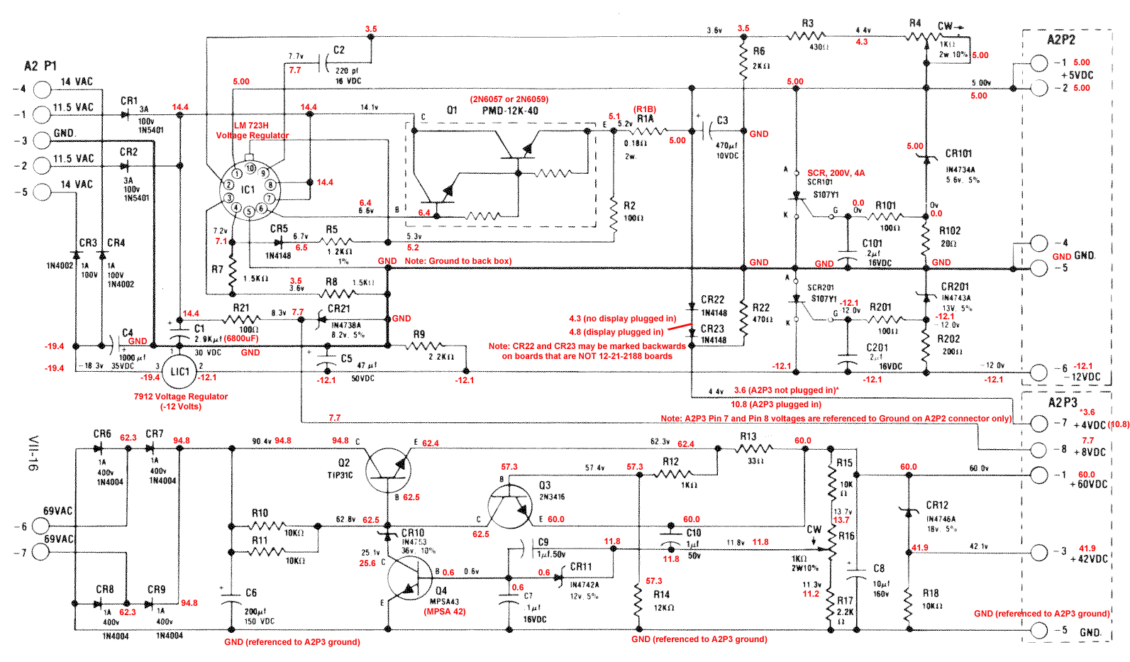
So after actually reading a couple guides on these I replaced Q1, Q2, and LIC1 for obvious starters (with insulators!), CR3 and CR4 because they burned, and all the electrolytic caps. Now my low voltages (5, -12, 8, 4) are 5.58V, -11.92V, 8.72V, and 4.16V so the low voltage side seems pretty good. Are the 8 and 4 reference voltages close enough? Couldn't find how accurate those should be. I realize I can trim the 5V.
Now for the high voltage side, I was getting like 90V I think where 60V should be. I noticed R14 and R17 were pretty hot and looked cooked so those should be replaced obviously. For the cost of shipping it was cheap enough to simply order EVERY component for the high voltage side. I started with the bridge rectifier diodes but thought maybe I should stop to learn something here. So my question-
Is there a way to go about this systematically to find out where the issue lies or will I just cause more damage replacing some components and leaving others that are possibly bad?
My thought as an amateur was to replace Q3, Q4, and the burned resistors and see where I was at, but I'm afraid if something else is goofed I'll just smoke the new transistors.
Obviously I have a rudimentary knowledge of electronics especially passive components and am a skilled solderer of mostly analog stuff but when it comes to theory of transistor pairs and whatnot I start to get lost.
Thanks!
 Omaha, NE

