 Woodridge, IL
All:
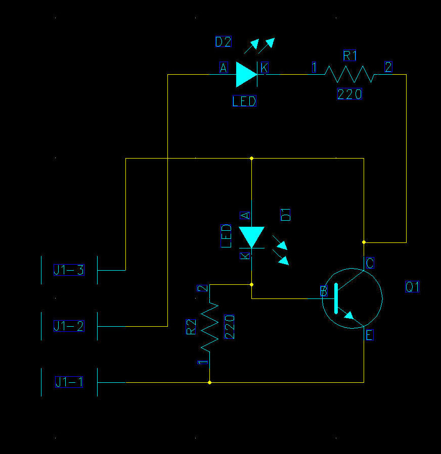
Tried this on a different part of Pinside, hoping someone here may have the answer. A long time ago I purchased a "Third magnet Kit" at expo. In the box was a couple Optos. The pix are below. The problem is I am not positive which is the Kathode and Anode on the Transmitter, and which is the Collector and Emitter on the Receiving Opto. The interesting part is they are marked, but don't appear to be used. The wires (which are not labeled) are connected to other solder points on the board.
If I can't get this answered, here is my next question. Can I do any harm to these things if I put the wires on the wrong way on either side? I really don't want to assume though. There are a lot of changes to make this 3rd magnet work and would like to get this right so I am not chasing shadows. I guess another option would be to buy a new pair of optos.
Any info/ideas would be greatly appreciated...
Dave
 Screen Shot 2020-06-07 at 12.28.08 PM (resized).pngScreen Shot 2020-06-07 at 12.28.21 PM (resized).png
