(Topic ID: 286591)

Street Fighter II Pinball + Arcade (Homebrew Project)

By Time

3 years ago


Topic Heartbeat

Topic Stats

  • 91 posts
  • 26 Pinsiders participating
  • Latest reply 45 hours ago by mtn-
  • Topic is favorited by 24 Pinsiders

You

Linked Games

Topic Gallery

View topic image gallery

20240416_231323-ezgif.com-optimize.gif
20240416_215603 (resized).jpg
20240416_224604 (resized).jpg
20240416_224044 (resized).jpg
20240416_214527 (resized).jpg
20240416_202026 (resized).jpg
20240416_202422 (resized).jpg
20240415_224339 (resized).jpg
20240415_225015 (resized).jpg
20240415_225004 (resized).jpg
20240127_203338 (resized).jpg
20240131_005718 (resized).jpg
20240130_000805 (resized).jpg
20240131_005444 (resized).jpg
20240127_220513 (resized).jpg
20240127_204625 (resized).jpg

You're currently viewing posts by Pinsider Time.
Click here to go back to viewing the entire thread.

#1 3 years ago

Is it Homebrew? I don't know. I'm building it at home and it didn't come from the factory this way so... Yes?

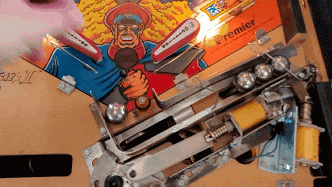
So I got this Street Fighter II Championship Edition Pinball Machine. It's amazing, despite what some salty threads here say about it, love this game. Never got into the arcade game but it was huge. Like one of the most profitable arcade titles ever huge. This pin would never exist without the arcade obviously and its (IMO) pretty faithful to the arcade. Most of my friends remember the arcade, almost zero remembered the pinball. However depside that, its a visitor favorite at my house because its easy to start, easy to learn, and difficult to master. So Pinball vs Arcade?

Why Not Both?Why Not Both?

*** Introducing ***

Street Fighter II Pinball AND... Arcade cabinet! All in One

SF2 is a meaningful pin for me. My parents bought this title back in 1994 and it introduced me to Pinball. We sold that cabinet off during a move. Since starting my own pinball collection, I had been looking to buy this title back. Been collecting parts for this build for months and I'm ready to start. Follow a long with me! This is totally a side project and I have a lot of those (side projects) happening. So... I'm not working on this every day but I hope to post updates every month or so.

Project Goal Date: Dec 31st 2021 MISSED (opps?)
Project Budget: Under 5k Under 8k (all in)

My Project Rules

  1. Reversibility: I don't want to do anything that's not really reversible. So no new holes through the cabinet. When modifying parts, it needs to be easily obtainable and I'll only modify a used replacement. I will keep all of the original parts.
  2. Quality: I want the fit and finish to appear factory when possible. I have to rely on others for parts of this, so I may be unable to control quality on every piece.
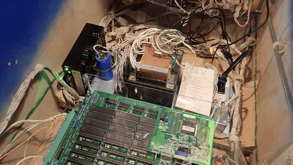
  3. Genuine Arcade Hardware: Emulation is too easy. Its a real deal pinball machine, the arcade should be real deal arcade hardware. Though I must make an exception for the LCD. Putting a CRT in this would involve cutting the backbox and that breaks rule 1. So that's Genuine game roms, JAMMA cables, real arcade buttons, ext...
  4. Everything Works: At the end of the day everything needs to still work. It needs to be actually playable as an arcade (2 player), and as a pinball machine.

So let the project begin

  • Step 1 - Acquire Pinball (done)
  • Step 2 - Acquire Arcade Hardware (done)
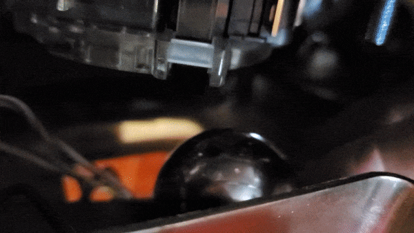
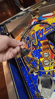
  • Step 3 - Begin Fabrication (started)

Photos and progress below ↓↓↓

#2 3 years ago

Here's the pin Im starting with:
Street Fighter IIStreet Fighter II

It's pretty clean example but I'm planning on stripping everything down and doing a full shop on this as I go. I'm not really setup to do paint touch up. Maybe I'll contract that out as I get further along.

SF2 w/ Ayce Gogi dinnerSF2 w/ Ayce Gogi dinner
20201130_175156 (resized).jpg20201130_175156 (resized).jpg
20201130_175355 (resized).jpg20201130_175355 (resized).jpg
20201130_175233 (resized).jpg20201130_175233 (resized).jpg
20201130_175133 (resized).jpg20201130_175133 (resized).jpg
20201130_175429 (resized).jpg20201130_175429 (resized).jpg
20201130_175403 (resized).jpg20201130_175403 (resized).jpg

#4 3 years ago

Step 2:

Original Capcom Street Fighter II ~Championship Edition~ cps2 boards and roms. Whooo Hoo! No emulation here. Now... will I risk it and power the boards from the pin's power supply? That would be pretty fetch if I did.

Capcom CPS 2 BoardCapcom CPS 2 Board

Original hardware means JAMMA connections. Since I must use an LCD, I'm going to take some liberties and use a supergun to connect everything. I feel like thats still keeping with the arcade spirt. Though obviously I'm breaking the "factory" feel doing this. I just don't know enough about arcade hardware to attempt this without this shortcut.

Arcade hardwareArcade hardware

I've got an OSC to upscale the native RGB. Realistically I just can't get an LCD that's native. After some research, I found arcades that replace their CRTs with LCDs used this with good results. Since I must use LCD, this seemed necessary to get the CRT look.

19" 4:3 Arcade LCD19" 4:3 Arcade LCD

The LCD monitor is 4:3 aspect arcade CRT replacement screen. It's supposedly designed for this application. Fingers crossed it looks good. The best part though is that it fits the backbox nearly perfect. I plan on having the screen where you see the blue tape. That allows me to preserve the existing translite artwork.

Added over 3 years ago:

*Correction - It's CPS 1 Arcade Hardware, not 2

#5 3 years ago

Here's an idea of what the translite could look like by keeping the original artwork.

LCD in Backbox MockupLCD in Backbox Mockup

#6 3 years ago

While I'm at this, I have some mods in mind for the game. One is going to be a little SF2 arcade cabinet. I've mocked up the size in paper around a little 4:3 LCD TV I had from another project. The tiny LCD screen has lower resolution as the native arcade hardware. Hoping it still looks pretty good in there. This screen and the large one in the backbox will both show the same output.

NTSC/PAL (Television) TFT Display - 1.5 160x 240NTSC/PAL (Television) TFT Display - 1.5 160x 240

Paper mock up of SF2 cabinetPaper mock up of SF2 cabinet

Not sure how I'm going to make this mini arcade cabinet yet. I'll probably design the first version and send it off to be 3D printed. Then I'll likely work with a freelance 3D artist to make it property. I know almost nothing about 3D Printing. It may go here above the loop shot but I initially designed this to fit over the Balrog hole. That location looks cooler imo but it involves removing a lot of game plastics.

#7 3 years ago

One part I've already had cut is the button panel for the arcade controls. This is version 2, I've got another one on it's way. Its aluminum and the same thickness as the glass. The idea is that it sits inside the glass channel and below the existing lockbar. This way nothing with the cabinet needs to be modified. I will need to buy a custom piece of glass. Plastic H channel will sit between the glass and this panel to keep everything sealed and tight (hopefully).

I will design a decal to match the control look of the SF2 arcade. This panel is roughly 20% narrower than the arcade. So its tight, but all of the full size buttons and joystick do still fit. I do have to move the Player 1, Player 2 start buttons but I have an idea for that.

Version 2 of the button panelVersion 2 of the button panel

There are some components below this that need to move though. More on that later.

#8 3 years ago

The plan is to have the coin door sever both games. One slot will be for Pinball, the other for Arcade. Easy enough. I'll design a decal to indicate which does what.

The arcade hardware requires buttons to select 1 or 2 player. They don't fit up top so they may go on the bill accepter slot. Though I kind of don't like that it involves drilling holes. Though, arguably, still reversible using the bill slot plate.

20210125_183949 (resized).jpg20210125_183949 (resized).jpg

Another, some what wackier, choice could be replacing the flipper buttons with the player select buttons. I think this is possible but I haven't tested it it. 1 player would be on one side, 2 player would be on the other. Its not like you'd ever play both games at the same time, but still I think it would technically be possible even doubling up the use of these buttons.

20210125_183851 (resized).jpg20210125_183851 (resized).jpg

#9 3 years ago

One of the biggest problems with the button panel is fitting the joy sticks and buttons underneath it.

Keeping with real arcade hardware meant fitment was going to be a challenge. In the US, SF2 would have originally come with Suzo-Happ buttons. But they're just way too long to fit. As I understand it, the Japanese cabinets used Crown style buttons. And luckily the Samducksa screw in versions are just barely short enough. However the joysticks are still a problem.

  • The buttons are 30mm Crown/Samducksa SDB-201
  • The Joysticks are Sanwa JLF-TP-8YT Joystick

The biggest issue is the coil that sends drained balls up the trough. Its sitting directly underneath the right joy stick. I looked at every which way to do this and it just needs to move. My plan is to cut the metal bracket holding the coil. Keeping the same angle I'll move the coil back 3 inches. Then I need to make a 3" longer plunger rod link (the brown/red part below) to reconnect everything.

Original ball troughOriginal ball trough

I got a rusty used part off eBay to cut up. A friend welded the piece for me. I do need to make some more modifications still. It seems the version I got is slightly different than the original one in my game. Once I get this piece mechanically working I'll sandblast and re-plate. I'm hoping no other parts under the apron need to be modified.

Replacement / Modified trough installedReplacement / Modified trough installed
Notice how the replacement has extra cross brace where the original had only one. I need to cut off the second brace as it blocks a switchNotice how the replacement has extra cross brace where the original had only one. I need to cut off the second brace as it blocks a switch

#10 3 years ago

Tonight's project was figuring out this 3" longer coil rod link. I popped the pin out of the original. Scanned the original link and designed a new piece in cad. Going to send this out for cutting tonight and should have it in a few days. I made a crude cardboard one to sorta test it but it was useless. Really wish I had a laser cutter or cnc on hand. But... that's overbudget for this project.

Drawling new coil rod link based on the originalDrawling new coil rod link based on the original

The video shows close ups of the modified bracket, the problem I have with the extra brace, and roughly how the longer coil rod link will work. I'll extend and re-route the coil wiring if this approach works.

Needed to buy a new tool to pop that roll pin. Never done this before. I'm the proud owner of a $10 roll pin punch set now. Whoop Whoop

#14 3 years ago
Quoted from latenite04:

Once you have controls mounted on the aluminum panel how will it slide past the front of the cabinet to get into place?

Quoted from Mbecker:

Concerned about this control panel though - it sounds like it could be a bit annoying when you have to remove the glass for maintenance or stuck balls, etc?

You're both right. There was one crucial part I didn't mention about the next version of that panel. Version 1 & 2 were just about button placement and height so it doesn't interfere with playing pinball. Version 3 has a frame that slides in place and the button panel is attached to the frame via a hinge. That way the buttons can lift up and the whole frame & panel can slide out. I'm going to wire it so there's a single Molex disconnect to remove for the buttons wiring.

My buddy is in the process of welding a lengthwise aluminum hinge to the V3 panel. When I get it back I can demonstrate how the lockbar & panel frame work together. I suspect there may be a future V4 and V5 as this is a critical part that needs to work well. I didn't want to mess with the lockbar itself. It appeared to be a somewhat rare part when I started researching this. Also since my hands rest on that while playing, I didn't want to have to worry about perfect finishing on the piece. With the current approach I can cover the whole button panel & frame with a vinyl decal, much like the original arcade cabinet.

Fortunately, in the 7-8 months I've had this game, I've never had to open the glass for a stuck ball. The pin hasn't been shopped yet but its been pretty damn reliable outside of the existing issues it arrived with.

Version 3 of the button panel w/ FrameVersion 3 of the button panel w/ Frame

An aluminum hinge will go between the frame and button panelAn aluminum hinge will go between the frame and button panel

The hinge idea came from how some arcade button panels swing up or down for service. I'm not actually sure if street fighter arcade does that though. I've just seen it somewhere.

#16 3 years ago
Quoted from Isochronic_Frost:

Looks like the TRON mini-arcade mod that was super popular. Look that up! It’s exactly what you want but SFII instead of TRON.

Yeah I had that mod when I owned a Tron. Very similar. Except that used an even smaller OLED screen with a very small amount of internal memory and cpu to draw the animations. It wasn't interactive at all, just on a programed loop. That was designed to look like the Tron cabinet. Cool mod, but ideally I'd make something closer to the street fighter arcade cabinet. The screen I have is an TFT TV. Picture quality will be less but at least I can feed a composite signal to it directly.

Using the screen I have, mine will end up being about twice the size of the Tron mod

#19 3 years ago

Here is how the button panel will work. When the buttons and joy sticks are installed, they can flip upward. The whole unit can then slide out from the glass channel. The existing lock bar keeps everything secured and in place.

I am looking for a plastic h-shaped channel molding to go between the aluminum button panel and the new shorter pinball glass.

20210129_130347 (resized).jpg20210129_130347 (resized).jpg
#20 3 years ago

Test mounted the joysticks and buttons.

Arcade controls - Test FitArcade controls - Test Fit

I knew I had to mount one joystick sideways. I may still cut another version of this panel with proper screw hole locations. I don't yet know exactly what hardware I'll use to attach the joysticks to the panel. I do know they won't be phillips head screws like I used here for testing. Maybe some tiny stainless carriage bolts?

Arcade controls - Test FitArcade controls - Test Fit

Unfortunately the clearance just barely doesn't work and the metal drain guide needs to be modified. I'll have to cut a small notch from the top of the metal rail. Which means I need a replacement part before I can proceed. Oddly, I can't find this part number anywhere, but I did just order one on ebay for what seems to be way more than it should have been I hope this part isn't rare.

Underside of the panelUnderside of the panel
Metal ball drain guideMetal ball drain guide

Clearance is going to be tight but it looks like I'll still have enough room for the balls to travel through the trough.

Clearance testClearance test
Clearance under the panelClearance under the panel

2 weeks later
#23 3 years ago

The replacement ball trough guide arrived. I have modified both the guide and trough pieces. The metal guide required a notch cut to make room for the right joystick. The trough needed to be further cut to allow the trough switch room to move. The piece is otherwise identical to my original.

At some point Gottlieb must have changed the trough switch. The original trough doesn't have a metal brace where this red x is.At some point Gottlieb must have changed the trough switch. The original trough doesn't have a metal brace where this red x is.

Wishing I had just bought the correct ball trough initially. Cutting this out with a hand power tool, I nicked the side by mistake. Now I have a dead spot where the ball could get stuck if rolling slow. It doesn't seem to be a problem in initial testing. But I fear I'm going to be back in here addressing this mistake at some point.

The replacement guide rail was also slightly different. The original had holes further back for the wire gate. I had to drill a 3rd hole to match. Otherwise this piece is identical to the original. Perhaps older Gottlieb trough held fewer balls.

Original sitting on top, replacement is missing a hole for the wire gate.Original sitting on top, replacement is missing a hole for the wire gate.
The original on the right, replacement on left. Marked where a new hole was requiredThe original on the right, replacement on left. Marked where a new hole was required

It doesn't have to be perfect, just need enough room for the joystick. However too low would be a major problem for the trough guideIt doesn't have to be perfect, just need enough room for the joystick. However too low would be a major problem for the trough guide

Using an oscillating cutting tool with carbide blade. Cuts too easy. Very easy to screw up as I learned. Wish it looked better, but I'm never going to get a totally perfect cut doing it like this. Did the best I could using the vise as a straight edge.

cutting the notch for the joy stickcutting the notch for the joy stick
Not my proudest work. But going for function over beauty at this stage of the project.Not my proudest work. But going for function over beauty at this stage of the project.

Next steps - I never ordered that 3" longer coil rod link. There's a minimum order for the cutter. Going to design several slightly different sizes to make up for the minimum. At least then I know one will work. Can't think of anything else I need to order in that material size just this moment. I'm also going to go shopping for the plastic H-channel that will sit between the glass and this button panel.

#24 3 years ago
Quoted from Luckydogg420:

I think from this angle it looks like that really blocks the view of the flippers.

Quoted from Mbecker:

I did have the same thought about blocking view of flippers.

This was a concern for me when I first designed it. I considered a V but that would make the glass kind of dangerous when opening it up. A V-shape also doesn't really give me any more usable room for buttons or joysticks and the hinge design would be wackier. Keeping it straight across was just easier all around.

The panel doesn't go beyond the center ball save post. Its aligned about 3mm below it. If you're short (or stand far back from the game), yeah it does block the center drain post. It hasn't been an issue for me yet and the bottom of flippers are easily seen IMO. The top of the panel cuts into the artwork at the bottom most point about 9mm. I have enough room to cut the same amount off the bottom of the control panel that goes under the lock bar. However trying to avoid that as I think it would make the action buttons too close to the lockbar.

I'll try to post a better view of what it looks like when I get the next round of parts installed.

I've been thinking of designing some kind of spring loaded catch for the new shorter playfield glass. It would be useful so the panel could be removed without the glass falling down at the same time. Not super sure of the best way I could do that yet.

#25 3 years ago

Love SendCutSend - Couldn't do this project without them. They do have minimum orders so sometimes that can get pricey if you don't have a lot of parts to order. Unforuntely I really only need the one piece in this material thickness right now. But still way cheaper than having a CNC myself. Since I have to wait for shipping and turnaround, I ordered 7 versions of this part with 2mm difference between each. One must fit right??

SendCutSent OrderSendCutSent Order

SendCutSent doesn't do MDF unfortunately. So I'm going to have to get the custom backbox light board done elsewhere. Anyone got an online CNC shop they recommend that does MDF?

#26 3 years ago

Got various moldings to test between the panel and the glass. I don't expect it to be water tight, but I do want some protection. Mainly this trim is to make the join look good. I tried rubber molding you'd find on a shower door. It didn't look good. I realize now flexible wasn't the way to go. It would make removing and reinstalling the glass a pain each time. I also tried 3/16" hard plastic H channel. I have it in both black and clear. This is the way to go. Fits the glass perfectly, but the panel is too thick. Ugh

Molding optionsMolding options
Molding testMolding test

Ok, time to order Version 4 of the panel then. This time I'm making it 1/16" thinner. It will be the same thickness as the glass once the piano hinge is welded on. But I'm pretty worried this will be too thin and bend on me. The top of the frame will be 4mm shorter. I'm also ordering this version out of 3mm cold rolled steel. Might be pushing my luck with all of these changes. Welding aluminum was a challenge last time. I don't think it turned out as great as it could be. I need to get more hinge to build V4. What I have extra on hand is aluminum though I'm not ruling out the final finished version made from aluminum yet.

V4 of the arcade frame and panelV4 of the arcade frame and panel

I did play around with having the hinge at the bottom underneath the lockbar instead. This makes it look cleaner. Way safer for liquids leaking in too. However this creates a new problem when trying to install the plastic H channel. Part of the panel has to lift upwards to remove it. Opening from the top with a plastic channel up there would make installing this a nightmare every time. It needs to function well first, so the hinge is staying on top and it will continue to open from the bottom.

Testing hinge at the bottom - It doesn't work with H channel installed on topTesting hinge at the bottom - It doesn't work with H channel installed on top

Trying to give you guys an idea of where the panel sits relative to the flippers. Version 4 - If it works, is 7mm shorter than this one.

Overhead view of the panelOverhead view of the panel
Rough approximation of what I see when standing backRough approximation of what I see when standing back

#28 3 years ago

The longer coil rod links arrived and the ball trough mech is working again. It seems a ball stays in the drained position and only shoots up to join the stack after a new ball is put into play. Never realized that, I definitely need to watch out for this when lifting the playfield.
Ball trough with 3 inch longer coil rodBall trough with 3 inch longer coil rod

The original linkage used a spring to hold the arm in place (see below). My replacement came with e-clip retaining rings. I guess this was a production change along the way. I'm going to order a spring for the replacement part. I think the spring is designed to reduce vertical movement. Currently I have a good deal more vertical play compared to the original piece. Certain times I can get the arm to catch as it moves through metal ball guide.
Spring (newer) vs. Retaining Rings (older)Spring (newer) vs. Retaining Rings (older)

V4 of the panel arrived and I'm waiting to get help with the welding. This cold rolled steel version is 1mm thinner than the aluminum part but seems sturdy enough. Welding the aluminum was just too much of a challenge.
Version 4 of the arcade panelVersion 4 of the arcade panel

I'm going to try press down captive studs to give me mounting threads for the joy sticks. Since the joystick holes can't match left and right, I don't really want to see the bolts. Fingers crossed I can press these hard enough to get them flush. Going to be a challenge with the steel plate though. Eventually this piece will be powder coated and a vinyl decal applied on the face. I'm hoping that will hide these studs. I don't have a press, something I need to find.
Stainless steel captive studsStainless steel captive studs

#29 3 years ago

Arts and craft hour. Starting work with the SF2 arcade artwork to fit this build. Glad I can test print this at home. Its going to take a few revisions before I send it out to be printed on vinyl. The arcade panel isn't finalized, so I'm not going to spend too much time on art at this stage.

Testing first round of artwork fitmentTesting first round of artwork fitment

The art needs a lot of consideration for the hinge design and panel gaps. I forgot about the width of the pin's side rails as you can see. Need to account for that in the next version.
Rough test printRough test print

Forgot about the lockbar too. Ugh, lots of work re-designing for next round. I think I'll get the frame welded up before doing another round of test printing. Also tape was a dumb idea. I need to print this on some kind of easy peel label paper next time.

lockbar is blocking the artwork. No goodlockbar is blocking the artwork. No good

1 month later
#31 3 years ago
Quoted from wisefwumyogwave:

Any updates? I think it's a neat idea.

Some work has been moving forward. I've got v5 of the arcade panel here but I need to get the hinge welded up. So not much to show at the moment. I started taking measurements and drawling out the mini arcade cabinet. Got pulled away working on a non-pinball project but I'll post some updates to SF2 soon.

Oh and I designed the backbox and found a place to get the MDF cnc cut. But the quote was kind of ridiculous. $80. I bet I could cut it out of aluminum for that much. I suspect it will take multiple versions so I need to find someone cheaper and maybe local for cutting the mdf backbox light board.

#32 3 years ago

IMG_20210403_163115_01 (resized).pngIMG_20210403_163115_01 (resized).png

Started prep work for the mini arcade cabinet. This screen will show video output from the real arcade hardware. Basically the same output (minus the scanlines) that's going to 19" arcade LCD in the backbox. The plan is to make it look similar to the original arcade cabinets. I'm going to work with a 3D artist to get this piece made. It's just not my skill set at all.

V1 of the Mini Arcade Cab, 2D
Mini arcade cab drawlingMini arcade cab drawling
Mini cab locationMini cab location

This is mini display I'm using: https://www.adafruit.com/product/910. A little worried its out of stock right now. Hoping they get more of these because I'd like to have a backup.

1.5 inch TV display1.5 inch TV display

I haven't decided what I'll do with the large plastic pieces I'm removing. I may try to create new ones. I may just leave them off. I'm installing Cliffy's while I'm in here. This will be a good part of my day tomorrow. So so much has to come off. I already broke two metal posts and of course they're out of stock at Marco. Opps . fingers crossed Steve Young has these.

20210404_012813 (resized).png20210404_012813 (resized).png

Tomorrow nearly the rest of the topside needs to be removed to install the Cliffy's. My game doesn't really need them. The holes aren't perfect, but I might as well strip the playfield for a good cleaning while I'm doing the rest of this work anyway.

20210403_213657 (resized).jpg20210403_213657 (resized).jpg

1 week later
#34 3 years ago

This past week I've just doing basic pinball work. I haven't really added much to the arcade combo conversion. Had to wait on a few parts from The Pinball Resource and Comet Pinball which arrived today. I finished the top side of the playfield teardown and got most of the way through the underside. Tonight I started working on replacing & rebuilding the flippers.

The game is overall pretty clean, but I might as well give it a good once over before adding the rest of the arcade hardware.

Shop work done this week:

  1. All GI, Flashers, & Inserts have LEDs now
  2. Cleaned and Polished plastics & ramps
  3. Replaced the "Stargate" coils on the ramps (originals were completely blown)
  4. All new rubber (doing a RED (Left), White (Center), Blue (Right) color scheme to match the arcade buttons)
  5. Rebuilt & replaced the upper playfield with a NOS one (mine was scratched from a misaligned spinning flipper)
  6. Rebuilt the lower playfield with a white Powerball (trying to make the car crush harder)
  7. Mod - 4 Cliffy's Installed
  8. Mod - Added Ryu hadouken pop bumper mod
  9. Mod - Changed the right red extra ball standup target with a blue standup to match the Red White & Blue color scheme.

Arcade work done this week:

Gottlieb's apron is two parts, an upper plastic part which holds the "FIGHTER" led display and a lower metal apron that works as the ball guide in the outlines. The arcade controls stick down too far to keep these aprons intact. The plan is to move FIGHTER elsewhere, and I need to cut the metal apron to make room for the joysticks and buttons.

I knew this would be necessarily in my initial research for this project. I did not cut my original apron, this is a used one that I'll refinish once the metal work is all done. The plastic apron that goes on top of this will not be used. I may design custom decals to include apron card text here instead. I don't have room for pricing though, so I may do another custom decal for price on the coin door.

cutting the apron in halfcutting the apron in half
Making room for the arcade controlsMaking room for the arcade controls

Something new I hadn't thought of:

There is a gap between the top of the cut metal apron and the bottom of the arcade controls. The half cut apron is kind of flimsy too as you can imagine. I'm thinking I'll weld a metal bar sticking up from the topside of the apron to close that gap. This would only be noticeable leaning far over the playfield and looking back, but I would notice. I also think this could give the control panel sitting above it something to further rest on. I had worried about someone leaning hard on the control panel. This will provide a little additional support.

Looking at this piece I'm a little more confident its something I could have laser cut and bend in my garage. I don't have a metal brake, but I'm thinking about it. Its a lot of extra cost & time for a piece I'm ultimately going to cover with a decal. But if I'm going to; weld extra bits this piece, refinish, and end up with a part that has extra holes in it, maybe I just make a new one out of stainless. Ugh... I'm going to draw this up on CAD tonight aren't I?

Tomorrow I've got more underside shop work to do and I need to play a few games to make sure mechanically this is solid.

#35 3 years ago

New apron designNew apron design

I couldn't help myself and I drew up a new apron. I want it to be nice nice. What are the chances though I can actually get this monstrosity manufactured? Ehhh, confidence in my measurements and having this fit perfect is low. I'm not even sure its possible to get bends like this. But it's ordered, lets see what the shop says.

FIGHER led pcbFIGHER led pcb

I needed to move the FIGHTER leds anyway. I was going to put them somewhere else but thought this could work well for the existing wiring location. Plus its one less piece to mount if I can have it attached to the new apron design. Haven't decided yet if I want to use an original FIGHTER decal in this new orientation or redesign it. Kind of like the idea of using original parts were possible.

Test apron height differenceTest apron height difference

The new apron will be 18mm taller. This should allow the arcade controls panel to rest on and support it. We'll see. Not confident at all in my first design of this thing.

steel control panel V5 studs up-closesteel control panel V5 studs up-close
steel control panel V5steel control panel V5

A buddy welded up the newest version of the arcade controls panel. Much cleaner than the last ones. This time I'm using press-in studs to secure the joysticks. I made this version of the panel in both steel and aluminum not know which would work best for the studs. In the steel version the studs have a slight dimple around them. In the aluminum they press in flat and sexy. Going to have the aluminum one welded up and I'll use whichever feels strongest.

aluminum control panel V5aluminum control panel V5

#37 3 years ago
Quoted from tjw998:

Are you going to have a plastic overlay or adhesive control panel overlay on top of you control panel? That could help hide any imperfections from the captive hardware.

The arcade controls panel will be covered with a decal similar to the original arcade cabinet style. Though I need to design a complete new one to fit this custom panel. I started working on that but the underlying design kept changing so I'm waiting until its locked. The pinball machine is a few inches narrower than arcade cabinets. Things will be a little tighter and I won't have room for the yellow text box. I may move that decal to the coin door though.

example SF2 decalexample SF2 decal

#38 2 years ago

Some work moved forward this week. I started measuring out the back box board. Going to have this completely remade to fit the arcade monitor.

20210416_203235 (resized).jpg20210416_203235 (resized).jpg
20210416_203028 (resized).jpg20210416_203028 (resized).jpg

The backbox board is ~13mm thick, and the speaker panel is 10mm. Since I'm remaking both I had to source the correct thickness MDF. Seems like 12mm is the closest I can get. Ganahl Lumber stocks 10 & 12mm.

20210420_152333 (resized).jpg20210420_152333 (resized).jpg

The new apron arrived. Super sexy Man I'm bad at measuring. It sorta fits, but I completely screwed up the geometry of the drain lane guide. This was v2 apron design but was the first one I had cut. I started work on v3 and will hopefully send that out to be cut this week. Used SendCutSend's bend service for the first time. I'm a fan. Easier than I first expect to get specific bends. Fingers crossed I get better results next time.

I figure my budget for this custom apron complete is $695. I figured that because I just ordered the modded apron for TBL from Dutch Pinball. That one has LEDs, this one as LEDs. That one is steel powder coated black, this one will be steel powder coated black. They charge 700 bucks... so... apparently.. thats a good going rate? I've got about $60 in this one so far. I think my budget is looking pretty healthy for this stage of the project.

20210422_141904 (resized).jpg20210422_141904 (resized).jpg
20210422_142754 (resized).jpg20210422_142754 (resized).jpg

#39 2 years ago

I'm going to remake the speaker panel as well as the backbox panel. #SF2 is mono, the two speaker holes are for 4" mid (left) and a 2" tweeter (right). The CPS1 Arcade hardware is also mono. Though I've read Champion Edition CPS1 actually has stereo on the board but JAMMA connection requires mono ...or something like that. Regardless, the OEM cabinets were mono even though they had two speakers just like the pinball machine.

The plan is to use the existing pinball speaker layout for both games. Pinball Mono (Left), Arcade Mono (Right). The speakers I ordered have a tweeter built in and the 4ohm rating matches both the original arcade and pinball equipment. The hole sizes will need to be different so I'm going to remake the MDF panel. I will keep the original "The Premier Name in Pinball" plastic for the front for now.

Capture (resized).PNGCapture (resized).PNG
20210422_203814 (resized).jpg20210422_203814 (resized).jpg

I had ordered some plastic mesh from Marco but it didn't work out. Since I had to go elsewhere I'm now trying to match the speaker mesh with the original. I noticed the holes and spacing are slightly larger on Gottlieb compared to what Bally/Williams used in this era. I found this at McMaster today and I think its a perfect match:

9255T51 -- Steel Perforated Sheet - Staggered Holes, 0.036" Thick, 0.075" Hole Diameter, 24" x 24"

Speaker meshSpeaker mesh
Speaker mesh closeupSpeaker mesh closeup

I'm out of town next week so there won't be any updates for two weeks or so

1 week later
#40 2 years ago

Version 3 of the custom apron is here. The V2 was way off. I've learned I'm pretty bad at measuring angles. This fits ok, but I've decided I don't like the "FIGHTER" LEDs covering the shooter lane after all. I'm going to move those and make a v3 of this without that.

V3 of the custom apronV3 of the custom apron
added a bend on the backside to strengthen the piece and provide a backstop for the wire gate in the ball troughadded a bend on the backside to strengthen the piece and provide a backstop for the wire gate in the ball trough

I'm going to move the "FIGHTER" leds to the middle right of the playfield. The fighter targets are here anyway so it makes more sense. I will need to extend the wiring and design some kind of bracket to fit existing holes. I bought the correct Molex connectors for the 9 wire extension. I may wait until the first version of the mini arcade cabinet is done before figuring this piece out. I'm not really sure the best way to mount this plate yet.
New location for the 'FIGHTER' ledsNew location for the 'FIGHTER' leds

V5 of the panel (in steel) is welded with a smaller hinge. The thinner material doesn't seem to be an issue and it feels plenty strong. The strip molding / transition seal fits correctly now. Next step is to order a shorter piece of tempered glass. Once everything fit wise is final, I'll have this panel and the apron powder coated matte black.
V5 of the arcade panel - Test fitV5 of the arcade panel - Test fit

I mounted the Player 1 & 2 buttons in the coin door. The arcade hardware needs these to start a game. I had thought about using the flipper buttons (left Player 1, right Player 2), but I don't have enough room for a decal to explain that. As cool as that would be, it doesn't feel like something that could have been factory designed. This simpler solution seems more like what might have come from Gottlieb. The player button panel will be powder coated black, perhaps with a hammered finished to fit the original door.

Gottlieb games came with a factory lock bar. My plan is to have a custom decal showing which coin slot is for the arcade game (left) and which is for pinball (right).

Player 1, Player 2Player 1, Player 2

#44 2 years ago

New Backbox and Speaker PanelNew Backbox and Speaker Panel

The backbox and speaker panel are here. Good news, the monitor fits. Bad news, the speaker panel is slightly too wide. Measuring accurately has been an on going problem with this project. I can't cut these myself. I designed the boards but had a local maker with access to a shop CNC these pieces.

Speaker panel is too wide but I tried to save it since I can't cut a new one myselfSpeaker panel is too wide but I tried to save it since I can't cut a new one myself
Bought a new tool. Now I need to find more uses for itBought a new tool. Now I need to find more uses for it

There are a couple of holes that I probably should have put in the cut design, but I was worried about measuring them perfectly. So this assembly part was a manual process. AND... I screwed it up. So looks like I'll need another speaker panel cut after all. Next time I'm putting these holes in the design.

T-nuts in the speaker panel, same as the original designT-nuts in the speaker panel, same as the original design
hodgepodge of misc screws and spacers, what a messhodgepodge of misc screws and spacers, what a mess

Of course I didn't have the correct hardware on hand. I'll order the correct stuff for the next version of this panel. Tonight I just want to see how everything fits.

Front of the new panelFront of the new panel

It ain't pretty, but it fits. I'm not going to bother painting this version since I need another one cut anyway. The speaker grills were originally stapled on by Gottlieb. I'm going to replicate that but these are the wrong staples. I'll try J21's next time. I'm going to try another method for cutting the steel speaker grill material. Tin snips didn't work. The oscillating tool with a carbide blade didn't work. An angle grinder worked for these pieces, but its not very clean. Maybe the miter saw with a metal blade might work better. If only I had a laser or plasma CNC in the garage. If only...

It finally fitsIt finally fits

Hey look at that, it finally fits together. I should do a side by side comparison after I make the next version.

Version 3 of the speaker panelVersion 3 of the speaker panel

Version 3 of the panel will have the holes I need pre-drilled and routed. Fingers crossed I measured ok. Tomorrow I'm going to start working on the LCD backbox panel. There's hopefully a lot less that can go wrong with that part.

1 week later
#45 2 years ago

Was away for a few days but got back to work on the backbox LCD display panel tonight. Just test fitting before I finish up this panel.

LCD display wood standoffLCD display wood standoff

The display mounts to two wood rails giving me (in theory) some support for different rack mount displays in the future. I mounted it in a similar to how playfield side rails are designed. T-nuts on back, #6 screws through the board, and countersunk head up front. Seemed like something the factory could have done - albeit no LCD obviously. The wood rails need to still be cut down to adjust the depth between the backglass and LCD display. The backbox sits at a bit of an angle, so I may cut the rails to counteract that. You really don't want to be looking at these screens from too much of an angle. The 4:3 aspect screens are old, definitely not as nice as the screen tech we have today. Why oh why can't someone just make a 19" 384×224 OLED screen with scanlines? Please? I feel like a lot of arcade guys would buy it.

T-Nuts and #6 ScrewsT-Nuts and #6 Screws

I wanted to use common pinball hardware with everything I'm building for this project. The panel is screwed to the wood rails with 1/2" #6 wood screws. The panel hinges and latch are re-used from the original. Seems like I got lucky and everything fit together nicely. I don't think I'll need another version of this panel.

LCD Test FitLCD Test Fit
LCD MountedLCD Mounted
LCD BackLCD Back

You know... come to think of it, I've never actually tested this monitor. Maybe I should do that sooner than later.

#47 2 years ago
Quoted from roar:

I'd love to see you take this build to the next level and do a re-write of the code and integrate the video game into it.

If the game were being remade, yeah 100% they should have both integrated. I don't even know if the pinball source code has ever been released. If it were, then maybe I could put a few new lines to trigger stuff and get it re-compiled. I do have an EPROM programmer, but that's about the end of my skillset.

4 weeks later
#49 2 years ago

A few updates

PaintedPainted
Thought this was simple enough. Transfer one to the other...Thought this was simple enough. Transfer one to the other...
Should have left it like this - Why oh why did I attempt to remove these. Ugh...Should have left it like this - Why oh why did I attempt to remove these. Ugh...

The new backbox panel was painted to match the original. My attempt to transfer over the GI and Flasher lights was a complete failure. I just couldn’t get the staples removed cleanly.

For storage reasons I didn’t really want to leave the light sockets and wiring on this panel. Figured they’d get destroyed and would be too bulky. But in removing them I screwed it up… Badly. So much for not ruining an original part and reversibility. What a bummer. If this is to ever be reverted back to stock, the backbox light panel would need new GI sockets and braided wiring.

Ok - So lets try all new sockets thenOk - So lets try all new sockets then
Socket, Wire, Staple, got it. Its not factory quality but it did work the first timeSocket, Wire, Staple, got it. Its not factory quality but it did work the first time

The original flasher sockets and flasher wiring were saved (for the most part). I wanted to keep this original but I also didn’t want four extra sockets just floating around not attached to anything. 5 of the original flashers were doubled up. Meaning, 1 wire flashed two sockets. I removed 4 of the double-ups to make up for the fewer holes in the new design. Other than one additional hole, the flasher holes on the new panel match the original layout. I kept the original wiring, but yeah (again), reverting back would not be plug & play. What a bummer. Maybe I can source an original SF2 lightbox panel somewhere sometime for backup.

GI & Flashers installed, just a few more tweaksGI & Flashers installed, just a few more tweaks
The lone flasher on the bottom is so sad, but the wiring wasn't long enough to go the other wayThe lone flasher on the bottom is so sad, but the wiring wasn't long enough to go the other way
Hey it works, look at that. First try too.Hey it works, look at that. First try too.


Random Test LEDs - Not the permanent light colors.

Apron V3 was ordered last week – Opps, I thought I had ordered it awhile ago and never did. I was waiting around 3 weeks for a part that I never ordered. Should have the new part next week for more test fitting.

V2 apron doesn't fit right, V3 will be here soonV2 apron doesn't fit right, V3 will be here soon

I got glass! This was a simple thing but I was so happy to get this. Really making the pin feel like its getting somewhere now with glass on.

Its glass like you're used to, just a little bit shorter.Its glass like you're used to, just a little bit shorter.

Other updates –

Still waiting on the speaker panel to be recut on the CNC. Got a buddy helping with that so it’s on his schedule.
I ordered a PIN2DMD months ago, whatever happened to that? Never received it.
Tomorrow I need to re-touch up the paint on the backbox panel and then remount the monitor.
I just ordered LEDs for the backbox from Comet.

#54 2 years ago
Quoted from FatPanda:

How does the CP feel sitting lower than the lockdown bar?

I haven't hooked up the game yet to get a feel or playing. But how I hold the joystick my hand doesn't interfere with the lower control panel at all. I guess I should watch some video of people playing SF2 to see how props hold the stick. The palm of my other hand rests on the bottom of the lock bar and I can easily reach the buttons. So placement wise it hasn't been a conform issue for me yet. The depth between the lockbar and cp is the same a glass on a normal pin.

#56 2 years ago
Quoted from FatPanda:

what kind of hardware do you plan on running?

The arcade hardware was purchased awhile ago and I haven't tested everything yet. Fingers crossed this stuff all works:

  • Crown/Samducksa buttons & Sanwa JLF-TP-8YT Joysticks
  • Original Capcom CPS1 boards w/ genuine SF2 CE Roms
  • Retroelectronik Supergun
  • Open Source Scan Converter (OSSC) SCART in / HDMI out
  • 19" Arcade LCD
1 week later
#57 2 years ago

Don't have a ton to report this week. The latest metal apron design was lost in the mail Waiting on the fabrication company to remake it and ship me a replacement. Hoping I'll have it by next week. If this ends up being the final version, the apron and other custom metal parts will go out for powder coating. I received the new version of the MDF speaker panel and I started painting the boards and mesh tonight.

Only need one but making two incase I screw one up againOnly need one but making two incase I screw one up again

Hopefully I'll assemble the speaker panel tomorrow and test out the audio for the first time. I also repainted the white backbox board trying to fix an issue with the finish. I'm not super excited by the result but I'm at the point where its good enough. I need to make progress over perfection. Oh and budget update ~ I'm over. Yep. Opps Tomorrow I may reassemble that along with the LCD screen.

Pinshield given to me by @PinshieldPinshield given to me by Pinshield

Joel Pinshield was super amazing and sent me a free custom sized Pin Shield for my custom size glass. Thank you! Even free shipping too! Really appreciate it man, the mat is a huge help with all the tools and stuff I keep laying on the machine.

look! no rolllook! no roll

My Comet LEDs for the backbox arrived. Those will go in tomorrow when I assemble the LCD / Lightbox panel again.

That's it for tonight

#58 2 years ago

Final backbox light panel getting 28x Comet warm white bullet LEDsFinal backbox light panel getting 28x Comet warm white bullet LEDs
Assembling the final backbox light + LCD panel. I'm pretty happy with this. The wiring on the backside isn't 100% factory looking. I bet if I made another one it would be spot on. Its mostly the braided wire looking a little too flimsy. If I was doing it again, I'd wind the wire up more tightly to make the backside look cleaner. But... I'm over budget already and this 80% perfect will do.

Backbox with LCD mountedBackbox with LCD mounted
I expected a dark spot where the LCD mounting rails & screen touch up against the back glass. The plan is to use this to mark where I need to cut the translite and I'll fill in the edge with a black border. Not sure how I'll do the border yet. Maybe some point down the line I'll have a custom translite made with the border part of the design. For now... over budget.

Assembling the final speaker panel - DMD foamAssembling the final speaker panel - DMD foam
The original speaker panels had foam around the DMD opening. I suspect this was to reduce light leaks. After looking around for awhile, I'm pretty sure this was just weather stripping that got flatter as it aged. I know the backside of the factory panel was unpainted, but I ended up fully painting my new speaker panel. The MDF had some discoloration and it just didn't look right. Painting it all black was the most straight forward solution.

painting the t-nuts that hold the speaker panel bracketspainting the t-nuts that hold the speaker panel brackets
cutting speaker meshcutting speaker mesh
Cutting the speaker mesh was super questionable and I'm surprised I didn't hurt myself doing this. I couldn't figure a way to get straight cuts otherwise. I used a miter saw with a metal cutting blade. It worked well, but I obviously didn't have the right claps and the whole process was sketch.

Original speaker panel (top) vs. New panel (bottom)Original speaker panel (top) vs. New panel (bottom)
Small detail- I purposely left the staples unpainted like the original. I had to individually hammer each staple in to line up the holes correctly. Not sure how the factory was doing this. I don't see how a normal staple gun would have aligned right.

The backside of the assembled speaker panelThe backside of the assembled speaker panel
Yep I initially installed the DMD upside down. Later fixed that problem, and the speaker got the connector soldered on. As mentioned before, both SF2 games are mono. So one side will play the pinball music and the other will play the arcade. So you ~could~ play both arcade and pinball at the same time.

DMD installed in the new speaker panelDMD installed in the new speaker panel
I'm getting a noticeable hum from the DMD panel that I never heard before. Not sure why, I need to investigate what causes this, but its way louder than other games I'd had with this issue. Worse case I'll need to convert to that Pin2DMD.

2 months later
#59 2 years ago

Been a minute on this build. Started back at work and my house fell apart. Finishing a few house projects and then I'll be back on this one. Its not dead yet

2 months later
#61 2 years ago

Update:

Project's not dead, still have the game, and I intend to finish it. But.. I need to increase the budget for next year.

Basically I ran out of money and had other things I need to spend on this year. Bummer. I'd ask where it all went but my excel spreadsheet tells me exactly where I blew 5 grand. Oh well...

I'll start over in Jan with another 5 and maybe I can get it done then. Who knows ??? I'm suppose to be saving for a wedding next year too

4 months later
#65 1 year ago

Im in the middle of planning a wedding. But yes, still have the game and will start back up on this after the wedding is over.

2 months later
#67 1 year ago
Quoted from Djcubinlinx:

Curious as to how your making out with this project? Time

Pinball has taken a backseat this whole year. Haven't done anything with my games in 22. I'm getting married in Sept. then Honeymoon for a month after. This project will pick back up after I return and get some of the wedding stuff paid. Maybe I'll need to make a 2023 resolution to actually finish this.

3 months later
#69 1 year ago

I'm back at it! All that construction and wedding stuff is out of the way... ready to finish this.

I started by looking at where everything is at and made a list of tasks I need to finish.

ToDo ListToDo List

Working on the apron
Working on the apronWorking on the apron

It got a little rusty sitting over a year but this piece will eventually be cleaned up and powder coated. SendCut had a policy when this was made that they'd only do 4 bends on piece. This required five however. I had them do the four complex bends and figured I could bend the last one myself. Except I didn't have a metal brake or ever even used one before tonight.

bending the apronbending the apron

Turned out the metal brake I bought wouldn't work for this bend out of the box. The metal top plate would have interfered with the existing bends. I needed a strong metal top plate smaller than the apron itself. But hey I had this Gottlieb coin door security lock bar sitting here. Maybe this would work.

I did test bending on a junk piece but hey... Second bend ever! Nice

custom apron in the gamecustom apron in the game

That final bend does two things. It strengthens this custom taller arpon and the back bend acts as a brace to sit on the top of the ball trough. The thinking here is that I need to support the glass, seal, and button panel that all sits directly above this bend. I'm worried about allowing too much flex in this space if someone were to lean hard on the buttons or glass. I'm hoping this provides a kind of backstop to help reduce any flex in the glass. The fit tolerances here are then necessarily tight. The final gab will be filled with some kind of TBD rubber strip above this bend.

Next I'll need to secure this piece and have it powder coated. My attachment points are off very unfortunately. So unless I want to have a new apron made, I'd need to drill new irreversible holes. Not sure what I want to do yet. I'm not suppose to do irreversible changes however I kind of want to get this project done at the same time.

current button panel with apron installedcurrent button panel with apron installed

I vacuumed the cabinet and prepared to install the CPS1 arcade board and arcade power supply. I ended up cleaning all kinds of dirt and unknown lost hardware out of the pinball cabinet. I measured the clearance between the playfield and back wall opened up and down. I feel this is the best place for the arcade board even though the pinball wiring harness sits right her. It may have been easier to service and install if I had laid the board flat, however I'm worried about metal shavings and dirt collecting on this board. For this reason, the pinball's transformer and other Gottlieb components in the bottom of the cabinet do have plastic covers from the factory. If I can figure out how something like that could be made, I might still do a protective cover.

CPS1 arcade board will go in the back of the pinball cabinetCPS1 arcade board will go in the back of the pinball cabinet

I don't think the wires for the back box will interfere with the arcade hardware but I do plan to tie them off to one side. My game has a single backbox wire through the middle of that white rubber ring. Is this original? I've never seen anything like that in a pin before. Was planning to remove this but I wanted to check if Gottlieb did this back in the day.

CPS1 arcade board and power supply installedCPS1 arcade board and power supply installed

Well look at that, you don't see a JAMMA connect board in a pinball machine everyday. That's it for tonight. I'll be trying to post update somewhat regularly again.

Cheers!

#71 1 year ago

I drew up another version of the "FIGHTER" plate tonight. This version has legs that I'll try to bend myself on the metal brake. I went and ordered two of these incase I screw up the bends. I was initially going to use normal pinball standoffs, but the angles make that a little difficult and I'd still have to put some bends in place regardless. It might end up looking a little odd and aftermarket-y. If it looks wonky I'll redesign with standoffs nextime.

FIGHTER Plate with legsFIGHTER Plate with legs

Im intending to move this to mount above the shooter lane wireform. I paper tested the fitment here to get it the curve to match the plastic ramp. That curve wasn't in my original design but I've added it to hide the 10 pin Molex connector that would otherwise be visible.

Test fitting with paperTest fitting with paper
New FIGHTER plate locationNew FIGHTER plate location

The FIGHTER PCB uses a 10 pin Molex connector though only 9 pins are actually used. I have a few on hand and I'm going to make an extension cable to connect between the board's new location and the original wire harness connector.

10 pin Molex connector used on the FIGHTER PCB10 pin Molex connector used on the FIGHTER PCB

The Molex connector will not fit through any of the existing playfield holes up here. I need 9 wires to run the PCB and I plan to use this SEGA AV cable for that. I haven't yet cut this cable to see if there are in fact 9 wires in it, but it has 9 pins. There are few options for a 9 pin cable that fits this hole. This SEGA cable just happen to be ideal (I hope). I like that its a connector that existed in the gaming world of the era. I need to make a harness extention anyway so I'll use this cord with a 10 pin Molex on opposite ends.

9pin Sega AV cable9pin Sega AV cable

This starfield plastic exists below the FIGHTER PCB. There's other plastics that mount to this that I've removed. This piece cannot stay as is because the mini arcade cabinet mod won't have enough room. I have a spare of this plastic. I could cut this piece, save some money, and have it look mostly OEM. However I'm trying to not irreversibly alter as much as possible. I went ahead a drew up the the piece and I'm going to have it cut out of stainless. Realistically it won't be visible at all once the mini cabinet and FIGHTER plate are installed. I'm keeping it so that flasher continues to have a home in the correct spot behind the translucent ramp. There's also that ball deflector plastic on top. I likey won't replace blue starfield art however. It's just not going to be seen back here. I'll test my new piece though I haven't decided if I'll keep that versus just cutting this spare original.

Starfield Plastic below shooter lane wireformStarfield Plastic below shooter lane wireform
I shouldn't cut... but it would look the best IMOI shouldn't cut... but it would look the best IMO
I'll see how this turns out before deciding what to doI'll see how this turns out before deciding what to do

Parts have been ordered. SendCutSend offers powder coating now so I'm giving that a test and re-ordered my Player 1/2 button plate I installed on the coin door. SendCut offers a hammered black finish so I'll see how close it is to the original coin door finish. Its surprisingly a bargain for powder coating.

I will know how this all fits in two weeksI will know how this all fits in two weeks

I ordered an old Gottlieb wire harness to start making my harness extensions. I want the wire and colors to all match up. This is obviously irreversible. But it's going to look the best having original wire too. I got the harness off ebay, not sure what game it even went to but the wire and colors are a good match. I'll clean it up in the ultra sonic and see if its something I want to use for my extensions. There's a few touch points like the arcade button panel where I think it'd look really nice having OEM wiring. Though if I go this route, I'd pretty much need to wire up my own JAMMA connector then because I might as well have it ALL Gottlieb wire at that point. Torn...
20221023_230331.jpg20221023_230331.jpg

2 weeks later
#73 1 year ago

cleaning the extra harnesscleaning the extra harness

Started the week by cleaning the extra wire harness I bought. I will use this wire to match up the wiring for the arcade hardware. I wanted the wire to match what Gottlieb used to make this seem more factory-like. Otherwise, my original wiring harness is pretty clean and works as is. I need to make some extension cables to the original harness, and I'll use this wire for that as well.

Send Cut Sent order arrivedSend Cut Sent order arrived

My new FIGHTER plate arrived. A few quick bends and this should mount up easily.

bending LED Fighter Platebending LED Fighter Plate
FIGHTER plateFIGHTER plate

I got the replacement blue starfield plastic cut in metal. It works, but ultimately I didn't like it. I can't accurately reproduce the colors in this plastic, and doing something with a sticker over a metal plate just isn't going to look OEM either. Players honestly wouldn't ever see this when the mini arcade cab is installed, but I know it's there. I thought about having no plastic at all here, but I didn't want to lose the flasher and ball fence that's attached, either. This time having something that looked factory outweighed my desire to make it non-destructive. I already had a heat-damaged backup of this plastic, and I've decided just to cut an original.

Cut original blue starfield plasticCut original blue starfield plastic

I cut the plastic with a miter saw and a laminate blade. I had previously tested cutting acrylic this way, and it worked then. It ended up looking reasonably clean, and then I rounded the corners off with a brass wire wheel. Actually worked and looked a lot better than I expected.

Rounding off corners of the original cut plasticRounding off corners of the original cut plastic
Moved one plastic postMoved one plastic post

Another critical reason I decided to go with the cut plastic instead of remaking this piece is that I already knew one of the plastic posts needed to move. You can see the original hole in the photo above. The yellow post in its new location is a few inches away. Yes this is a new hole in the playfield, which is kind of a bummer.

1. The post had to move as it got in the way of my mini-arcade cabinet mod.
2. Even a remade plastic here requires at least two mounting points to secure it. I reused one original point but had to create a second one. Moving the post made the most sense, but I will be using the original hole as a mounting point for the mini-arcade cab mod.

blue starfield plastic installedblue starfield plastic installed

Discovered the light dome was melted. I don't have any on hand so I'll need to order this at some point.

blue starfield plastic and FIGHTER plate installedblue starfield plastic and FIGHTER plate installed

The new FIGHTER plate and cut plastic are installed. If I'm picky, the plate is maybe 10mm (back), 13mm (front) too tall. It fits, and it's not bad enough to make me want to re-order this part right now. ...But if I need to go back out to SendCut for something else, then I'll make another version of the PCB plate. I knew it would stand high when I designed it, but I wanted to give myself extra clearance above the shooter lane wireform. I see now I was too cautious, and that could be a bit tighter. I may just do the yellow F.I.G.H.T.E.R sticker here, and not sure if I'll powder coat the plate. The plate is stainless, so it doesn't necessarily need to be coated. But black might look a little better since the original sticker goes over gloss black plastic.

Something doesnt workSomething doesnt work
Fuse issuesFuse issues

I turned on the game, and everything worked (pinball-wise) for about 2 minutes. Then all of a sudden smoke and a blown fuse. Not sure yet what I've broken. Ordered some fuses as I don't have any 32v ones on hand. Really hope this isn't a larger issue, but I don't know what blew the switches and controlled lights fuse.

Next up I'll make the FIGHTER PCB extension cable and wire up the arcade button control panel.

1 week later
#75 1 year ago

Quick post tonight. I'm still waiting on the 32V 10A fuses to replace the one I blew the other day. I discovered an issue, not sure if its the issue.

The coil paper was getting cut up by one of the arcade buttons on the panel. I suspect I could have cut into one of the windings on this coil and shorted it. However, The fuse that blew was F6 (Controlled Lamps and Switches), where coils would be on F7. So just a guess but either way I think I need to fix this spacing issue. I see now I'm just not going to have enough room with the wiring installed. I may need to move this coil somewhere else but that would be more custom brackets and linkages.

Wiring button panel first attemptWiring button panel first attempt

I started wiring the button panel by patching in a 20 pin power supply cable and thought this looked like garbage. Honestly don't even know what I was thinking here. I should be pining my own connector.

Pining a 20 pin Molex connector. It's necessary to unplug this harness to remove the button panel / glass.Pining a 20 pin Molex connector. It's necessary to unplug this harness to remove the button panel / glass.
Tracking my JAMMA to MOLEX pin outsTracking my JAMMA to MOLEX pin outs

Ended up just pining my own 20 pin Molex so I could use a unique color wire for each of the remaining buttons Left / Right. Going to keep this color code all the way back to the JAMMA connector to make tracing issue somewhat easier down the road. I wired up the joysticks and figured out which directions go to which colors on these cables. I don't have the right joystick connectors on hand to re-pin my own of those. Going to run the stock ones that came with the joysticks as I just need to get this working at this point and don't want to wait on little parts like this. I still need to add the other buttons to my pinout spreadsheet but the harness wiring is otherwise done here.

Button panel wired up, though it doesn't close safely nowButton panel wired up, though it doesn't close safely now

The 20-pin Molex will need to be disconnect each time the panel and glass are removed. So I want it to be as clean and simple as possible. I need to figure out what I'm going to do with the coils now in the way next. I don't really want to redesign this whole ball trough. Next update will be once I figured out the fuse issue I'm having.

#77 1 year ago
Quoted from stefanmader:

that is a hard issue... you could try other buttons with a lower profile.
https://focusattack.com/seimitsu-ps-15-low-profile-pushbutton-black/
anyway looks awesome!

Thats not a bad idea. I'll consider this

7 months later
#78 9 months ago

Got the first test print of the mini arcade cabinet back...

1st test print of arcade cabinet1st test print of arcade cabinet

It fits, but going to make a few revisions for the next test print. I don't know 3D modeling at all, so I've been working with a company to do the model and printing work. The next version will test how this will mount to the playfield.

planning to use two existing holes to attach the mini cabinetplanning to use two existing holes to attach the mini cabinet

SF2 uses this red dome cap above the center pop bumper. It fits here perfectly and I have a spare flasher from the plastic that was previously in this area. Figured I might as well integrate that flasher into the cabinet. The cabinet will be blue so I'll see if I can get a white version of this dome.

Cabinet flashCabinet flash

The playfield glass doesn't hit but its very close. Less than 1mm. Thats too tight of tolerance in my mind so the next version will be 2mm lower.

explaining the changes to the 3d modelerexplaining the changes to the 3d modeler

Working in 2D, I can print out the cad file on my laser printer to test fit the design before sending it to the modeler. Thats how we did the first cabinet print and its worked out well. Its been absolutely necessary for doing the brackets inside the mini cabinet that hold thd LCD display. The PCB fit perfectly, however I realize now that I need to add stops on top and bottom to better hold the display itself. Initially I thought I'd hot glue the screen in place, but Im second guessing that now that I see the physical display and cabinet.

TV screen inside the mini cabinetTV screen inside the mini cabinet

Printing on paper and cutting out the shapes with scissors is fine, but this is really making me wish I had a laser cutter to cut acrylic. I know those can accept 2D cad files so it would in theory be as easy as printing on paper. I really don't do enough of this work to justy it but it would sure make proptying a lot easier. I don't know, maybe... still thinking about ordering one. I'm happy to work in the 2D space for now. I just don't have the bandwidth to learn another dimension and program right now.

AutoCAD design changesAutoCAD design changes

That's it for tonight. I'll have another test print from the modeler in a few weeks. In the meantime I want to get the arcade hardware working.

6 months later
#79 86 days ago

Exciting news! I've installed another test version of the Mini Arcade Cabinet. This one has a much better fit, and I think the next version might be the final one. The TV Screen itself needs 12v. I've tested it but I haven't decided where or how I'm going to get 12v to it permanently. The TV screen will display the video output from the CPS1 arcade hardware.

Front View of Mini Arcade Cabinet v3
Mini Arcade Cabinet v3 FRONTMini Arcade Cabinet v3 FRONT

Back View of Mini Arcade Cabinet v3
Mini Arcade Cabinet v3 BACKMini Arcade Cabinet v3 BACK

What's New:

  • Flasher Bulb Update: I moved the flasher bulb from its original plastic in this area to inside the mini cabinet.
  • Repair Discovery: The flasher had damaged the MOSFET on its channel. It seems like it hasn't worked since I got the game. I found some earlier repairs on the driver board, confirming the channel was dead.

Repair Images:

  • Previous Repairs: Previous repair work on the driver board. It aint pretty and honestly the repair aint any better, but it worksPrevious repair work on the driver board. It aint pretty and honestly the repair aint any better, but it works
  • MOSFET Fix: Repaired MOSFET Q20Repaired MOSFET Q20

About the Repair:
I initially ordered a replacement MOSFET. But, I realized I could have used one from an unused channel on the board. The pads were mostly gone, so I had to keep the old wires in the new repair. Im unsure what was causing these flashers to blow, but it seems there was problems with 3 of them at one point. I'm using LED flasher bulbs now so I'm hoping that will help prevent whatever issue was causing the channels to blow.

Cabinet with Flasher Dome:
Mini Arcade Cabinet v3 with Flasher DomeMini Arcade Cabinet v3 with Flasher Dome

For height reasons, I opted for a smaller white dome flasher instead of the standard full-size ones, similar to the red dome on the pop bumper.

Other Updates This Week:

  • New Main Speaker: I'm tackling the annoying audio buzz. Following some forum advice, I'm going to try installing a dedicated speaker wire. But replacing the speaker itself didn't help.
  • Grounding Experiment: Attempted to reduce the buzz by connecting all grounds together, not just to the PCB. I'm planning to install a proper ground bus bar, but for now, here's my temporary setup. No luck in reducing the buzz yet, though.

Temporary Grounding:
Temporary grounding modTemporary grounding mod

Stay tuned for more updates!

#81 84 days ago

I ran a dedicated speaker wire as described HERE and that actually solved most of my buzzing sound! Its 90% better and most of the hum I hear now is from the DMD.

Replaced the cabinet speaker and ran a dedicated wire to the sound boardReplaced the cabinet speaker and ran a dedicated wire to the sound board
I recycled an existing molex that had spare slots for to run speaker wireI recycled an existing molex that had spare slots for to run speaker wire
I tapped into the original wiring at the the sound board connectorI tapped into the original wiring at the the sound board connector

I left the original wires hooked up and in place to make this reversible. But I'm not sure why I'd ever want to go back. I'm pretty disappointed in the quality of the wire I ran though. I grabbed something I had that was long enough but its way thinner than OEM.

the speaker wires now go direct from the sound board to the cab speakerthe speaker wires now go direct from the sound board to the cab speaker

It works, it sounds good, but I wish I could have done it better. This is really more of a MOD than part of the Pin + Arcade combo. It fixes an issue with the pin and the arcade doesn't use this speaker at all. So Im less bothered by my wire choice than what I did next.

Getting to the coin door buttons, I wired up the Player 1, Player 2 start buttons, and ran wire for the for the arcade coin slot. Coin slot one will be the Pinball, Slot two is the arcade. I'll reuse the molex connector here as it has just enough spare slots.

original coin door molex connectororiginal coin door molex connector
repinning a replacement connector for the addition wires. I didnt have a pin extraction tool the right sizerepinning a replacement connector for the addition wires. I didnt have a pin extraction tool the right size
New wires run and I hate itNew wires run and I hate it

I hate this. What was I thinking? It looks like shit and its not factory looking at all. I told myself the arcade mod should look factory and this is just trash. It works, but I'm not happy with the wire choice or the new spades. The wire is too thin, its the wrong color and material, the heat shink is not something gottlieb would have done.

I'm going to re-do this but I need the right tools to re-pin and the proper style spade connectors. It's a setback and things like this is why the project is taking so long. At the end of the day though, it'll annoy me not having it look right every time I open the coin door. Does this mean I'll rewire the whole button panel and doing my own Jamma harness, yeah... most likely...

I just ordered parts.

#83 82 days ago

SF2 Ground ModSF2 Ground Mod

Worked on the grounding mod. I found this bus bar which lined up to the existing bolts on the power supply. I soldered each bundle of ground wires together and then tightened the screws down

Grounding FinishedGrounding Finished

I'm not sure if I can share a ground between the pinball and the arcade hardware but going to try it. I have lots of extra room to add on to the grounding bar if I can.

Ok major problem time...

SF2 Arcade HardwareSF2 Arcade Hardware
It's the wrong gameIt's the wrong game

I hooked up the arcade hardware to a test monitor to try things out before I make the wire harness. And what the hell is this! It's the wrong game! This is SF2 World Warrior. It supposed to be SF2 Champion Edition how am I just finding this out 3 years later?

I don't even know. Hopefully I can just change the roms, but what a disappointment. I'll have to research this later.

#84 77 days ago

Setting the wrong game aside for now, I am focusing on integrating and powering the setup inside the cabinet. After some contemplation over the last few nights, I've decided on a few modifications:

  1. The LCD screen of the arcade will be directly plugged in. Given it's a modern screen, hardwiring seems unnecessary. Initially, I planned to connect it to the game's service outlet, but that doesn't seem like an authentic factory setup. There's space in the main transformer housing for a square panel outlet, so I'll add a second service outlet there. It will power on with the game, and the LCD's power cord will plug into this new outlet.
  2. Spare square and round holes for a second service plugSpare square and round holes for a second service plug

  3. I'm no longer keen on using separate power supplies for the pinball and arcade machines. While safer and perhaps something the factory could have done, I believe they should share electrical rails, grounds, and fuse blocks for a unified electrical system. I've confirmed that -5v is not necessary. All I need is 5v/12v, so I can draw power from the pinball machine. However, when I tried this, the A2 board (12->5v transformer) fuse blew immediately. The OEM A2 board, rated for only 5A, as well as modern reproduction replacements aren't sufficient. The CPS1 hardware draws 3A at startup without audio alone. I need to replace the A2 board with one that can handle 10A or 15A. I'm unsure if the 12v input can support the increased current, but the board already receives 12v through multiple reasonably thick wires. Replacing the A2 board to handle more current seems like a feasible trade-off compared to adding a second power supply. I plan to test this approach.
  4. The arcade hardware is powered by the 12v & 5v from the pinball machine, however the SF2 board blew the 12v fuse.The arcade hardware is powered by the 12v & 5v from the pinball machine, however the SF2 board blew the 12v fuse.

  5. I'm dissatisfied with the arcade hardware being hidden at the back of the cabinet. Given the effort to use authentic hardware, I prefer to display the board prominently. Unlike my initial side-mounted setup, arcade cabinets typically lay the boards flat. By placing it flat, there's space above the cabinet speaker, assuming I use standoffs. I've ordered standoffs for this purpose, aiming to mount the board high enough to avoid interference from the speaker's magnet.
  6. The arcade hardware will be mounted above the speaker using standoffs, but is also just possible to place it above the transformer as a backup. The blue supergun is for testing, I will use a straight JAMMA connector when the harness is done.The arcade hardware will be mounted above the speaker using standoffs, but is also just possible to place it above the transformer as a backup. The blue supergun is for testing, I will use a straight JAMMA connector when the harness is done.

  7. I want a proper service panel. Initially, I intended to use the OEM service PCB for the pinball and create a custom one for the arcade. However, I've since opted to design a combined service panel. Gottlieb provided space for a coin counter on the opposite side, and the arcade hardware also supports this feature. So given two different games, you may actually care which got more use. The new service panel will accommodate both counters, service switches, a tournament mode toggle, and two potentiometers for the audio of each game. Additionally, I'm adding a credit button for each game that will bypass the counters, notably missing from SF2. Creating a custom panel is more work, but I believe the combined setup will be more satisfactory.
  8. Location of the service panelLocation of the service panel

  9. I want the tilt function to work on the arcade. While I'm unsure how it was implemented in original arcade cabinets, the hardware and JAMMA pinout seems to support it. Adding a separate tilt bob for the arcade seems excessive though. Instead, I'm considering using the original tilt-bob with inputs from both games. This might work if I install diodes on the switch sides, as both games will already share the common ground. I'm not planning to integrate any of the machine's other slam/tilt sensors.

That's all for the moment. Many changes are underway, and I'm awaiting parts. I'll update this post once the parts arrive and progress is made.

2 months later
#85 2 days ago

Two minor tasks completed last night. I received some metal back from the CNC and assembled the new combined service panel. It's not wired yet, and I still need to create some graphics. I'll likely add a black decal with labels over this when I make the other decals this game requires.

Volume for Pinball and Arcade. Switch for Pinball Tournament Mode, red credit buttons for both games, and yellow service buttons for both games. I decided to forego the mechanical counters for now as they would have made the panel larger than I preferred. I may still install a counter for the pinball machine in its originally intended location.

I had hoped to design a custom PCB for this and even retain the old Pinball connector for that part of the board. However, with the project years behind and significantly over budget, I'm opting to finish it the simplest way possible now. I'll keep the Molex connector, but the service panel buttons will just be wired into another Molex end, and who knows... maybe someday I'll manage to make a PCB for this as originally planned.

Old:
Old Gottlieb Service PanelOld Gottlieb Service Panel

New:
New Arcade + Pinball Service PanelNew Arcade + Pinball Service Panel

I also received the metal and acrylic plates for the Arcade PCB. The metal is to strengthen the mounting offsets and provide at least some magnetic shielding from the speaker below it. The acrylic is to prevent metal dust and other particles from landing on the board. Both seem to work well enough. Unfortunately, I'll have to replace the speaker again as I accidentally destroyed the new one last night. Two steps forward, one step back. I plan to redo the wiring on that speaker anyway since the wire used was too thin initially and it really needs to be fixed.

I continue to flip-flop on how I want to wire the arcade to 12v and 5v. I'm back to thinking that using a separate arcade power supply is the better and safer approach. I can power the LCD with 12v, so perhaps having all of that run off a dedicated supply is best.

Just ordered another speaker. I really need to finish wiring up the Jamma and now this service panel. Fortunately, I believe I have all the parts necessary to complete it. Just need to find the time.

20240415_225015 (resized).jpg20240415_225015 (resized).jpg
#87 2 days ago

I opted for a separate arcade power supply but I still pulled the pinball transformer out of the game to make a few changes underneath. I need a way to connect the arcade's power supply to 110v and while retaining the service plug and bill validator plugs. Losing one of those doesn't seem like an OEM solution. Instead, I had noticed there's space for a third receptacle and fuse in the transformer box. Although I'm not sure if Gottlieb utilized these holes in any other games, integrating here seems clean enough.

Got the transformer on the bench tonightGot the transformer on the bench tonight
Pretty interesting how they were managing multiple voltages, it's just tying into different windings on the transformerPretty interesting how they were managing multiple voltages, it's just tying into different windings on the transformer

I was considering using Molex connectors for reversibility, but the mains voltage wires are pretty thick, about 12 AWG. The pins for these connectors seem too thin. Not sure how Gottlieb managed it but they did this in several places. I used spades for the fuse holder, but didn’t trust myself to use these Molex connector pins on the line voltage. I decided to cut the mains wires, splice, solder, and shrink wrap them to connect the receptacle. However, this was a compromise as I had to cut original wires to splice in.

Added a fuse holder for this third receptacle and spliced directly into the main voltage coming inAdded a fuse holder for this third receptacle and spliced directly into the main voltage coming in
Looks clean in my mind, put a 5A fuse in and the arcade power supply will plug in hereLooks clean in my mind, put a 5A fuse in and the arcade power supply will plug in here

The arcade power supply (in black) will sit next to the left of the pinball power supply. I got lucky that there's exactly enough room here for it. I like this location because I can use the existing plastic high voltage shield and keep all of the high voltage transforming together. This isn't done done yet because I still have to wire the Jamma harness and re-do the cabinet speaker wiring, but gives you an idea of how it will look.

Arcade power supply installedArcade power supply installed

I wired up the pinball portion of the service panel. The controls are connected to a Molex connector so the original harness does not need to be modified.

Let the smoke out of the 10k potentiometer, that's what I get for guessing the pin positions.Let the smoke out of the 10k potentiometer, that's what I get for guessing the pin positions.
Wondering if I need to ground this metal plate now. Everything else metal in the cabinet is grounded.Wondering if I need to ground this metal plate now. Everything else metal in the cabinet is grounded.

Buttons and audio are working (for the pinball side at least):

#90 45 hours ago
Quoted from mtn-:

Wago make great "comnection clamps" too! Saves soldering and easy to reverse

I love Wagos. Use them for nearly every other project, but Gottlieb didn't have them in 1993 Trying to make it at least plausible this could have existed (minus the LCD screen... for now).

Promoted items from Pinside Marketplace and Pinside Shops!
$ 1.00
Pinball Machine
Pinball Alley
 
2,000 (Firm)
Machine - For Sale
Marietta, GA
From: $ 209.00
Great pinball charity
Pinball Edu

You're currently viewing posts by Pinsider Time.
Click here to go back to viewing the entire thread.

Reply

Wanna join the discussion? Please sign in to reply to this topic.

Hey there! Welcome to Pinside!

Donate to Pinside

Great to see you're enjoying Pinside! Did you know Pinside is able to run without any 3rd-party banners or ads, thanks to the support from our visitors? Please consider a donation to Pinside and get anext to your username to show for it! Or better yet, subscribe to Pinside+!


This page was printed from https://pinside.com/pinball/forum/topic/street-fighter-ii-pinball-arcade-homebrew-project?tu=Time and we tried optimising it for printing. Some page elements may have been deliberately hidden.

Scan the QR code on the left to jump to the URL this document was printed from.