(Topic ID: 153490)

PIN2DMD - LED color DMD for all resolutions (128x32, 128x16, 192x64 and 256x64)

By lucky1

8 years ago


Topic Heartbeat

Topic Stats

You

Linked Games

Topic Gallery

View topic image gallery

pasted_image (resized).png
Slippifishi Files (resized).png
CFTBL Corrupt Files (resized).png
CFTBL Current Files (resized).png
IMG_2849.jpeg
A8AEA534-F3BD-4919-B78E-7D1AB6B96097 (resized).jpeg
F43E1532-CFC7-4AAC-97C5-03E3AA12C585 (resized).jpeg
EA68A705-4AB3-4D9E-9C8D-E1D46F77C48E (resized).jpeg
ABBFB05F-1655-4F97-B947-9553F6E41B1E (resized).jpeg
board (resized).PNG
display (resized).jpg
1734D102-06BB-46F8-8907-BEE132F0FC91 (resized).jpeg
D4D83DAE-308F-4D55-AA77-AA4475620FBB (resized).png
46772C85-ACBC-4980-B0F4-992A927A2346 (resized).jpeg
Untitled (resized).png
7F9951E5-173C-498B-8921-96D54E268C47 (resized).jpeg

You're currently viewing posts by Pinsider pinballsp.
Click here to go back to viewing the entire thread.

#37 8 years ago
Quoted from lucky1:

It seems that his first post on facebook together with the picture of a display with our logo on it gave a wrong impression. Now that he made things clear, that he is only making and selling the hardware without the pin2dmd firmware on it, there is absolutely no legal problem with this and obviously not a violation of our license. So any private person who is want´s to try this hardware with pin2dmd is free to do so and will get a key from us.

OK, fine, seem finally everybody happy, and no problems. Like said my friend Barto all was a misundertanding.

At any rate if you may share if your new firmware version will modify pinout of DMD input/output ports and if you plan add WIFI or buttons. I have prepare already my new hardware version design (not yet manufactured) that add a WIFI (optional) with ESP8266 ESP12 in UART4 (PC10/PC11) and two new buttons in PE10/PE11 to may config device with a config menu in display (something similar to MM remake) instead of or besides to use USB. By WIFI also may upload config/palettes files to micro SD card or even upload new firmware if program a bootloader instead of directly a firmware. Will need develop an Android Cell phone App to upload files wireless.

Because of my board do not install programmer to save money, there is a jumper to use internal Bootloader of STM32F407 to upload any firmware by DFU USB with software provided by ST (for free). Also may use ST-Link programmer with JTAG SWD to program or to do Debug.

At any rate if need support to develop any hardware I may help about it, I have experience with PIC32, STM32, Freescale, Raspberry and Beaglebone black, tools Eagle, Altium and IDE/compilers Eclipse, XC32, QT Creator. Any PCB available in one week with professional look.

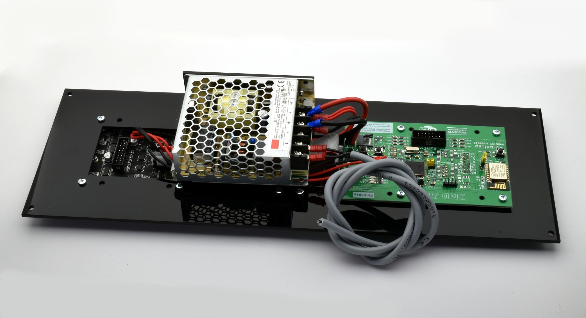
I hope assemble this week my first version of DMD ST32 board, and will test with my own firmware and with pin2dmd. If somebody want it, its an ALL in one board, connect direclty to led panel (do not need flat cable), load firmware and thats all, board provide empty no firmware pre-loaded, but very easy to load by USB.

My full assembled product also include power supply directly attached to frame plate with an Iron L shape and 4 screws, so do not need to think about where to put the power supply, product is full compact and clean installation. I will put pictures when available my board DMDST32, assembled and connected to led panels with power suply.

And like said Barto, Im not a company, I choose Pinballsp name to this activity about develop electronic devices.

Kind Regards.

001_(resized).jpg001_(resized).jpg
002_(resized).jpg002_(resized).jpg
003_(resized).jpg003_(resized).jpg
004_(resized).jpg004_(resized).jpg

DMD_006_(resized).jpgDMD_006_(resized).jpg

#41 8 years ago
Quoted from russdx:

I have been playing with the esp8266 recently, great little board cant beleave you can get wifi for $2 lol. How do you plan on using it with your firmware? Just for dfu? Or will you use it for uploading new colour data etc.
Not having to open your machine to replace a sd card or connect a usb cable for firmware updates is a huge advantage to your design.
Are you manual routing your pcb or using auto router? I much prefer manual routing as i love doing it and think you end up with a cleaner design at the end.

About WIFI, I plan use it first to upload wireless config and palettes from Cell phone and in next modification I will add option to upload also full firmware, but to do it I will must to add a bootloader to erase and write flash with new firmware and recompile firmware with special link script to relocate firmware to specific address in flash.

About PCB routing, some manually, some auto. I always route manual coupling capacitors 100nF for MCU and Quartz, rest auto. Yes manual routing is better, but when complex design require a lot of time, so only manual routing sensible components.

#42 8 years ago
Quoted from russdx:

Also noticed on your design (what looks like usb micro? On the far left) is this a vertical connector? How do you plug cable in with it in center of pcb? Same with the sd card does it open up or something and you place the card in and close it? Because a standard slide one wouldn't work? Sd card would hit the components?
Also noticed the right cap on your crystal has a trace going straight through it to the dmd connector. Its best not to have any high speed data lines near and certainly not through or under your Crystal as they can upset it.

Yes its a vertical USB connector, but I put Mini USB type B, not micro USB. About USB cable, I use a 90 angle degree, so connect right for vertical USB connectors. I have put it because of if horizontal USB connector can not connect correclty standar USB cable because of cable connector contact with frame plate because of PCB is under frame plate. When I put pictures with all assembled will see what I mean.

My micro SD card socket is ok, no problem about it. I have use it already in many of my designs, may put SMD components in front and SD card connect perfecty, do no hit components. Attached pictures about this socket in one of my designs with GSM and ESP8266 ESP12.

About trace trough capacitor, I do not have send PCB yet to manufacture, I must check it and modify something to improve it, thanks I will put some restrict rules to avoid that autotrace place tracks close or through those components of oscillator.

SD_card_002_(resized).jpgSD_card_002_(resized).jpg
SD_card_001_(resized).jpgSD_card_001_(resized).jpg

ScreenHunter_011_(resized).jpgScreenHunter_011_(resized).jpg
12359913_948561911890712_6880349959546435931_n_(resized).jpg12359913_948561911890712_6880349959546435931_n_(resized).jpg

#43 8 years ago
Quoted from rubberducks:

This looks like the board to have. Assuming it works, good work guys.
Does the in-house firmware support frame by frame colouring and pinball browser? If not, is it in the roadmap?

Thanks, today I will receive my first PCB version about DMDST32, will assemble it, test and will put pictures about it.

Yes, my firmware will support frame by frame colouring with keyframe and multiple palettes, and I think I will may provide already it in first version of product. Also I will add config with two buttons in board and config menu in display to select bright level and start mode instead of use USB and pc software. Next will be add WIFI support for config and update firmware, with an App in cell phone.

Also I want to test new Raspberry 3, to see if may even apply colouring to pixel level by frame, instead of replace bright level by color. This is a powerful board, 10 times faster than first Raspberry pi, so do not need FPGA to apply replacement of full frame by new colorized pixel by pixel. I will consult with my lawyers to see if some legal problems about patent, but I think no problem.

#45 8 years ago
Quoted from russdx:

Yeah i saw the new raspberry pi the other day it has built in wifi and bluetooth which is cool. I almost went down the raspberry pi zero route instead of a custom pcb. But they are near impossible to get hold of so pointless for a commercial product.
Ah i see so as long as you just have some small passives in front of that sd card your ok its like slighty risen
Yeah i spent a good few hours routing just the display header on my design and then reconfiguring the pinout so it matched my hardware so the traces where as short and direct as i could get them. Hardly had to jump layer either ill find a pic later.
I just love manual routing its insanely therapeutic (even complex designs)
Regarding the esp8266 do you just talk to it using uart with its standard AT firmware or do you put your own firmware on it?
I think i enjoy the hardware side of things more then writing the firmware designing pcbs and connecting different modules together making them communicate etc... Im coding all day at work so makes a nice change

About ESP8266 I have use it with AT commands, but I want try also to program it with LUA, seem easy.
Hardware - software, I was first professional software programmer for about 22 years, and about electronic design I think all my life, and years ago mainly to design and program microcontrollers based circuits, also some with RPY and Beaglebone Black.

Well, today I have receive first version of PCB for DMD ST32 controller board, this do not include yet WIFI, buttons for config menu and boot option, but its ok for first tests, load firmware, connect to led panels and full assemble product. I will assemble it between today and tomorrow.

Also I have receive PCB boards I have design for an Autocalibrated Eddy sensor, main circuit and printed coil. This do not need adjust never, itself calibrate each time that connect power supply.

And third board is for a friend that need it to connect inside an Xbox gamepad to control a big electric motor and up to 12 microrelays according with several data signals from gamepad.

DMDST32_(resized).jpgDMDST32_(resized).jpg
Eddy_AUTO_(resized).jpgEddy_AUTO_(resized).jpg
Xbox2_(resized).jpgXbox2_(resized).jpg

#47 8 years ago
Quoted from russdx:

How do you assemble the smd parts? do you solder them by hand or put down solder paste and use some sort re-flow oven?
Those boards look pretty cool. whats with the crazy shaped one lol??

I have two reflow oven, T962 and T962A and one stencil printer to apply solder paste. I order always stencil for each board, even some times I panelize boards to apply solder paste to several at time. So assemble prototypes is always very fast and easy. Also to solder THT I have a big solder pot. And some time I hope order a chinese Pick and Place machine, like this in picture attached, then will may even assemble some quantity of boards.

Last board has a special shape, because of its to put it inside an Xbox gamepad, and its the internal shape. I made so to may place all components, because of cliend added each time more and more components, last was a LIS331 accelerometer, more micro-relays and some SMD Leds.

horno_(resized).jpghorno_(resized).jpg

#50 8 years ago
Quoted from russdx:

wow your properly setup for making these boards have all the gear! I have to send my designs off for assembly as i just dont have the time or patients to assemble them my self hehe. Also the parts are just to damn small!!!!
How well do the stencil / re-flow ovens work? Is it pretty much stencil pcb, place your parts, reflow it and out pops a working pcb? or do u have to rework them a bit?

Final result with reflow oven is perfect if place correctly solder paste, its very important or will produce some shorts between pins in TQFP chips, though later may remove shorts easily with solder wick and soldering station. Also I check always TQFP chips with microscope.

To assemble prototypes and medium quantity of boards its perfect and cheap. For big quantities (more than 100 pcs) I send it to assemble to a company.

12657981_979909198755983_430482471124548709_o_(resized).jpg12657981_979909198755983_430482471124548709_o_(resized).jpg

#52 8 years ago

Today board assembled, I add also pictures about full product assembled, only need add two small wires red-black from controller board to power supply. Tomorrow test firmware, and practically all is ok and ready.

Im preparing also a new version that add WIFI, two butons to config from display with config menu, one external SPI Flash memory 2 Mega to store config data instead of use SD card, though I will keep SD socket probably to update firmware with bootloader, remove reset button, keep only one LED (enough to check data), remove round jack (board get voltage supply with two wires directly to power supply), remove Jumper mosi-miso (do not know why is this jumper, so as soon as I know what is the correct position I remove it), add Boot jumper to load firmware, Keep St-Link connector to program directly and to do DEBUG, replace horizontal USB connector by Vertical USB connector.

About firmware I will test with pin2dmd, though Im developing my own firmware, its easy. I will add a new feature with random multiple palettes by time and I will see if add or not Keyframe because of somebody seem that get very NERVOUS when see the word "KEYFRAME" and then inmediately send private message about PATENTS. I have check patents with my lawyers and there is no problem about it, ALL I will do about firmware will be legal and without infringing the patent law. Though use Keyframe do not infringe any patent, there are another ways to add more colors to same game with good results, I must to check it yet, I think even will be better than Keyframe and mask to variable data.

DMD_ST32_001_(resized).jpgDMD_ST32_001_(resized).jpg
DMD_ST32_002_(resized).jpgDMD_ST32_002_(resized).jpg
DMD_ST32_003_(resized).jpgDMD_ST32_003_(resized).jpg
DMD_ST32_004_(resized).jpgDMD_ST32_004_(resized).jpg
DMD_ST32_005_(resized).jpgDMD_ST32_005_(resized).jpg
DMD_ST32_006_(resized).jpgDMD_ST32_006_(resized).jpg
DMD_ST32_007_(resized).jpgDMD_ST32_007_(resized).jpg
DMD_ST32_008_(resized).jpgDMD_ST32_008_(resized).jpg

#54 8 years ago

I do not know yet real maxim current that need those two led panels. I have ask to chinese distributor and they say between 7 and 10 Ampere. I thought that really do not need so big current.

When I connected Discovery and led panels to my power supply with voltimeter and amperemeter, current consumption was 500 mA with the main test screen. At any rate power supply must to may provide maxim current if some time all leds are on.

If we think that each led may need 20 mA, there are 128 pixels by row and 3 leds by pixel (red, green, blue), its 384 * 0.020 = 7.68 Ampere, really will be less by row because of work at 1/16 Scan, but if all rows are with all leds on, then really need more than 7 Ampere. So its possible that really need a power supply 10 Ampere. There are power supply of 7, 8 and 9 Ampere, but price difference is very low.

At any rate I will test it with my laboratory power supply with voltimeter and amperemeter, runing a game with virtual and real pinball.

#58 8 years ago
Quoted from Kneissl:

Are any of these boards for sale somewhere?

Yes, my controller board DMD ST32 is already avaible, tested and working 100%. Pictures attached about product full assembled installing my controller board, its an ALL in one board, this include all and connect directly to led panels.

My controller board DMDST32 full assembled, price is 45 euros + shipping.
Display full assembled with power supply 10 A, 164 euros + shipping for one unit, 157 Euros + shipping for 5 units.

Display full assembled and controller board do NOT INCLUDE firmware preloaded, but its easy to load it, its compatible with pin2dmd open source version. At any rate Im preparing my own firmware with new features, and also a new version of my controller board that add WIFI to config wireless from cell phone, buttons to config with config menu in display (do not need PC software by USB), remove some leds, remove reset button, remove miso-mosi jumper. And about firmware, add new features like random multi palette by time and some more Im preparing.

DMDST32_005_bis_(resized).jpgDMDST32_005_bis_(resized).jpg
DMDST32_003_(resized).jpgDMDST32_003_(resized).jpg
DMDST32_003b_(resized).jpgDMDST32_003b_(resized).jpg
DMD_ST32_002_(resized).jpgDMD_ST32_002_(resized).jpg
DMDST32_004_(resized).jpgDMDST32_004_(resized).jpg
DMDST32_008jpg_(resized).jpgDMDST32_008jpg_(resized).jpg
DMDST32_009bj_(resized).jpgDMDST32_009bj_(resized).jpg
DMDST32_009jpg_(resized).jpgDMDST32_009jpg_(resized).jpg
DMDST32_010bjpg_(resized).jpgDMDST32_010bjpg_(resized).jpg
DMDST32_010jpg_(resized).jpgDMDST32_010jpg_(resized).jpg
DMDST32_013jpg_(resized).jpgDMDST32_013jpg_(resized).jpg
DMDST32_016jpg_(resized).jpgDMDST32_016jpg_(resized).jpg
DMDST32_020jpg_(resized).jpgDMDST32_020jpg_(resized).jpg
DMDST32_021jpg_(resized).jpgDMDST32_021jpg_(resized).jpg
DMDST32_022jpg_(resized).jpgDMDST32_022jpg_(resized).jpg
DMDST32_023jpg_(resized).jpgDMDST32_023jpg_(resized).jpg
DMDST32_025jpg_(resized).jpgDMDST32_025jpg_(resized).jpg

#62 8 years ago
Quoted from Crash:

Looks great!! Is this a microcontroller based platform or is it ARM based running some form of Linux? For simplicity and startup times it would be nice if there is some form of programmable microcontroller option.

Hello Crash.
Its based in same microcontroller that install the Discovery board, the ARM STM32F407 TQFP100 pin. This can not run Linux, to do it need some powerful based SOC like Raspberry, Beaglebone Black or similar.

May install pin2dmd Open source, and because of sources are available may modify and compile it with Coocox, or better with Eclipse + GCC. About load firmware its very easy, Im preparing second version of my controller board with a boot jumper, then may enter in bootloader mode and load any firmware by USB. As soon as available I will put full instructions to do it, its very easy.

#63 8 years ago
Quoted from Coyote:

Same as Lucky's board -
It's a microprocesor - ST STM32 processor. There's no noticeable 'bootup' time - apply power, and the splash screen immediately comes up. If the FW was open source, you could modify the FW and hide the splash screen and go directly to displaying pinball input.

Yes, exactly.

#64 8 years ago
Quoted from russdx:

Use xdmd or something to clear the splash screen once pc booted?

Do not need to do it, pin2dmd sources are available, may modify it to avoid splash screen or even put your own splash screen.

#66 8 years ago
Quoted from russdx:

Only the old source is a available all there new stuff is closed source.

No problem about it, I will modify current sources to provide new features, like Keyframe, WIFI, buttons to config from Display with config menu (do not need USB and PC), PC Soft. Editor to colorize frames by Keyframe, support for big displays SEGA 192*64 (with 1/32 Scan panels), etc...

Common Creative license allow that anybody modify sources, if provide sources modified, and I will do it, so no problem about closed official new versions, I will modify current open source version with no key code to activate it, so will be also free and open for everybody.

Add keyframe is very easy to colorize by frame, and I think add new features like random multipalette by time that may be even better than colorize by Keyframe and no patent problems.

Dont worry about it, new features will not be closed with key activation to current sources modified by me, and all legal and according with Creative Common License.

#67 8 years ago

My new controller board version DMD ST32 is ready to send to manufacturer.

This add/modify/remove following:

1.- Add WIFI (optional) to config display wireless from Cell phone with App.
2.- Add two buttons to config display from controller board, show a config menu in display, do not need use USB and PC software.
3.- Only keep one Led for data transmit check, rest really do not need so remove.
4.- Remove RESET button, to reset board simply remove power supply.
5.- Remove MOSI-MISO jumper, do not need it.
6.- Remove round jack, get voltage with two wires directly to power supply.
7.- Add a 2 Megas Flash memory chip by SPI to store config, cheaper than use SD card though keep micro SD card socket to provide updates
8.- Add BOOT jumper in board to may load firmware or updates by USB with free software provided by MCU manufacturer, its mainly to install pin2dmd firmware if somebody want to do it, do not need a programmer

ScreenHunter_002_(resized).jpgScreenHunter_002_(resized).jpg
ScreenHunter_003_(resized).jpgScreenHunter_003_(resized).jpg

#70 8 years ago
Quoted from lucky1:

Sounds like a good plan as long as the software also stays non commercial, which is also a part of the license.
I love the idea of retiring and having time for something new if somebody with better skills takes over.
I have some motorcycles here which are waiting for a restoration.
When will the second version with wifi be available ? I think I have to play with that.
About the 192x64 displays, I already made a test run with 1/32 scan panels and the mpu is fast enough
but memory could become a problem. Was thinking to change to the 429 disco board for that.

Hello lucky.
About board with WIFI its already designed, I will send to manufacturer probably next week, and I will receive it in about 7 days. If you provide me your full address I will ship you one board for free.

About use 429 instead of 407, good idea, I will check it. I have here several samples I requested time ago to ST about 429, with 100, 144 and 176 pins. If 429 TQFP 100 is full compatible pin to pin with 407 I may solder a 429 in same board instead of 407, I will check it.

But about use Discovery 429, it install a 144 pin, I have one here, with touch screen, a 64Mb SDRAM, accelerometer, a lot of hardware that really do not need for this application but pay for it. It think its better a custom board with only hardware that really need, I think I may install a 429 in my current board and in next version with WIFI, so increase speed and RAM, but only increase a little price to replace 407 by 429, I test it as soon as possible and confirm.

IMG_20160311_104138_(resized).jpgIMG_20160311_104138_(resized).jpg

ST_tabla_(resized).jpgST_tabla_(resized).jpg

ST429_disco_003_(resized).jpgST429_disco_003_(resized).jpg

#71 8 years ago

About freight cost to ship my products, controller board or full assembled display, I have check it with my courier company and these are my freigh cost. I think are really cheap, mainly to ship to USA, all by courier with tracking number and door to door service. Courier that ship in USA is TNT.

For example, one full assembled display has a weight of 1062 mg, must add weight of package, then take freight cost for 2Kg and its 39.5 Euros freight cost by courier with tracking. If some people in same country may mix orders to ship in one package will be cheaper than multiple shipments.

About payment its ok by TT or Paypal.

ScreenHunter_004_(resized).jpgScreenHunter_004_(resized).jpg

#74 8 years ago

There are led panels 64*64 1/32 Scan P2.5, I want to try it, with 3 panels P2.5 get a 192*64 led panel same dimensions that original SEGA.

And about replace 407 processor, I have check it and best option is replace 407 by 427 instead of 429. STM32F427 is cheaper than STM32F429, but both offer same speed 180 Mhz and same amount of RAM 256K. STM32F429 is more expensive because of include a TFT LCD controller that its not useful for this application.

So replace 407 by 427 mean increase speed from 168Mhz to 180 Mhz, and increase RAM amount from 196K to 256K. I have order several STM32F427 to test it with my controller board, I think bouth 407 and 427 are full compatible pin to pin, so do not need design a new PCB, simply replace each other. About price only increase it in about 1.4 Euros, so small increase of price but better performance and memory amount for future applications like support SEGA 192*64 displays or multiple color palettes. If all test ok I will install it in my new controller board with WIFI.

#79 8 years ago
Quoted from Axl:

would it be possible with this soulution to use LCD panels?
Axl

No, its not possible. This hardware do not has enough power to control a TFT LCD panel, to do it may use a SOC based like Raspberrry or Beaglebone Black with HDMI output.

#81 8 years ago
Quoted from russdx:

These make great psu for these panels
http://m.ebay.co.uk/itm/191733870857
I have been running the 5v 10a my self without problems but you could prob drop to the 8a or *maybe* 5a
Its only when these displays are full brightness on white with every pixel lit they draw maximum current. Most people run them at 50% or lower and very rarely all pixels are lit so you dont need a mega psu.
I will connect a meter at some point and run some tests see what *real world* currents it draws when playing games in different colours and brightnesses.

5V 10A same price than 5V 20A ??, strange, probably its a mistake, for 20A its a good price, perfect for SEGA 192*64 display.

I do not know what is real power comsumption with all Leds ON, I always have think that 10 Ampere is too much, but until I check it with my amperemeter will not know. Currenly I install 10A power supply, but even if may work with 8A power supply, price difference between 8A and 10A power supply is very small, so finally install in any case a 10A power supply.

OK, if you check real current comsumption, warn about it, I will do too. At any rate I may modify sofware to play a test screen with all Leds ON, so will know real current comsumption, because of in a game screen its variable so will be hard to know when all leds will be ON and even if some time happen it, will be for a very short time, then hard to know the peak current consumption.

I only may suppose, if each led need 20mA, there are 128 leds by row, 3 colors Red, Green, Blue, then its 384 leds * 20mA = 7.68A.

#83 8 years ago

Well this is my last design for controller board, I think ready to send tomorrow to manufacturer and get it in about one week.

According with lucky1 I have add 2 x octal buffer 74LS245 to avoid some random pixel problems when used with real pinball, finally keep all the 4 leds and add text for function of each one, so blue led print DATA, red led is ERR, Orange and Green are KEY1 and KEY2.

Board may install optionally a WIFI ESP8266 ESP12 module and a Flash Memory chip with 2Mega to store config. I have must to increase a little size of board to may add those new chips, and install small SMD leds 1206. USB now is vertical to connect a 90 degrees cable. The WIFI module is really a very powerful device than include an ARM processor that may be programmed in LUA, board include a jumper to program it by Serial UART. Board install an ST-LINK compatible connector to program or DEBUG MCU.

This board will may install several different ARM microcontroller:
========================================
1.- STM32F405, 168 Mhz, 196K RAM, 1 Mega flash, cheaper than F407 and for current pin2dmd, full compatible.
2.- STM32F407 same that currently install Discovery, 168 Mhz, 196K RAM, 1Mega flash program.
3.- STM32F427, 429, 437 or 439, improve speed to 180 Mhz and RAM amount to 256K, 1-2 Mega flash program.
4.- Even may intall the Super Powerful STM32F7 that run at 216 Mhz with RAM 320K, 1-2 Mega flash program..

ScreenHunter_003_(resized).jpgScreenHunter_003_(resized).jpg

ScreenHunter_004_(resized).jpgScreenHunter_004_(resized).jpg

#85 8 years ago
Quoted from toibs:

Let me know when you have these new boards for sale - I want one with the 32f7 and wifi and panels - the complete kaboodle

Ok, I will receive it in one week.

#86 8 years ago

Today I have receive 3 units about the microcontroller 427, I have install it in my current controller DMD ST32 and work perfect with pin2dmd. This is faster than Discovery 407 MCU and increase RAM to 256K. I will check also with the F7 at 216Mhz, faster than any F4 and with 320K RAM.

427_(resized).jpg427_(resized).jpg

#97 8 years ago
Quoted from russdx:

200mhz do you need such a fast processor to update the dmd modules? DMA on smaller f4s should be fast enough?
Or is it more when you come to do checksums on frames for colouring and other fancy stuff you need the extra power?

I think will need a powerful system to apply keyframes and colorize with multiple palettes. At any rate board is always same, only that may install several different microcontrollers, 405, 407, 427, 429, 437, 439 and the fastest F7.

Even for current firmware, the 405 is better and cheaper than the 407, because of 407 install a Camera driver not useful for this application, and 405 fith same speed and RAM amount do not include it and so its cheaper.

#98 8 years ago
Quoted from lucky1:

There is only one thing that is better than power - more power !
Did you change the code for different clocking otherwise you are running at 168mhz.
The transfer from the pinball or to the DMD is not the problem. These speeds are limited by hardware anyway (bus speed).
Recognition is hardware accelerated and may not be a problem either, but that depends on the amount of variants you want
to check. Realtime picture processing (colorization) is currently the most mpu and memory intensive but we are currently
working on an faster routine for that.

Do not know, I frined mine has test it, I suposse he will have modify clock frequency in sources, but do not know. At any rate like I said, the good is with same board may install several diferent MCU according to the needs.

I have order already severa F7 and 405 to test it too.

#99 8 years ago
Quoted from emkay:

Yeah, I do too. I've been on the fence but I need to jump in the pool.
How much is the full kit shipped to the US?

Full assembled display for one unit price is 164 euros and freight cost to USA by Courier with tracking is 39.5 Euros. Current currency exchange Euros/USD is 1.11.

Only controller board with 407 processor (no wifi), is 45 euros + shipping.

#100 8 years ago
Quoted from Pinterest:

Yeah, I'm down for the new board fully equipped also where will it come in price wise?
I want this chip with a petabyte of memory!
BrainPower_(resized).jpg

Price will be similar to current 407, but may add options like WIFI, faster processor, Flas memory chip. Even with 405 processor will be cheaper for basic board. WIFI may be add 3-4 euros, Flash memory add 2 euros, faster 427 processor add 3-4 euros.

#101 8 years ago
Quoted from flecom:

how much does just a controller weigh?

One board is very light, may be even may apply a freight cost for 0.5 Kg that is the cheaper by Courier, about 25 USD to USA with tracking and door to door service.

#102 8 years ago
Quoted from pinballwil:

More power is great but make shure its not overheated or needs a fan installed, i hate pc fans they always stops working after some thime.

No problem about it, these microcontrollers almost not heated. Only when start to use SOC based like Raspberry, Beaglebone or similar may need add some heat sink, and even for a SOC do not need a fan.

#103 8 years ago
Quoted from pinballwil:

More power is great but make shure its not overheated or needs a fan installed, i hate pc fans they always stops working after some thime.

No problem about it, these microcontrollers almost not heated. Only when start to use SOC based like Raspberry, Beaglebone or similar may need add some heat sink, and even for a SOC do not need a fan.

#104 8 years ago
Quoted from pinballwil:

More power is great but make shure its not overheated or needs a fan installed, i hate pc fans they always stops working after some thime.

No problem about it, these microcontrollers almost not heated. Only when start to use SOC based like Raspberry, Beaglebone or similar may need add some heat sink, and even for a SOC do not need a fan.

#105 8 years ago
Quoted from pinballwil:

More power is great but make shure its not overheated or needs a fan installed, i hate pc fans they always stops working after some thime.

No problem about it, these microcontrollers almost not heated. Only when start to use SOC based like Raspberry, Beaglebone or similar may need add some heat sink, and even for a SOC do not need a fan.

#106 8 years ago
Quoted from pinballwil:

More power is great but make shure its not overheated or needs a fan installed, i hate pc fans they always stops working after some thime.

No problem about it, these microcontrollers almost not heated. Only when start to use SOC based like Raspberry, Beaglebone or similar may need add some heat sink, and even for a SOC do not need a fan.

#107 8 years ago
Quoted from pinballwil:

More power is great but make shure its not overheated or needs a fan installed, i hate pc fans they always stops working after some thime.

No problem about it, these microcontrollers almost not heated. Only when start to use SOC based like Raspberry, Beaglebone or similar may need add some heat sink, and even for a SOC do not need a fan.

#117 8 years ago

Yes, a 64*64 1/32 Scan, and its even cheaper than 64*64 1/16 that use for current 128*32.

#118 8 years ago
Quoted from pinballwil:

Great i skip the color dmd and go for the pinballsp kit soon.

Thank you.

#121 8 years ago

Preparing my own firmware. Splash screen, next screen will display Firmware version, SD card status, Startup mode, WIFI status, Bright level, Palette and will allow enter in config menu with buttons in controller board or WIFI from cell phone, tablet or Pc computer with internet browser.

DMD_ST32_003_(resized).jpgDMD_ST32_003_(resized).jpg
DMD_ST32_004_(resized).jpgDMD_ST32_004_(resized).jpg

#123 8 years ago
Quoted from russdx:

What camera do you use? it captures the colours of these displays very nicely something i am really struggling with my self.

I use a Nikon camera, and still am not very happy with the results, seen in person the colors, brightness and contrast are much better. At any rate with cell phone camera the results are worse.

#126 8 years ago
Quoted from russdx:

Hows your firmware coming along?

First need my new controller board, just tomorrow I receive PCB by DHL. Assemble it and start with my firmware tests, also will try to update pin2dmd open source to add support for WIFI, Config Menu in Display, Store config in Flash chip (do not need SD card), Random Multipalette by Time, SEGA display (with 427 or F746 MCU), etc...

Also I have here already several microcontrollers 405, 427 and F746, I will assemble three boards each one with a different MCU to test it. Im also waiting for 160*160mm 1/32 Scan led panels for SEGA displays.

#127 8 years ago
Quoted from iEatHands:

If you can put a RGB LED kit together for a SEGA 192x64 DMD it'd be a day 1 purchase for me when you release it!

Sure, Im working about it.

#130 8 years ago

.

Today received PCB about new controller board with WIFI, config buttons, boot jumper, Flash 2Mb chip and two chip buffers to improve real pinball performance.

I will assemble and test new controller board along this week, with four microcontrollers, 405, 407, 427 and F746. Do not know why text "RGB LED Controller" is not printed, I have claim to manufacturer.

DMD_ST32_controladora_005_(resized).jpgDMD_ST32_controladora_005_(resized).jpg
DMD_ST32_controladora_002_(resized).jpgDMD_ST32_controladora_002_(resized).jpg
DMD_ST32_controladora_003_(resized).jpgDMD_ST32_controladora_003_(resized).jpg

#132 8 years ago
Quoted from rubberducks:

Wouldn't it benefit everyone if lucky1 and pinballsp were to work together on the software / firmware? many hands make light work, and I'm sure the two of you (or two teams) could come up with something superior to either in isolation ...

I try to collaborate, but with closed sources its not easy. I will add updates to V1, then hope may get access to V2 sources. At any rate Im also developing my own firmware.

My updates will be add WIFI support, config buttons with config menu in display, option to store config and palettes in Flash chip (do not need keep connected a SD card), random multipalette by time, SEGA 192*64 support with 427 or F746 microcontroller in board and by hardware Boot option to upload firmware without programmer. Also I have an encrypted booloader to may provide updates encrypted so nobody may disassemble Hex file.

Also, great work. This looks like it's going to be the go-to solution.

Thank you.

Re: the gel film .. would probably be a good idea to offer it. It ought to improve perceived contrast quite a bit, depending on how effective it is at eating bleed and bloom.

Yes, good idea.

#143 8 years ago
Quoted from rubberducks:

I'm sure someone will be willing to write apps for Apple / Android if you guys are willing to collaborate Ubuntu Touch would probably be even easier with their web based Scopes. That's the beauty of being open. A basic framework surely wouldn't be too difficult to set up.

Well, its not indispensable develop an App to access via WIFI to this device. The module I have install may run like a Web Server, so may access from any internet browser to local IP by WIFI and config device or upload files, its easy develop an HTML web page for ESP8266 WIFI module, so in that web page may put buttons to select palette, slider to select bright level, buttons to upload updates, etc...

I must to check it yet, but this WIFI module may be programmed in his own LUA language, then do not need develop an App for cell phone, only open your internet browser, select the local IP of WIFI and access to a web page stored in controller board WIFI module.

I do not have experience developing JAva applications for cell phones, but I have develop many web pages in PHP and HTML, so program ESP8266 like server and store a web page to config controller board with any cell phone, tablet or PC computer with WIFI must to be easy.

Also may do live stream , though I do not have experience about it.

#147 8 years ago

.

Already assembled four prototypes for new DMD ST32 LED panel controller board. Two with WIFI and F427 microcontroller, one with F407 and not WIFI and one with F405 and not WIFI.

Tomorrow I will star to check firmware with these four boards, I want to see that F427 and F405 work fine, also this new version include two 74LS245 buffers to improve performance with real pinball, so I want check it too.

Current features of this controller board version of DMD ST32 are following:

1.- Ful compatible Discovery hardware based firmware.
2.- May install optional, WIFI module for wireless config, updates, palettes, new firmware versions, etc... This module may be controlled with AT commands or programmed in LUA language by serial port in board.
3.- Three Buttons for config in display with Menu.
4.- 2 Mega Flash Memory chip in board, to store config, palettes, keyframes, etc...
5.- Boot mode to load firmware by USB, with BOOT jumper in board
6.- St-link connector to program and DEBUG microcontroller with JTAG/SWD (may use ST-Link V2 programmer/debuger, its very cheap)
7.- Four leds, with print texts in board (ERR, DATA, Key1, Key2)
8.- Micro SD card socket.
9.- May install five different STM32 microcontrollers; F405, F407, F427, F429, F745/6. F427, 429 and 745 are the powerful to support future updates for SEGA 192*64 big displays, Colorize by Keyframe, Random Multipalette by time, etc...
10.- RC filters resistors/capacitors to improve pinball real data input.
11.- All in one board, connect directly to led panel input data, do not need add any additional board or flat cable.
12.- USB Mini B port VERTICAL, for config and updates from PC computer.
13.- Keep MISO-MOSI jumper, but like a solder jumper, by default solder in position 1.
14.- Optional, add two 74LS245 buffers to improve output data to led panel.
15.- Board protected against polarity inversion.

Controladora_DMDST32_009_(resized).jpgControladora_DMDST32_009_(resized).jpg
Controladora_DMDST32_007_(resized).jpgControladora_DMDST32_007_(resized).jpg
Controladora_DMDST32_008_(resized).jpgControladora_DMDST32_008_(resized).jpg
Controladora_DMDST32_010_(resized).jpgControladora_DMDST32_010_(resized).jpg
Controladora_DMDST32_012_(resized).jpgControladora_DMDST32_012_(resized).jpg
Controladora_DMDST32_002_(resized).jpgControladora_DMDST32_002_(resized).jpg
Controladora_DMDST32_006_(resized).jpgControladora_DMDST32_006_(resized).jpg
Controladora_DMDST32_005_(resized).jpgControladora_DMDST32_005_(resized).jpg
Controladora_DMDST32_004_(resized).jpgControladora_DMDST32_004_(resized).jpg
Controladora_DMDST32_014_(resized).jpgControladora_DMDST32_014_(resized).jpg
Controladora_DMDST32_001_(resized).jpgControladora_DMDST32_001_(resized).jpg
Controladora_DMDST32_015_(resized).jpgControladora_DMDST32_015_(resized).jpg

#158 8 years ago
Quoted from lucky1:

Great Luis ! Can´t wait to test the 427 with pin2dmd. Already found the "perfect" firmware for the Wifi.
Should be pretty easy to get this running.

Ok, thanks Jörg. Good if you have already wifi source code for this ESP-12.
Im testing boards now, as soon as all is ok, I will send three boards to Dominik, then he give two for you.

#159 8 years ago
Quoted from pinballwil:

looks great, awesome but the soldering looks a bit to hot here and there.
But that is a hand made prototype i think.

Yes, these are prototypes, but even so with an ultrasonic cleaner, board may look perfect. At any rate I do not solder it by hand, but in an oven reflow, and resins need to be cleaned with ultrasounds to offer a good look board though work perfect too.

#160 8 years ago
Quoted from rubberducks:

Wouldn't it be a good idea to only offer the more powerful processors? Or THE most powerful one. I assume we're only talking a few Euros more, and who knows what future features you or others may want or need to add? Plus with one SKU support and problem solving and testing are easier, and there's no segmentation and complete feature and performance parity. Standardisation makes things much easier in getting this off the ground as a standard and offering a competitive product, and really removes potential confusion for buyers.

There's no reason for it not to become the go to solution full stop. It's far more elegant and featured than ColorDMD or SmartDMD ever were. The community just needs to get behind it, and it's great that despite initial enmity, lucky1 and Luis are now collaborating.
Not only would we then have a better solution than anything now available, but it'd also force the market leaders to move forward and hopefully innovate and lower prices rather than hiding behind assinine patents that will never cover most of the world and would be unlikely to retain validity if tested in the home market.

Yes, probably all boards will install F427 microcontroller, because of I have get a very good price to order it in quantity. Price difference between F407 and F427 is only 1.3 USD, so I think will be better install only F427. At any rate I must test it yet to confirm its 100% compatible.

There is also a more powerful solution with F745 or F746 microcontrollers, but higher price difference. These are a very fast microcontrollers ARM 216 Mhz, 1Mb Flash Memory ,320K Ram. May be for future special features that require very fast and powerful processor. Current PCB may install also these microcontrollers without modify hardware.

#162 8 years ago
Quoted from rubberducks:

How much more are the 745 or 746? Probably not that much more? I can't stress how much better it would be to have one standardised platform, and one which will be future proof for quite some time. If you can forsee a situation where the extra speed and resources could be useful, then it's best to go for it.

F745 not available in China, they order to USA and resell. So price is same that order in Europe, and its double price than F427.

Finally I think I may offer board with two processors, F427 or F745/F746. With F745/F746 may increase price in about 10 Euros, but I must test it yet to see if its full compatible with current microcontrollers.

#163 8 years ago

.

Some more pictures, these about USB.

For this kind of Vertical USB connector, I suggest use this 90 degree cable. Mainly if you must keep it connected for long time, like happen in a virtual pinball, because of a standar USB cable may break the solder points of vertical USB connector.

dmd_st32_008_(resized).jpgdmd_st32_008_(resized).jpg
dmd_st32_004_(resized).jpgdmd_st32_004_(resized).jpg

#165 8 years ago

.

I have here one STM32F746 chip, I will assemble one Controller Board with it and will test.

Its a very powerful ST microcontroller, F7 compared with F4, double its performance, 462 DMIPS vs 225 DMIPS. This may be interesting to apply keyframes and colorize with real pinball.

ST32_007_(resized).jpgST32_007_(resized).jpg

stm32_sc1169_(resized).jpgstm32_sc1169_(resized).jpg

#170 8 years ago
Quoted from lucky1:

If we change the clock settings we have to adjust several timings again. The F7 is nice but would behave different, i think. I will ask Steve (pin2dmd editor) to share his opinion here also.

I suspected about that, if some software timings are calculated according with clock frequency, if modify clock will need modify source code or display will not work properly.

So for current firmware must keep same clock for F427 and F7 though microcontrollers may run faster until create new firmware version specially for F427 and F7 with properly timings and faster clock (180Mhz and 216Mhz).

#174 8 years ago
Quoted from Coyote:

i can answer this part, at least - I use it to power both the LED panels and the STM board and shield. (It powers everything for the display.)
I'd be curious how much more amperage this board would take with the stronger processor, wifi, etc. That may push the whole system over 4a.

4A is enough to provide power supply to two leds panels ??. Currently I install a 5v 10A power supply, and seem everybody suggest minimal 6-7 Amperes. Chinese provider replied to me that each panel need about 3-4 Amperes, so two panels will need 6-8 Amperes.

Microcontroller need a few mA, probably about 60-80mA, and WIFI about 300-400mA but only when active, can dissabled it from microcontroller with an AT command. Therefore when the controller board works to get the animations on the display, only need about 60-80mA. When microcontroller run faster will need a little more mA, but not much more.

#179 8 years ago
Quoted from Coyote:

In the test I ran - full brightness, white color, on TZ over two 30-min games, the amperage for EVERYTHING (both panels plus controller boards), there was never more than 2.3A drawn. (2.28a, I believe, but I rounded up.) This included LITZ mode on one game, and powerball on both. (Heavy animation, bright lit, etc.) This did not have any frame-keying done, no palette switching, etc. And, in case it matters, I'm also using the PinLED display driver board, which Lucky can attest, uses a different timing mode than normal WPCs. I doubt that a different timing mode, however, can over double the amps drawn.

Very interesting, I never thought that two led panels may require 10 Amperes, do not understand why all I have read suggest install a 10A power supply, when may work perfectly with a 5A power supply, that is cheaper.

I want test it, with ALL leds ON, probably this never happen with a real game, but in theory its possible all leds ON, and this will be the real maximum amperage that may require the led panels. I will modify firmware to run a test that put all LEDS ON to know about it.

At any rate, I have checked price difference between 5A and 10A commercial power supply and its only 2 Euros en Europe. And price from China for a 10A power supply is only 6 USD, so probably it is not important put 5A or 10A power supply because of price is very similar. I do not know how much is your cost, but if a full assembled power supply 5V 10A has a price of only 6USD, do not know if worth to manufacture and assemble by hand.

#189 8 years ago
Quoted from rubberducks:

FPGA would be a LOT more expensive most probably ... also, how many people potentially interested in writing software or adding firmware features are familiar with what FPGAs would require as opposed to ARM these days?

Certainly its hard work with FPGA, I have some experience with VHDL and Spartan based boards, but not so easy like work with C/C++ language.

There is an easier option with Raspberry or Beaglebone Black. I have do many developments wih Beaglebone Black, easy to program with QT Creator + GCC and with enough power to work with keyframes to replace frame by frame with new colorized pixel by pixel.

It is even possible to reuse part of the STM32 source code for new development with Beaglebone Black or RPY, both have also SPI and I2C ports, more I/O ports in BBB. At any rate, cheaper with STM32, and may be with F7 will may do advanced colouring.

#190 8 years ago
Quoted from Crash:

Has anyone ordered some 64x64 panels? Luis is 192x64 support in your firmware coming in the near future? I have a dying plasma and would like to buy a kit from you if it's in the plans.

Yes, I have order 3 panels 64*64 1/32 Scan, hope receive it in about one week, and then will start with firmware tests.

I think that pinout of data connector is same than 160*80 mm led panels, so probably will may connect same controller board, though the frame to fix the board seem has not same holes to fix them with screws.

This weekend Im testing controller board with F405, F407 and F427 MCU.

#193 8 years ago
Quoted from toibs:

@pinballsp - Which panels would you recommend?? If you can post a link i'll get a couple ordered (for standard display size 128x32).

Most of led panels providers are chinese available in Aliexpress. Seem most of people order to Angela but I received several defectives and she is not so cheap like another providers.

And avoid the 64*64 1/16 scan because of though may split the led panels in 2 x 64*32, can NOT split the frame and if try to cut it the look is very poor.

#194 8 years ago
Quoted from russdx:

FPGA are perfect for this sort of thing they would scan those leds at crazy speeds without breaking a sweat. But as others have mentioned they are far more expensive and complicated to work with. Not sure id want to try and get a usb stack working on one?
One of my pinDMD2 prototypes was a Altera cyclone fpga with a high speed FTDI for usb coms. The thing was amazing it could support frame rates upto 120fps no flickering or tearing. BUT the BOM cost per board was insane far cheaper just to use the stm micro controller which did a good job at all tasks for quater of the cost.
I would like to play with the new fpgas that have the arm processer built in. You could have all ur control code there and usb coms. And just hsve a led scan module in the fpga side which only job is to scan the leds. Still cost a bit but far easier to work with. You can also get arm softcores but think you have to pay licence if using comercially?

Cheaper than FPGA are SOC like Raspberry or Beaglebone Black. And about MCU core for FPGA I think also its expensive, or may you try to develop your own MCU core.

I think the cheap and faster alternative to microcontrollers are Raspberry and Beaglebone Black SOC boards. Current Raspberry 3 seem very powerful, but even with before versions sure may run a very fast system to apply keyframes and advanced colouring.

May be I will try to do something with Beaglebone Black. Or try if STM32F746 has enough power to do it too, so keep current hardware, simply replace MCU and improve software.

#197 8 years ago
Quoted from Crash:

IMO I would prefer Luis's clean single board solution that is running software specifically designed for it. I really don't like Linux-based solutions for basic applications like this and it takes time to boot, you have to be careful with the SD card, etc.

Yes, you are right, all SOC boards like RPY are slow to boot.

I hope that my controller board with an F746 MCU has enough power to work with keyframes and pixel by pixel colorized pictures. And to store new colorized pictures to replace original, may use an external parallel eprom to get fast access, so may provide a cheap and powerful system to work with full and detailed colorized animations.

Also I want to check the Chrome-ART Accelerator and DMA2D system that include F427 and higher ST references, to control directly a TFT display, or even if may use it to improve LED panels control for advanced colouring.

At any rate a solution based on microcontroller, always will be cheaper than FPGA and faster to boot than SOC boards. I think with Cortex M7 microcontrollers like F746, F745, F756, F767, will may do a cheap and very powerful system.

#202 8 years ago

ScreenHunter_030_(resized).jpgScreenHunter_030_(resized).jpg

ScreenHunter_031_(resized).jpgScreenHunter_031_(resized).jpg

#204 8 years ago

.

Testing new controller board with F427 microcontroller and pin2dmd v1. Do not have recompile sources, simply load firmware. I think that buffers improve stability of screen. But need check about USB why Windows say "Device Unknown".

About full assembled DMD and controller board prices, I will calculate again, because of now I have better prices about microcontrollers, power supply and led panels, so may offer cheaper price. Also I have a new frame laser cuted in black acrylic, so high quality.

DMD_427_test_001_(resized).jpgDMD_427_test_001_(resized).jpg
DMD_427_test_002_(resized).jpgDMD_427_test_002_(resized).jpg
IMG_20160405_172051_(resized).jpgIMG_20160405_172051_(resized).jpg

#206 8 years ago

Thanks Joerg.
Unfortunately I made a mistake in the USB connector, it is wrong routed, all the 5 pins are inverted in PCB, so I must to do it again, I have send today new amend design to manufacturer, hope receive it in about 7 days.

At any rate I may load firmware with ST-Link Programmer by JTAG and work, but I can not config board because of USB do not work, so if activation key require USB then can not test it with this wrong board.

Yes, F405 board work very well too, exactly like F407, and its cheaper because of do not include Ethernet and Camera controller, not useful for this application. I think that buffers improve screen, seem its more stable, I like it, I think will install in all boards, I have get cheap price for 74HCT245 in quantity (TTL compatible 74LS245, but cheaper).

And I have get also very good price for F427 in quantity, so I think I will install only F427, because of price difference between 405 and 427 is only 1.4 USD. Probably only will be optional WIFI and Flash chip.

#208 8 years ago
Quoted from russdx:

Can you just cut up a usb cable and swap the wires around to correct the routing bug for testing?

I thougth about it, but though I may modify cable to connect correctly D+, D-, ID and GND, there is one pin of microcontroller connected to VBUS in schematic but by mistake of USB socket its really connected to ground of PCB, so I can not amend it though I modify manually wires of USB cable.

May be USB work without connect this pin, but I have damage already one board because of wrong USB in PCB, now this board when connect, microcontroller get very hot, though firmware run.

#209 8 years ago

.

Just today I have receive LED panels, most 160*80mm to do standar 128*32 DMD, but also I have receive 3 panels 160*160mm 1/32 Scan to do SEGA 192*64 DMD.

I mut to check it yet, but surprise me that there are only 3 letters A, B, C to address rows, instead of four letters A, B, C, D, so understand that internally some lines are really split in 2 x 64 pixels but connected in same line for shift register. I must prepare some firmware test to see how this data bus scan rows-cols.

DMD_160160_003_(resized).jpgDMD_160160_003_(resized).jpg
DMD_160160_002_(resized).jpgDMD_160160_002_(resized).jpg
DMD_160160_004_(resized).jpgDMD_160160_004_(resized).jpg
DMD_160160_006_(resized).jpgDMD_160160_006_(resized).jpg
DMD_160160_005_(resized).jpgDMD_160160_005_(resized).jpg

DMD_160160_001_(resized).jpgDMD_160160_001_(resized).jpg

#214 8 years ago

Some people warn me that really SEGA displays are not P2.5 pitch, but smaller. I have ask about it to some friends that have original DMD to know real dimensions, board and visible area, because of if its true, then these P2.5 64*64 1/32 Scan panels are not useful. I think there are also available Led panels with lower pitch, I think P2.0 and even smaller.

Fort test I have here a video controller board from SEGA, that has given me a friend, now I have ask him that tell me dimensions of original plasma DMD, board and visible area.

About data from video board to DMD, I may record it with my Logic Analizer and provide it if need. I have two Hantek logic analizer, one MSO5102D with 16 chanels, and one LA5034 with 34 channels.

Im waiting confirmation from a friend about dimensions of a original plasma SEGA DMD, but I have edit a picture that Gregorie has put in my Facebook where he compare Led panels P2.5 and real SEGA DMD, and seem that pitch of original DMD is really 2.0mm instead of 2.5mm, so these P2.5 led panels seem not useful to do it. I wait now reply from provider about led panels P2.0, I think are available, and even small P1.9 or P1.85mm.

#217 8 years ago

Im waiting reply from my led panels provider, I think there are P2.0 led panels, probably the right for SEGA DMD 192*64.

And just today I received new frame plate for my DMD, these are all in one piece black methacrylate laser cut for best quality, so all my DMD LEd will install this frame.

bastidor_DMD_001_(resized).jpgbastidor_DMD_001_(resized).jpg
bastidor_DMD_002_(resized).jpgbastidor_DMD_002_(resized).jpg
bastidor_DMD_003_(resized).jpgbastidor_DMD_003_(resized).jpg
bastidor_DMD_007_(resized).jpgbastidor_DMD_007_(resized).jpg

#221 8 years ago
Quoted from lucky1:

http://www.hongguitech.com/30-p2-small-pitch-led-displays.html
They are available but not with 64x64 pixel. Only 48x48

Very small, I will try to locate it in several providers, I think sometime I have see advertised 64*64 led panels P2.0 mm pitch.

Confirmed with a friend that has send me pictures about a real SEGA DMD, pitch is 2mm, so visible area is about 390x130mm. And with P2.5 led panels, dimensions of visible area are 477x160mm for 192*64 pixels, so not useful.

#224 8 years ago
Quoted from iEatHands:

You can still use the larger panels to test the hardware and software right? Because the resolution is the same?

Yes, I may use it for test purposes, but not to install in pinball. Seem its hard locate a 2mm pitch led panel, most are larger than 64*64 pixel and very expensive.

So finally I think solution will be develop it with TFT and Raspberry or Beaglebone Black, I know very well Beaglebone so I think I will use it.

#228 8 years ago

P2.0 Led panels are very expensive, the cheapest price I have found up to now is 64 USD for 64*64 pixels 1/64 Scan Led panel. So this mean pay 192 USD + shipping for 3 panels to get 192*64 pixels DMD. That's almost double the cost I expected to pay.

It is cheaper then use TFT 18-20 inches + Raspberry Pi or Beaglbone Black solution. Hardware to develop is simply a board with level adapters 5v to 3.3v for Input GPIO ports and a DMD input connector.

I know time ago somebody developed already a Raspberry solution based, but I want develop my own product, but only for 192*64 SEGA displays, because of for 128*32 DMD is cheaper work with led panels instead of TFT.

#232 8 years ago

Ok, I will see if finally I order 3 x P2.0 leds panels 64*64 1/64 Scan to test it, though final price of product will not be so good like I want. The cost of led panels must be added controller board, frame plate and power supply.

I know original plasma DMD is very expensive, and here in Spain even more expensive because of people must purchase it to USA, pay freight cost and high customs taxes, so final price of one 192*64 plasma DMD may be about 600 Euros or higher here. So finally nobody repair SEGA machines with DMD damaged, because of its very expensive, and also nobody buy these machines.

May be I may offer an RGB DMD LED 192*64 with price between 350 and 400 Euros. But with TFT probably between 250 and 300 euros full ready to work, or only adapter board + Sd card with program cheaper than DMD Extender.

#236 8 years ago
Quoted from ArcadiusMaximus:

So I just read through this thread and have been following a similar one over at VPuniverse. First off excellent work from everyone invloved. Finally an economical solution for the DIYer. I'm a bit confused when it come s to powering these setups. Is the external 5v supply really necessary? I feel like there is a ton of (now useless) power that could be taped into within the cabinet to drive this type of setup. Specifically for WPC, what about the 100v or 80v (J605) lines that normally run to the DMC? What about the 12v line (J606) that runs into the DMC? What about the power coming out of the DMC (J604) meant to run a plasma DMD? These panels can't use as much power as a traditional plasma display, right? Isn't there a converter that can take the higher voltages and filter them down to 5v? What about something like this
ebay.com link » Supernight New Dc Dc 12v 24v To 5v 5a Step Down Regulator Module 25w Converter

I do not think may take power supply from 18v, 12v or 5v, because of need at least 4 Amperes, may be even more. And about take power supply from 100v or 80v AC or DC, will need a circuit to convert it to 5v 4/5A stabilized, and if you add cost of all components to do it probably will be more expensive than a chinese full assembled ready to work power supply 5V 10A.

My current price for full assembled power supply 5V 10A, is only 6 USD, I do not think anybody may assemble his own power supply or AC-DC converter 100VAC to 5VDC with lower cost.

At any rate I provide with my full assembled DMD LED, cables to connect power supply directly to 100VAC from video board in WPC or Stern, so its Plug and Play. For Data East or Gottlieb I think will need connect cables to start switch or solder it to power supply board, there is not direct connector to do a Plug and PLay.

#243 8 years ago
Quoted from ArcadiusMaximus:

Ohhh so you are using the 100VAC to power the 5v power supply? I was wondering if that was an option too. For some reason the setups I have seen are people (1) pluging the 5v PSU into the service outlet which I dont want to do. (2) running the plug out of the cabinet essentially giving the machine 2 power plugs. But yes using the 100VAC line to power the 5v DC supply is a great idea and relatively inexpensive.

Yes, power supply accept input 100 to 240VAC, so may take 100VAC from WPC video controller board (J605) or Stern Display power supply PCB (CN1), to do a plug and play. Data East and Gottlieb not available to plug and play, but only need solder two wires to 100VAC in power supply board (P1 Gottlieb, CN1 Data East).

Because of Led panels, probably need between 3 and 5 Amperes maximum, its between 15W and 25W, so 100VAC only need provide 150mA to 250mA, I think enough.

ScreenHunter_001_(resized).jpgScreenHunter_001_(resized).jpg
ScreenHunter_002_(resized).jpgScreenHunter_002_(resized).jpg

ScreenHunter_003_(resized).jpgScreenHunter_003_(resized).jpg

ScreenHunter_005_(resized).jpgScreenHunter_005_(resized).jpg

#247 8 years ago
Quoted from iEatHands:

Si usted puede conseguir el precio en torno al precio de un colordmd $ 399 estaría arriba para uno, no creo colordmd volverá a estar haciendo estas pantallas de SEGA. Incluso estaría dispuesto a pagar un poco más si el costo de las pantallas no bajó también.

Yes, it is possible price between 350 and 400 for product based on LED panels, but with Raspberry+TFT or Beaglebone+TFT always will be cheaper.

At any rate I understand that better brighness and contrast with Led panels than with TFT, so finally better quality. And size of display exactly like original.

#248 8 years ago

.

Well, I have found already supplier about P2.0mm pitch Led panels, 64*64 pixels, to do SEGA 192*64 DMD.

Are not so cheap like P2.5 but I think may offer a correct price. This next Monday I will order 3 panels to start to test it with new controller board. The main technical difference is that they work at 1/64 Scan.

ScreenHunter_008_(resized).jpgScreenHunter_008_(resized).jpg

ScreenHunter_009_(resized).jpgScreenHunter_009_(resized).jpg

#249 8 years ago

.

I thought about manufacture this PCB board to solve bleeding problem with LEd panels.

This board will be of a thick of 0.8mm or less, install 8 x Resistor Arrays each one with 4 resistors, so total 32 resistors 2k2. Simply must place this board in Led panel according to pictures, apply 2 solder points by FET, and one to GND in main power supply connector and thats all. So instead of having to place and solder by hand 32 resistors and 2 wires to ground, may do it faster, easier and safer.

I will send this week to manufacture this board, with two more boards, one printed coil for my Autocalibrated Eddy sensor design, and one reader/programmer for 2708 eproms, for old pinball machines that install it in CPU.

DMD_bleeding_solution3jpg_(resized).jpgDMD_bleeding_solution3jpg_(resized).jpg
DMD_bleeding_mod_combi2_(resized).jpgDMD_bleeding_mod_combi2_(resized).jpg
DMD_bleeding_solution3_(resized).jpgDMD_bleeding_solution3_(resized).jpg

#254 8 years ago

All led panels I have test have some kind of bleed. In the begining I thought it was a defect of my controller board.

Solution with resistors is cheap and easy, so I created this board to apply it, easier, faster and safer, only need put this board on the Led panel board, apply two solder points by Mosfet and GND and thats all. For people that need assemble frequently led panels, I think is the faster solution.

#256 8 years ago
Quoted from Crash:

There are several other electrical component contacts right? How are those made, spring tensioned tabs?

I do not understand exactly what do you mean.

Only two contact points by Mosfet, and one for GND. Those are simply tinned copper pads in PCB, there are no mechanical parts, only the board that install 8 x resistor arrays (4 resistors by array, total 32 resistors) connected between mosfet points and ground.

#258 8 years ago

.

Today I have receive new controller board PCB with USB connector error fixed. Tomorrow I will assemble and test it, and hope product ready. Also in this version I have add holes to may install it with led panels with and without frame.

placa_002_(resized).jpgplaca_002_(resized).jpg
placa_003_(resized).jpgplaca_003_(resized).jpg
placa_005_(resized).jpgplaca_005_(resized).jpg

#261 8 years ago

Fine, I wil assemble tomorrow and I will test this weekend, I think now all will be ok then ready to ship.

#263 8 years ago
Quoted from pinballwil:

My Medieval (Madness) Castle prototype clone is screaming for your rgb led kit.
I wil fit my collorfull lighted playfield at best i think.

Beauty playfield.

#265 8 years ago

Four boards assembled, now testing. USB now work perfect, also tested BOOT with DFU USB to load firmware, at any rate I must to see how load it in an specific memory address or after load do not run. Program firmware by ST-LINK work perfect too.

Just a detail, board with WIFI need at least 210 mA when connect it, so because of USB port can not provide so high amperage must connect external power supply 5 volt to may load firmware. Without WIFI and without connect the led panels, may connect by DFU USB and load firmware with bootloader option (Jumper BOOT Off).

SD card tested, work fine.

dmdst32_(resized).jpgdmdst32_(resized).jpg

#267 8 years ago
Quoted from toibs:

USB3.0 which is on most PC's now will supply up to 900mA - unless you mean that the board needs more than 900mA @ 5v to enable the wifi and load firmware????
Great work - looking good

OK fine, thank you for your information, I did not know, then must work perfectly with WIFI, but not with led panels connected.

Tested board about Amperage:
Board without buffers, without WIFI ------------------ 80 mA
Board with buffers (2 x 74LS245), without WIFI --- 210 mA
Board with buffers (2 x 74LS245) + WIFI ---------- 260 mA

Well, all boards tested, all work fine:
Controller board with STM32F407 without buffers, OK
Controller board with STM32F407 with buffers, OK
Controller board with STM32F405 with buffers, OK
Controller board with STM32F427 with buffers, OK

Now only need check about BOOT jumper to load firmware by DFU USB, USB work and with jumper in BOOT option PC DFU software recognize it and allow upload firmware, but probably need config something in PC software because of though I may load firmware by DFU USB do not run it. At any rate may load firmware with ST-LINK programmer, and USB work fine to config board, so hardware is ok, none problem with it.

So, now I go to see about config DFU for BOOT option, and ALL ready, tomorrow I will start to assemble and ship controller boards and full DMD.

IMG_20160418_214015_(resized).jpgIMG_20160418_214015_(resized).jpg

#268 8 years ago

.

I have already config DFU USB to upload firmware by USB with BOOT jumper in board, work OK. So product is ready 100%.

Well, I must test WIFI, but to do it need add source code to config Serial Port and send some AT commands, but hardware design is ok, simple two wires, TX and RX to UART or USART pins, so must to work. Also must to test the SPI flash memory chip in board to store config data instead of use SD card when small files.

I will do also a User Manual with instructions to update firmware, and will provide DFU software to do it, its an ST free software.

ScreenHunter_005_(resized).jpgScreenHunter_005_(resized).jpg

#272 8 years ago
Quoted from lucky1:

Great job Luis ! Will add wifi integration into pin2dmd firmware when the test boards arrive here.
I will not use the firmware with LUA and AT Commands for the ESP8266. Integration with an alternative
firmware will be much easier. Will have a webfrontend to config the wifi SSID, password, AP or client mode etc.
and a modified version of my tool to do the device communication.

Ok, thanks Jörg. Good your news about WIFI.

#273 8 years ago

.

Here pictures about my final DMD Led Color full assembled, tested and working 100% with real pinball and virtual pinball.

Versions with F405/407 or the faster F427 compatible with future updates to support SEGA 192*64 displays (I have locate already P2 panels 128*128mm with very good price). WIFI optional.

For real pinball, include one power supply cable to choose from three options (Bally/Williams, Stern, Data/Gottlieb). Bally/Williams and Stern are Plug and Play, do not need cut or solder wires, for Data East and Gottlieb need solder two wires to power supply board in pinball head.

DMD_color_003_(resized).jpgDMD_color_003_(resized).jpg
DMD_color_002_(resized).jpgDMD_color_002_(resized).jpg
DMD_color_005_(resized).jpgDMD_color_005_(resized).jpg
DMD_color_004_(resized).jpgDMD_color_004_(resized).jpg
DMD_color_001_(resized).jpgDMD_color_001_(resized).jpg
DMD_color_006_(resized).jpgDMD_color_006_(resized).jpg
DMD_color_007_(resized).jpgDMD_color_007_(resized).jpg

#276 8 years ago
Quoted from Crash:

Are the cheaper 128mm x 128mm panels you found usable for 128x32 or 192x64?

Three panels P2 pitch, 128*128mm, 64*64 pixels are ok to do one SEGA DMD 192*64. I have got a very good price, so final price for a full assembled DMD 192*64 pixel I think will be good.

I have order 3 panels to test it, so with new F427 microcontroller I think will work perfect, but even if need may install the powerful F746 in same controller board, this is the fastest and with more RAM memory.

#277 8 years ago
Quoted from HighVoltage:

Looks good! Where can I order?

Hello.
I'm calculating new prices because of I have get cheaper prices for led panels and microcontrollers. Probably price will be cheaper for USA than to Europe because of freight cost is also more expensive. In a few days I post prices.

May order by private message, email to [email protected], Facebook messenger of pinballsp, Whatsapp (+34693344445), and payment by Paypal or TT. Shipping by courier with tracking number. Freight cost table attached.

freight_cost_pinbnallsp_(resized).jpgfreight_cost_pinbnallsp_(resized).jpg

#279 8 years ago
Quoted from iEatHands:

Shipping to Australia? Cheers.

Yes, no problem, shipping to any country.
Though I must confirm freight cost to Australia, by Courier with tracking number for 2kg weight, may be between 39 and 43 Euros.

#285 8 years ago
Quoted from toibs:

Luis,
Might be useful to supply a remote PSU wiring option at a few extra $ (Longer cables between PSU and Panels - for example for machines like Safecracker the extra depth on the panel would make mounting impossible...). Can provide options on lengths if needed.
Will pm later to order
Cheers
Paul

Hello Paul.

Im preparing four harness cables to connect power supply.
1.- Bally/Williams WPC, WPC-s, Plug and play
2.- Bally/Williams WPC95, Plug and PLay
3.- Stern, Plug and play. (I think SEGA is same than Stern)
4.- Data East / Gottlieb, need solder two wires to power supply board in pinball head.

About lenght, a friend has check it, and suggest 30cm for all plug and play and 65cm for Data/Gottlieb. I will assemble all these 4 cables this weekend and will upload pictures about it.

About machines where must connect power supply remotely becase of not space, I will think about it. In DMD there are two boards to connect to power supply, controller board and two led panels. I think I may provide a 2 teminal block with screws (picture attached), so easy to connect all wires (4 by led panel, 2 by controller board) and a long two wires cable with two crimped fork terminals (picture attached), to connect to power supply. Also will need input cable to power supply, same than plug and play if WPC, but probably longest.

May you tell me what is cable length needed to connect remote power supply ??

I will provide all options about cables to install it easily.

regleta2_(resized).jpgregleta2_(resized).jpg
terminal_(resized).jpgterminal_(resized).jpg

#286 8 years ago

.

Well these are prices and freight cost for DMD Color STM32 (+WIFI, add 4 Euros):

DMD color full assembled (without WIFI), for Europe countries ------------- 164 Euros (one pcs)
DMD color full assembled (without WIFI), for USA, Canada and Australia -- 153 Euros (one pcs)

ONE cable to connect power supply included in price for DMD with power supply attached to led panels. If you want remote power supply then need two cables and one terminal block, then must add 2 Euros to total price. Both options include two splice terminal for fast and easy installation (do not need cut or solder cables).

USB cable and micro SD card NOT included in price.

Freight cost by Courier with tracking number:
USA, Canada and Australia ----- 39.5 Euros
UE (Germay, Italy, France, Austria, United Kingdom, etc ...) --- 26 Euros

About controller board alone, I will post prices and freight cost in a few days.
Yes, for USA, Canada and Australia, price of DMD is cheaper than to Europe, because of freight cost is more expensive, so to offer good total price I offer product cheaper for those countries.

WARNING: all DMD and controller boards are empty, no firmware preloaded. You may install pin2dmd V1 and STM32 based firmware compatible. Very easy to install with Boot jumper in board, I provide full intructions and PC software to install it.

IMPORTANT: Power supply provided may work with input voltage between 100V and 240V AC, 50/60Hz. Suggest connect it to 100V AC in pinball power supply board (Data East, Gottlieb) or pinball video board (Bally/Williams, Stern). I will provide instructions and pictures about where connect it to do a fast and easy installation.

Some question, before or after order, I provide full support by email, skype, whatsapp or Facebook messenger.

#289 8 years ago
Quoted from toibs:

25 Euro's more because i live in the EU

With freight cost, total difference USA-Europe is only 2.5 Euros.

On the upside, I'll Take some accurate measurements of SC today to give a better idea of how long cables need to be to reach Will update later

Ok, fine, please inform about it.

#290 8 years ago
Quoted from tezting:

Just to be sure:
- Having it working 100% in my T2 with shipping to Denmark my total cost will be 190 Euro (+4 for Wifi)?
- I am a little in doubt about the Wifi 4 euro seems cheap but what are the advantages ? Remote uploading of color scheme etc?

Yes, work with all WPC, WPC-S, WPC89.
Right, 190 euros total cost product+freight cost, and add 4 Euros for WIFI.

Well, currently firmware do not support WIFI, so even though board install WIFI hardware module do not work yet until firmware add it. I think Jörg is working about it to add in next pin2dmd firmware.

About utility of WIFI, may be to config device, update new firmware, update palettes.

#293 8 years ago
Quoted from Nepi23:

And with WPC95?

Yes, sorry, also work with all WPC95, no problem about it.

Now Im testing with a friend what pinball may need remote power supply. Current version with power supply attached to Led modules has a depth of 5.5cm, I want to be sure that may install without problems in most pinball.

I know that Safe Cracker need remote power supply, and may be some more models.

#294 8 years ago
Quoted from tezting:

Thank you.
Can you update the message with how you want to take orders? What information is needed and where do you want it? For smooth order and less mistakes. (would like to buy more than one )

Yes, I will put all details about orders and payment. Later update message or add new with full details. Thanks.

#300 7 years ago
Quoted from pinballsp:

.
Well these are prices and freight cost for DMD Color STM32 (+WIFI, add 4 Euros):
DMD color full assembled (without WIFI), for Europe countries ------------- 164 Euros (one pcs)
DMD color full assembled (without WIFI), for USA, Canada and Australia -- 153 Euros (one pcs)
ONE cable to connect power supply included in price for DMD with power supply attached to led panels. If you want remote power supply then need two cables and one terminal block, then must add 2 Euros to total price. Both options include two splice terminal for fast and easy installation (do not need cut or solder cables).
USB cable and micro SD card NOT included in price.
Freight cost by Courier with tracking number:
USA, Canada and Australia ----- 39.5 Euros
UE (Germay, Italy, France, Austria, United Kingdom, etc ...) --- 26 Euros
About controller board alone, I will post prices and freight cost in a few days.
Yes, for USA, Canada and Australia, price of DMD is cheaper than to Europe, because of freight cost is more expensive, so to offer good total price I offer product cheaper for those countries.
WARNING: all DMD and controller boards are empty, no firmware preloaded. You may install pin2dmd V1 and STM32 based firmware compatible. Very easy to install with Boot jumper in board, I provide full intructions and PC software to install it.
IMPORTANT: Power supply provided may work with input voltage between 100V and 240V AC, 50/60Hz. Suggest connect it to 100V AC in pinball power supply board (Data East, Gottlieb) or pinball video board (Bally/Williams, Stern). I will provide instructions and pictures about where connect it to do a fast and easy installation.
Some question, before or after order, I provide full support by email, skype, whatsapp or Facebook messenger.

Edit, sorry F746 not compatible with F4xx, so can not install in current controller board, may be in the future will design a controller board for F7xx MCU.

So, now only available F427 in all controller boards and full DMD assembled.

#304 7 years ago
Quoted from toibs:

So - Safecracker is a little tight on space, however if the PSU is less than 30mm in height, or can be mounted on the end and is less than 11cm in length then it would still fit. If not, the closest most obvious place i can see is the lovely space in the backbox, however will need to be drilled/mounted through the metal (Will provide nice earthing though!)... See attached pics!

If mounted in the backbox, to allow the cables to be run properly, and not "slung across", Will need a length of around 80cm to the nearest end of the display....
I'll get an order in, and advise of exact lengths etc if that helps when i work out where it will fit

Ok, fine, thanks.

I have a friend that has many pinball and he has received today one of my DMD, he will test about it with several pinball to see about remote and length cables to know exactly what machines require remote. I only know about Safe Cracker, but may be there are more.

#305 7 years ago
Quoted from toibs:

There goes me, causing trouble and ordering an F746.... I dont mind waiting for it to be tested
Sorry Luis for the hassles!!

No problem, I will test it along this week, I have one STM32F746 that I ordered to test it.

It is already time to check, because of all tests with F405 and F427 were ok, I think also with F746 must work fine, all these MCU are compatible pin to pin.

#309 7 years ago

Good and bad news.

First bad news; I have tested F746 and unfortunately its not compatible with F4xx MCU, so can not install in my current controller board, pin19 to pin49 are different in F746 in relation to F427 (see picture attached).

And good news, a friend received today my DMD ST32, and he has test it with several pinball, mainly to know about two very important matter to me.

1.- To know if my DMD power supply may work with 100VAC, and YES work perfect, he has connect my DMD to 100VAC from video controller board in WPC and from power supply board in Data East and DMD work, no problem. This is very important to may do a PLug and Play.

2.- Check if DMD with power supply attached may install in most pinball, so if enough space between DMD and boards to avoid remote power supply, and YES may install compact DMD with power supply attached in most pinball, tested in several Bally/Williams, Data East, Stern. Tomorrow he will check in some Gottlieb.

And today I have receive several IDC quick splice terminals, to provide only ONE universal cable to conect DMD power suply in all pinball. With these kind of connectors, do not need solder or cut cables, simply put the two wires to connect in one splice terminal, pres it with a pliers and both cables are already connected, easy, fast and reversible.

Pictures attached, not compatibility F746 vs F4xx, tests that has do my friend with several pinballs and DMD ST32, and picture about splice terminals to do universal cable practically a plug and play for all pinball.

ScreenHunter_001_(resized).jpgScreenHunter_001_(resized).jpg
b9eb6b66-b347-426d-99cf-40713f3edfb6_(resized).jpgb9eb6b66-b347-426d-99cf-40713f3edfb6_(resized).jpg
12fab6d2-aa48-4311-98e7-5031e78d74ce_(resized).jpg12fab6d2-aa48-4311-98e7-5031e78d74ce_(resized).jpg
be051370-bb17-4032-a63b-737a01178172_(resized).jpgbe051370-bb17-4032-a63b-737a01178172_(resized).jpg
55a4d1a7-f72c-4258-9565-0dfb8315e89b_(resized).jpg55a4d1a7-f72c-4258-9565-0dfb8315e89b_(resized).jpg
pinzas_001_(resized).jpgpinzas_001_(resized).jpg
pinzas_002_(resized).jpgpinzas_002_(resized).jpg
pinzas_003_(resized).jpgpinzas_003_(resized).jpg

#315 7 years ago

Well, to may use F746 need to do a new controller board design, where replace current F4xx MCU by F745/746, becasuse of unfortunately both chips are not full compatible pin to pin. Its easy, I may do it in one day, and send new PCB to manufacture, but that PCB will be only compatible with STM32 Cortex M7 F7xx chips.

To do advanced colorize where replace frame by frame need also a fast memory where store colored frames, and so can not use the SD card because of access is very slow. Solution is add a parallel RAM memory to new design, store colored frames in a file in SD card, and when firmware start read file from SD and store in RAM memory. Then with a powerful MCU like Cortex M7 and parallel RAM, will be possible to apply key frame and replace frame by frame with multiple colors. Im not sure but I think that last pin2dmd firmware, apply key frame to change palette to a sequence of frames, so yet apply convert brightness levels by colors, not colorize individual frames replacing original by new colorized stored in file.

I do not know how much RAM may require a colorized file to store, but for example a 64Mb x 16bit parallel RAM has a price of about 8 euros, cheaper if order in quantity to China. So total price for new controller board with F746 and Parallel RAM may increase in about 20-30 euros or less. At any rate yet need develop firmware to do it, hardware without software do not do anything. Meanwhile develop new firmware may use F7xx based board with current pin2dmd, because of Cortex M7 binary is full compatible with Cortex M4, so only need check in source code if some IO port need reasign, recompile and work.

I think its possible without using an expensive FPGA. One more solution also cheap is the new Raspberry Pi 3, though with before versions also it is possible.

#316 7 years ago

My friend today tested compact DMD ST32 with power supply attached in Gottlieb pinball, and fit perfect. So one more that do not need remote installation, compact DMD ST32 for plug and play, easy and fast. I think most pinball may install compact version of DMD ST32.

fcaf6872-925f-464f-baf8-a6320e41d6a5_(resized).jpgfcaf6872-925f-464f-baf8-a6320e41d6a5_(resized).jpg

#331 7 years ago
Quoted from lucky1:

I don´t know why Luis thinks SD card and STM32F4 is too slow. Frame replacement is already working with the current design and V2 firmware in full color. Look at the proof of concept we did with a Dr. Who machine. What has to be improved is the keyframe detection, but that has nothing to do with power.
» YouTube video

Ok, very good news, Jörg.

I really do not have techical data to know if current hardware has enough power to run firmware to replace frame by frame with new full colorized like do Color dmd, they use an FPGA, so I thought its a process that require high power in real time to process frame, calculate checksum, look for it in a table and replace original frame by colorized frame.

If you have test it already and work, then its perfect, because of if F407 may do it, then F427 will do even better, and the best with F746. I understand then that you store colorized frames in SD card and read it in real time.

Do you think its interesting manufacture controller board with F746 microcontroler ??, I may do it in one day, manufacture PCB, and full assembled board in one week. But this board only will may install F7xx Cortex M7 microcontrollers. Also I may add HUB75E support for P2 panels, to work with SEGA 192*64 displays and try to add holes to fix it to P2.5 and P2 led panels. Current F4xx binary is full compatible with F7xx.

#337 7 years ago

Because of people already have receive my controller board and ask about how upload firmware, these are instructions to do it. This controller board do not install programmer, so can not update it from Coocox Coide, except if you connect an ST-Link V2 programmer, may do it if you want, because of board has also connector to program it directly.

Well, instructions will be to upload firmware with BOOT option, by USB, so do not need any additional hardware, only install DFU USB software from ST (its free), install drivers and run software.

So, go with it.

.

INSTRUCTIONS
==========

1.- Download and install ST DFU USB software and drivers, from this link.
http://www2.st.com/content/st_com/en/products/development-tools/software-development-tools/stm32-software-development-tools/stm32-programmers/stsw-stm32080.html

001_(resized).jpg001_(resized).jpg
.

2.- When install software, you will see two utilities, "DFU File Manager" this is to convert BIN file to DFU file to may upload it, and "DFUSe Demonstration" this is utility to upload firmware to board.

002_(resized).jpg002_(resized).jpg
.

.
3.- Run utility "DFU File Manager", select option "I want to GENERATE DFU file from S19, HEX or BIN files". Next screen select Multi BIN, File option and select your BIN firmware file, Add to list, OK. In next screen press GENERATE, and select file name and folder to store DFU file. Close utility.

ScreenHunter_032_(resized).jpgScreenHunter_032_(resized).jpg
ScreenHunter_033_(resized).jpgScreenHunter_033_(resized).jpg
ScreenHunter_034_(resized).jpgScreenHunter_034_(resized).jpg
ScreenHunter_036_(resized).jpgScreenHunter_036_(resized).jpg
ScreenHunter_035_(resized).jpgScreenHunter_035_(resized).jpg
ScreenHunter_038_(resized).jpgScreenHunter_038_(resized).jpg

.

4.- Remove BOOT jumper from controller board, and connect USB cable from board to PC computer. If Windows request drivers, those are already installed if you have run and install already DFU USB software.

002xxx_(2)_(resized).jpg002xxx_(2)_(resized).jpg
002xxx_(resized).jpg002xxx_(resized).jpg
003xxx_(resized).jpg003xxx_(resized).jpg
.

5.- Run utility "DFUSe Demonstration". If your board is without BOOT jumper and connected to PC by USB, you will see it in this utility ("STM Device in DFU Mode"). Now in "Upgrade or Verify Action" press "Choose" to select your DFU firmware file (file you converted in before step). Now press "Upgrade" and firmware DFU file will upload to board. When finish, utility display message "File correctly loaded".

ScreenHunter_043_(resized).jpgScreenHunter_043_(resized).jpg
ScreenHunter_044_(resized).jpgScreenHunter_044_(resized).jpg
ScreenHunter_045_(resized).jpgScreenHunter_045_(resized).jpg
ScreenHunter_046_(resized).jpgScreenHunter_046_(resized).jpg
ScreenHunter_0452_(resized).jpgScreenHunter_0452_(resized).jpg
.

6.- Now you may remove USB, place BOOT jumper in controller board and thats all, your board is already update with firmware.

002xxx_(2)_(resized).jpg002xxx_(2)_(resized).jpg


REMARK: if you work with last open source pin2dmd V1 (1.37 version) to recompile with Coocox, BIN file must to be store in folder firmware\deprecated\source\PIN2DMD\Debug\bin. So when you finish to compile it, get BIN file (pin2dmd.bin) to convert to DFU file (pin2dmd.dfu) with "DFU File Manager utility", and upload to board with "DFUSe Demonstration" according with before instructions.

.

.

#339 7 years ago

Thank you Joerg to provide DFU file.

And about BOOT mode to load firmware, I have detect a little problem with F427 processor, do not know yet why but Windows do not recognize it when put in boot mode to work like a DFU USB device, but work perfect with F405 and F407. In my first tests with F427, DFU USB worked fine, but now seem do not want recognize it, tested in several boards.

Im working to solve this problem now, seem some relative to drivers or stability of oscillator (crystal quartz), I want test also with a HUB USB 2.0, and also I have order several F427 in Europe to see if problem is F427 chinese. Currently BOOT mode with DFU USB work perfect with F405 and F407 processors, tested.

For F427 until I solve it, solution is program it directly with an ST-LINK V2 programmer, because of board has connector to connect it. For people that has order and pay already DMD I have offer send the programmer ST-LINK V2 for free, to may load firmware. But for new orders, solution is order F405/407 to work in boot mode or need add the programmer ST-LINK V2, its a very cheap device (about 22 USD).

Sorry and my apologies for this problem, Im working to solve problem as soon as possible.

#341 7 years ago
Quoted from Crash:

If something goes wrong during flashing will this brick the controller board, or can you retry?

No problem about it, you may reflash board always again, can not damage it.

If I can not solve soon boot mode for F427 I will add one mini STlink v2 programmer for free with each controller board, only for those with F427 microcontroller, because of with F405/F407 boot mode work perfect. So also will may program it directly from Coocox Coide and even do Debug if somebody want modify sources and test it.

ScreenHunter_003_(resized).jpgScreenHunter_003_(resized).jpg

#342 7 years ago

.

I continue with tests to solve F427 boot mode. Tested with USB HUB, keep same problem.
Today I have receive a new batch of F427, these with different printed reference, so I hope with different BOOT ROM, origin of manufactured is different, these are KOR (understand mean Korea) and before were PHL (understand mean Philipines), all ST original but different factory, different reference.

So, today I will assemble a board with new F427, and also I will test with some F427 and F429 from Europe, to see if some install a correct BOOT ROM.

If all fail, no problem, I have order already a batch of mini ST-LINK V2 programmers to load firmware with ST-Link Utility, exactly like do with Discovery. At any rate product will solve this problem soon for F427. For F405/F407 boot mode work perfect.

IMG_20160505_192504_(resized).jpgIMG_20160505_192504_(resized).jpg
IMG_20160504_041417_(resized).jpgIMG_20160504_041417_(resized).jpg
st_link_v2_programmer_4_(resized).jpgst_link_v2_programmer_4_(resized).jpg

#345 7 years ago
Quoted from urbanledge:

Can I buy something now for bally williams?

Hello urbanledge.
For Bally/Williams work fine, my full assembled DMD is ready (F405/F407 boot mode load or F427+stlink programmer).

DMD color full assembled (without WIFI), for Europe countries ------------- 164 Euros (one pcs)
DMD color full assembled (without WIFI), for USA, Canada and Australia -- 153 Euros (one pcs)

ONE cable to connect power supply included in price for DMD with power supply attached to led panels. If you want remote power supply then need two cables and one terminal block, then must add 2 Euros to total price. Both options include two splice terminal for fast and easy installation (do not need cut or solder cables).

+WIFI, add 4 Euros
USB cable and micro SD card NOT included in price.

Freight cost by Courier with tracking number:
USA, Canada and Australia ----- 39.5 Euros
UE (Germay, Italy, France, Austria, United Kingdom, etc ...) --- 26 Euros

724961141abf33e707bd2b88f0b6e08896eb426a_(resized).jpg724961141abf33e707bd2b88f0b6e08896eb426a_(resized).jpg

697bb0cefc7711d691f9f8f12f01b8883fc0c694_(resized).jpg697bb0cefc7711d691f9f8f12f01b8883fc0c694_(resized).jpg

#349 7 years ago
Quoted from Crash:

$45 for shipping, wow. Is that because of the box size?

39.5€ by courier with tracking number, Spain to USA. Freight cost for 2kg.

Its the cheaper I know, at any rate if somebody has account with Fedex, Ups, Dhl, charge freight cost to his account and only pay product. Or if several people want share same shipment, will be cheaper for each one.

Locally in Spain freight cost is only 7€, same for Portugal.

#354 7 years ago

.

Yes, but currently I have located already connectors 2x8 pin female, 2.54mm with plastic height 11mm, so next will install these, so assemble will be faster because of do not need keep conector with an extra space between connector and PCB.

And today I received a batch of mini STLINK programmers to provide it with F427 based boards, tested and work perfect. Now Im out of stock about PCB to assemble new boards or full DMD, but I will receive it next week. Now will assemble some full DMD with F427 boards I have here and will ship next Monday to people that ordered to me, most to USA, France and UK.

And Im working with a new controller board design, this is based in KINETIS microcontroller, so its compatible with RGB.DMD firmware by Ecurtz. This do not has a restricted license, so will be easy for projects even commercial projects without problems with copyright and that kind of claims (Im a little tired about copyright claims, when really I only develop and manufacture hardware, my own hardware design).

Attached a first CAD capture screen. RGB.DMD is based on Teensy, and Teensy install a Freescale Kinetis MK20DX256VLH7 microcontroller, Im surprise that with this small MCU may run fine with all real pinball (even Gottlieb), sure its because of a good software development. At any rate my board will install a faster and more powerful Kinetis MK64 MCU (also possible install an MK22 pin to pin compatible).

Differences between MK20 and MK64, are:
MK20, 72Mhz, 256K program memory, 64k Ram, LQFP64
MK64, 120Mhz, 1Mega program memory, 256K Ram, LQFP100

With MK64 I hope may add Keyframe support to colorize by sequences and also even to apply color frame by frame. I will try also to add virtual pinball routines, and hope also may add SEGA 192*64 displays support based on P2.0 panels with HUB75E 1/32 Scan.

Board also install WIFI (optional), micro SD card to update firmware or store keyframes, buttons to config with menu in display, custom color palettes, etc... Its like the DMDST32 but based on Freescale Kinetis microcontroller, an all in one board, ready to connect to led panels, load firmware and work. Prices will be same that DMDST32 and full assembled DMD too.

A friend has offer me access to an Spike Stern to see if may add it, so when he warn me that available I will check it with my Logic Analizer to capture data and work with it.

dmdst32_001_(resized).jpgdmdst32_001_(resized).jpg
dmdst32_002_(resized).jpgdmdst32_002_(resized).jpg
dmdst32_003_(resized).jpgdmdst32_003_(resized).jpg
ScreenHunter_015_(resized).jpgScreenHunter_015_(resized).jpg

#357 7 years ago
Quoted from HighVoltage:

Hhhm, now we have to choose between F427 vs KINETIS board? I thought everything was worked out for the firmware, but now you prefer a different platform and its firmware - KINETIS.
I thought this was all clear sailing, and the choice was easy, as it seemed this was the first integrated and complete solution with a reasonably powerful processor - F427. Now it looks like I got to jump back on the fence again.
I know there's a hundred page thread on the other solution, has anyone been keeping score and can point out the key differences? It sounds like the most significant is related to the firmware license? Anyone want to elaborate?

Yes, copyright claims is a big headache, its very hard and unpleasant work always with those problems. At any rate I will continue manufacturing STM32 based controller boards (only hardware), but for my own development hardware-firmware I prefer start with a source code without restrictions by license, and the Ecurtz source code seem a very good option.

Both are good and powerful hardware, now RGB.DMD with a faster and more powerful microcontroller I think will may add advanced source code routines to colorize by sequences first and later frame by frame to pixel level. This MK64 MCU has enough RAM also to add support for SEGA 192*64 displays and more features like WIFI, config menu in display, etc...

It is for me very difficult to work always with the pressure of complaints by copyright, I do not like it. So I only will do hardware for STM32, except if my lawyer confirm that really there is some legal problem, and I will develop hardware + software for Kinetis based boards.

Now Im installing SDK for Kinetis based on Eclipse instead of use Arduino IDE, I prefer Eclipse because of I have experience with it developing for STM32 MCU. I hope this weekend finish hardware design, send to manufacturer next Monday, and assemble first board in one week.

#359 7 years ago

Well, even though I will send to manufacture new controller board DMDMK64 next Monday, and I will receive it in one week, I have here already a development board Freescale "Freedom FRDM K64F", picture attached about it. This board install same microcontroller I will use in my new DMD controller board.

So I hope soon will start with first test, I will open a new post about this new board, because of its based on Kinetis and RGB.DMD source code by Ecurtz. I have check sources, and all ok, I understand how it work, no problem about it. I think will be easy run it in MK64 and add new features.

Also I have gotten already good price to order MK64 microcontroller in quantity, rest of components in board, practically will be same than DMDST32, but I will remove buffers 74LS245, because of I have not noticed any improvement with it, and will add 1 x 74LS123 to improve clock signal from pinball.

DMDMK64_002_(resized).jpgDMDMK64_002_(resized).jpg

DMDMK64_001_(resized).jpgDMDMK64_001_(resized).jpg

#391 7 years ago
Quoted from toibs:

More than a little concerned that everything has gone quiet. Have had no response to my post above from Luis
Disappointing, since Luis currently has my money there and was awaiting shipment.....as far as i was aware this was supposed to be last week....
Come on Please Luis - Cheer me up

Hello Paul.

Sorry for do not reply, I was busy lately with personal matters. I received recently the mini STLINK programmer, so now all is ready to ship orders, tomorrow I will ship your order, sorry for delay.

And dont worry, DMDST32 is a good hardware, already solved problem with BOOT mode for F427, provide programmer to may upload firmware.

Kind Regards

#392 7 years ago
Quoted from Kneissl:

I dig that Louis is cranking out nice looking hardware, I'm anxious to see what he does with rgb.dmd. currently seems like pin2dmd is the better software option for the home brew color dmd. I'm also interested in seeing the LED colodmd that was shown a while back.

Yes, Im working with it. Hardware is very easy, no problem about it, and practically its ready to send to manufacture. Software require some special modifications, because of RGB.DMD original source is based on Arduino IDE, and I work with Eclipse IDE and GCC, so need modify some things even to compile current source code, but I hope soon will be working.

Attached Eclipse IDE with RGB.DMD source, I must check Smartmatrix library and amend some declared variables to do it according with Eclipse+GCC.

Also I think that MK64 do not has internal eeprom, but there is option to simulate it in flash (Flex Memory), but need modify source code. Rest of code is ok, no problem, SPI and DMA work in same way. I will must to check about timmings with faster clock, and I think thats all to may start to add new features to source code.

If somebody want suggest some new features to add to firmware, or even to hardware. The first I want to do is add config menu to config display with buttons in board and menu in screen, easy and fast, do not need PC software to config it, and next support to config wireles by WIFI.

ScreenHunter_001_(resized).jpgScreenHunter_001_(resized).jpg

#395 7 years ago
Quoted from rubberducks:

If you're not going to be proceeding with any firmware for it, what is the point of selling the STM F427 boards, rather than the Freescale ones you're now working on .. or do you anticipate reaching a resolution with lucky? If no resolution is reached, it just harms the standard (meaning there isn't one).

Well, I think there is no problem, nothing is different about DMDST32. I continue manufacturing board and according with this post, Joerg say you may install pin2dmd last version in DMDST32, no problem about it.

Quoted from lucky1:

Absolutely NO ! The STM32 board you ordered from Luis will be supported by PIN2DMD. PIN2DMD already supports keyframes frame replacement, smartDMD colorization, virtual pinmame etc. What Luis is telling is that he is starting his own software project based on the source from Eli (ecrutz) which he then can sell commercially.

Simply there is a new hardware+software project based on RGB.DMD, but this do not affect DMDST32. Different products, two options, DMDST32 + third party firmware or DMDMK64 + RGB.DMD firmware based.

I do not have stop DMDST32 manufacture and support, all is exactly like days ago before I advertise new controller board based on Kinetis MCU. And according with Lucky1 post, there is no problem, he support pin2dmd to install in DMDST32 board.

#396 7 years ago
Quoted from toibs:

Exactly!

If Lucky does not agree to support this board in pin2dmd going forwards then it is pointless hardware only, and so please Luis do not ship it with no support from Lucky1, as i do not want a board with no support from both hardware manufacturer and no firmware - it is just a lump of useless components
If Lucky1 is happy to support it, i am happy to receive the board!
Thanks
Paul

Where Lucky1 say do not support DMDST32 ??
I have read just on the contrary in this post.

At any rate, if you want and confirm I refund money inmediately by Paypal, no problem about it. Please, confirm as soon as possible, to ship tomorrow or refund money.

Quoted from lucky1:

Absolutely NO ! The STM32 board you ordered from Luis will be supported by PIN2DMD. PIN2DMD already supports keyframes frame replacement, smartDMD colorization, virtual pinmame etc. What Luis is telling is that he is starting his own software project based on the source from Eli (ecrutz) which he then can sell commercially.

#400 7 years ago
Quoted from toibs:

Confirmed in PM Luis - Please ship

Ok, thanks Paul.

Product ready to ship, DMD F427 with WIFI and remote power supply, include for free one mini STLINK Programmer. Important, I provide programmer with the 4 wires connected already to controller board, so when load firmware and remove programmer note where must connect each of the 4 wires because of two wires provide 3.3 volts power supply, these have polarity and can not invert it or may damage controller board. If not sure how reconnect again programmer to update firmware, contact with me, then I will tell you where connect each wire, at any rate Im preparing a User Manual with detailed instructions to avoid mistakes.

Also I provide remote power supply with 2 x 80cm cables already connected. One cable with two wires from power supply to DMD, these two wires provide 5 volt 10A to DMD and have polarity, so if remove it be carefull to connect again exactly like are connected now, the positive has a red terminal to +V.

DMDST32_remote_001_(resized).jpgDMDST32_remote_001_(resized).jpg

DMDST32_remote_002_(resized).jpgDMDST32_remote_002_(resized).jpg

#401 7 years ago
Quoted from rubberducks:

But then there are two mutually incompatible products, with different hardware and firmware. It causes confusion and will almost certainly lead to lower market penetration. It's splintered, and probably won't attract enough people colouring games to present a viable alternative to ColorDMD. There's also a lot of duplicated work, and probably a huge amount of unnecessary support queries and issues.
Whether you think it or not now, one of these standards will likely fail, leaving only one. That may then cause additional problems for the legacy userbase. ~200 on the STM platform is nothing really ... but what if support ends when there are 1000? That's a lot more ill will and disappointment.
**Can you guarantee that the frame by frame colouring and / or new animation data will work unmodified on both firmware / hardware archetypes? If it doesn't, that's absolutely terrible ... surely this would have to be a baseline level of compatibility to support the two standards simultaneously?**

Problem is always same, copyright and license terms, that does not depend on me. I understand and respect that Joerg want keep Common Creative License and closed sources, but then I must take my own way to have a complete product without restrictions, although I will continue manufacturing the DMDST32 board of course (only hardware, no preloaded firmware).

New project is based on different hardware and firmware, to may do full commercial product. I can not add source code development to a product not allowed for commercial purposes, so I only found a solution, develop new hardware based in open source without restrictions like RGB.DMD (to save time instead of start from zero, though I know perfectly how work it), and add new features to improve it.

Color frame by frame and even keyframe+palette, may do it in many different ways, so will be very improbable that both are compatible. And of course share source code about it, sure will be impossible, mainly with current license terms of pin2dmd and sources closed.

Im sorry, I tried my best, but I think no other solution. So as soon as I receive PCB, I will assemble prototype and will open new post about new controller board DMDMK64 based on Kinetis MCU. This will be compatible also with HUB75E, so with 1/32 panels P2 for SEGA displays 192*64, this probably will be the only hardware difference with DMDST32 besides the MCU.

#439 7 years ago
Quoted from Pinterest:

Very Cool!!
When is mine going to ship out?

Monday I hope to ship all remaining orders to USA. I have replaced two components in DMD, now power supply is smaller and lighter (5v 7A) and the piece that fixed the power supply to main frame also has been replaced, the original piece was hand-machined metal, now is laser cut black methacrylate, also smaller and lighter, with better look.

Here a picture to compare previous power supply and new power supply. Tested led panels do not need more than 5-6 amperes, new power supply may provide 7 amperes, enough for this application. About the new L shape piece in black metacrilate to fix power supply I will receive this next Monday, I'll put pictures to show the look of the new DMD.

Also I received a new batch of F427 microcontrollers, I will test it to see if Boot mode work, if do not work then I will provide a mini ST-Link programmer. At any rate I have send message about this problem to ST (microcontroller manufacturer), to know what happen with this MCU, why Boot mode fail. There is no problem to load firmware with mini STLINK programmer, but in theory boot mode must to work too.

And the last picture, who sent me a friend. Here may see the two quick splice red terminals for fast connection, do not need solder or cut cables. This is installed in a Data East Star Wars, connected directly to the 100 VAC wires.

fuente_DMD_(resized).jpgfuente_DMD_(resized).jpg

ScreenHunter_002_(resized).jpgScreenHunter_002_(resized).jpg

ScreenHunter_003_(resized).jpgScreenHunter_003_(resized).jpg

#440 7 years ago

Well, finally I have solve the MISTERY about why F427 fail in boot mode to load firmware. Problem is WIFI module, do not know yet if its because of high current consumption or some strange interaction between TX-RX pins of WIFI module with microcontroller, or the WIFI signal affect the USB port. This ONLY affect the boot mode, when firmware loaded all work perfect.

At any rate, if I remove WIFI module from board then microcontroller may enter in BOOT mode. So I will check if may keep connected WIFI module and simply need remove power supply to WIFI, then I will add a jumper to board to remove it when need enter in boot mode to load firmware.

This was very strange, my mistake was suppose that problem was the microcontroller, when really all the F405/F407 were without WIFI and all F427 boards were with WIFI, so the real difference about the problem was not the microcontroller but the WIFI module. I noticed it today when I had the first board with F407 and WIFI, this was a board that really I assemble originally with F746+WIFI, but because of pinout for that microncontroller is different, finally I removed it and installed a F407, then I saw that also fail boot mode, then I suspected that real problem is not microcontroller but WIFI or buffers. First I have removed the buffers and do not solve problem, then when I have remove WIFI, all work, board enter in boot mode.

All very strange, but MISTERY solved.

Fortunately I may replace an SMD resistor by a jumper to disable WIFI when need enter in boot mode, so according with picture attached, boards with WIFI will have two jumpers, so to enter in boot mode simply remove both jumpers, and to work put both.

IMG_20160523_121827_(resized).jpgIMG_20160523_121827_(resized).jpg

#442 7 years ago
Quoted from russdx:

As a quick test try moving the wifi to a different uart? certain boot modes use uart and if the wifi is sending data it might be confusing the boot process.
Just a thought

Yes, probably its the problem.

I have check technical docs and boot mode may work with USB, UART, CAN bus. So if WIFI is connected by UART to microcontroller, when enter in boot mode, probably MCU try to load firmware from UART and not from USB. Also if I remove TX from WIFI, board enter in boot mode by USB, or if I remove power supply to WIFI module.

About move WIFI to a different UART, now its hard, because of already many boards manufactured, not possible replace it now. The best solution now is replace a resistor, that provide ground to a pin of WIFI, by a jumper, so may disable WIFI to enter in boot mode, tested and work ok.

#446 7 years ago
Quoted from toibs:

Pinballsp,
Many thanks Luis - Package arrived yesterday, although havent had chance to open it yet!
Is there any chance you could detail the "jumper" mod above so i can so the same on my board here? If it's only one jumper i can manage that...
Thanks
Paul

Yes, attached pictures about modification, simply remove the 3K3 resistor close to WIFI module, and place a new jumper. Then both jumpers open enter in BOOT mode by USB, tested work fine, and to run firmware place again both jumpers.

If you have now STLINK programmer, may use both systems to load firmware. For new orders I will not provide the mini STLINK programmer, because of finally solved problem with BOOT mode.

Finally was not microcontroller fail, but WIFI module, because of its connected to MCU by UART, and bootloader may work by USB, UART and CAN Bus, so if some device connected by UART when enter in boot mode, then bootloader try to load firmware by UART instead of by USB, so solution is disable WIFI when enter in boot mode and work fine.

For USA orders, please one more day, now Im replacing resistor by jumper in all boards, install new power supply smaller and lighter, and tomorrow I receive new piece fo fix power supply to main frame (black methacrylate laser cuted), then I ship all. Please all USA wait one more day, and sorry for delay.

jumper_001_(resized).jpgjumper_001_(resized).jpg
jumper_002_(resized).jpgjumper_002_(resized).jpg
jumper_003_(resized).jpgjumper_003_(resized).jpg

#452 7 years ago
Quoted from Pinterest:

I did - he said on Sunday it should have went out on Monday - but didn't' hear anything.

.

Hello Mike.
Sorry for so long delays, last because of the new L shape piece in black methacrylate to fix power supply to DMD, manufacturer delay a lot to send to me this piece. Finally I shipped all international orders, included USA.

Attached pictures about the new DMD look and replaced components (power supply and L shape piece), now its more compact, lighter and with better look. The original piece that fix power supply to DMD was hand machined metal, now it is laser cut methacrylate black (same than main frame). Power supply now is 5v 7A, smaller and lighter, and enough for these led panels.

DMD_002_(resized).jpgDMD_002_(resized).jpg
DMD_008_(resized).jpgDMD_008_(resized).jpg
DMD_009_(resized).jpgDMD_009_(resized).jpg
DMD_001_(resized).jpgDMD_001_(resized).jpg
DMD_004_(resized).jpgDMD_004_(resized).jpg
DMD_006_(resized).jpgDMD_006_(resized).jpg
DMD_010_(resized).jpgDMD_010_(resized).jpg
DMD_007_(resized).jpgDMD_007_(resized).jpg
DMD_011_(resized).jpgDMD_011_(resized).jpg
DMD_012_(resized).jpgDMD_012_(resized).jpg
DMD_013_(resized).jpgDMD_013_(resized).jpg

#476 7 years ago
Quoted from rubberducks:

I'd be more inclined to wait for Luis' own hardware design and his branch / newer version of ecurtz's software. He seems to think it won't take too long, and then there won't be a 3rd party with the ability to nix it.
@pinballsp ... when do you think it will be ready?

Hello:
Im working with it, but I prefer provide details when product available.

Im working with a modular system, with options to ALL current hardware-firmware solutions, F405/F407/F427 for pin2dmd, F746 for pin2dmd, Teensy 3.2 for RGB.DMD, Kinetis MK64 for my own hardware-firmware based on RGB.DMD and even Raspberry Pi 3 (for Led panels, not for TFT).

A modular system allow share 99% of hardware with all systems, and only select small board with microcontroller that may change to test several solutions. So always will be a good product with future, if some firmware stop only need change the small board with microcontroller and keep rest of hardware, or simply may test several solutions with low cost.

There are more news, I will warn about it when ready, and will put pictures.

#481 7 years ago
Quoted from rubberducks:

Sounds great in theory.
You appear to work very quickly, but that appears to be a MAJOR project. Far bigger than any that have gone before it, or ColorDMD in its entirety.
Realistically, how quickly are you likely to finish that? It took you days or weeks to prototype other things .. but won't this take many months?
If you could have it ready, and displayed (preferably ready to buy) at Expo in Chicago in October, that'd create a huge buzz, and certainly put a huge amount of pressure on ColorDMD to offer a more price-competitive product.
Have you also contacted FAST to see if they want to be a part of this, with whichever controller they're doing?

Hardware design is really very easy, I may design it in one or two days, but frequently I have new ideas to add or improve design. So I prefer wait more time before to send it to manufacturer.

Develop software is also very easy. The really hard is get all information about how work this system to develop firmware, add Keyframe routines, add mask for variable data, test to see how fast and memory need hardware to do all advanced color features (replace full original frame by new colored frame, not only apply color palette by brighness levels-colors), timing data about each manufacturer of pinball.

1 week later
#502 7 years ago

.

Ready to send to manufacturer new version of DMDST32, this is the "Black Edition". New features, some optional.

1.- Add 74LS123 chip to improve clock signal from real pinball.
2.- Remove buffers 74LS245, I do not note any improvment with it, so remove it from circuit.
3.- (Optional), Add serial port RS232 to connect directly to Stern SAM CPU for special features.
4.- (Optional), Add second oscillator 32.768 Khz and battery holder (CR2032/CR1220) to keep internal date/time for special applications like Animated Clocks or Toppers (with bigger led panels).
5.- Relocate SD card socket for better access.
6.- Add more connections between microcontroller and WIFI module for reset control and update.
7.- (Optional), Add 3 new inputs to connect sensors for special applications
8.- Board now will be Black color to fit better with black mainframe, so better proffesional look.
9.- Replace jumpers by DIP switch, with 2 switches, one for BOOT mode, one for future updates. Better look than jumper.
10.- Compatibility HUB75E for 1/32 Scan led panels (P2.0) for SEGA big displays (192*64), solder jumper to select between HUB75B/E

And Im preparing also modular system with board 38x13cm, only for DMD 128*32. And from DMDST32 Black Edition I will do also same board with Kinetis MK64, though also will may install it in modular system with main board 38*13 and small boards with different microcontrollers, Teensy, Raspberry Pi 3 and FPGA.

ScreenHunter_007_(resized).jpgScreenHunter_007_(resized).jpg

1 week later
#515 7 years ago
Quoted from iEatHands:

Will you have a SEGA 192x64 kit available?

New hardware will support it, and I have the P2 led panels to do it, but need that firmware support it.

So as soon as Im free with hardware development, if Joerg do not add to pin2dmd I will develop it, I may start from rgb.dmd source code because of all is C language, not hard translate it to different micro family ( ST, Freescale, Microchip, Texas), and in this case both are ARM.

At any rate I prefer develop hardware, but may develop firmware too. Also I may develop firmware for new board Mk64 Kinetis based, same hardware look but with MK64 Kinetis micrcontroller, Im working with it.

#517 7 years ago

.

Today I have receive the new PCB for the DMDST32 Black Edition. Tomorrow I will assemble several to test it, and also some full assembled DMD. I will take pictures and will post it.

Like I post these are new features and improvments for this new version, the more advanced to do a DMD Color with Led panels, with the cheaper price:

1.- Add 74LS123 chip to improve clock signal from real pinball.
2.- Remove buffers 74LS245, I do not note any improvment with it, so remove it from circuit.
3.- (Optional), Add serial port RS232 to connect directly to Stern SAM CPU for special features.
4.- (Optional), Add second oscillator 32.768 Khz and battery holder (CR2032/CR1220) to keep internal date/time for special applications like Animated Clocks or Toppers (with bigger led panels).
5.- Relocate SD card socket for better access.
6.- Add more connections between microcontroller and WIFI module for reset control and update.
7.- (Optional), Add 3 new inputs to connect sensors for special applications
8.- Board now will be Black color to fit better with black mainframe, so better proffesional look.
9.- Replace jumpers by DIP switch, with 2 switches, one for BOOT mode, one for future updates. Better look than jumper.
10.- Compatibility HUB75E for 1/32 Scan led panels (P2.0) for SEGA big displays (192*64), solder jumper to select between HUB75B/E

dmdst32_Black_edition_008_(resized).jpgdmdst32_Black_edition_008_(resized).jpg

dmdst32_Black_edition_001_(resized).jpgdmdst32_Black_edition_001_(resized).jpg

dmdst32_Black_edition_002_(resized).jpgdmdst32_Black_edition_002_(resized).jpg

dmdst32_Black_edition_009_(resized).jpgdmdst32_Black_edition_009_(resized).jpg

dmdst32_Black_edition_006_(resized).jpgdmdst32_Black_edition_006_(resized).jpg

dmdst32_Black_edition_004_(resized).jpgdmdst32_Black_edition_004_(resized).jpg

dmdst32_Black_edition_003_(resized).jpgdmdst32_Black_edition_003_(resized).jpg

dmdst32_Black_edition_005_(resized).jpgdmdst32_Black_edition_005_(resized).jpg

#521 7 years ago

.

DMDST32 Black Edition, assembled, tested and working perfect. Next Monday start to ship orders with new controller board, DMD full assembled and controller board alone.

Pictures attached about controller board with all options installed, optional are Serial port RS232, Battery holder CR2032 + second oscillator 32.768 Khz (keep internal RTC date/time for special applications like toppers and animated clocks) and WIFI.

DMD_black_001_(resized).jpgDMD_black_001_(resized).jpg
DMD_black_003_(resized).jpgDMD_black_003_(resized).jpg
DMD_black_005_(resized).jpgDMD_black_005_(resized).jpg
DMD_black_007_(resized).jpgDMD_black_007_(resized).jpg
DMD_black_008_(resized).jpgDMD_black_008_(resized).jpg
DMD_black_009_(resized).jpgDMD_black_009_(resized).jpg
DMD_black_012_(resized).jpgDMD_black_012_(resized).jpg

#528 7 years ago

Ready DMD ST32 full assembled with new Black Edition controller board. Same price than before version, optional WIFI +4 euros, Serial port RS232 +4 euros, RTC pack +4 euros (battery holder and second oscillator for Toppers and Animated Clocks).

13308685_1050780855002150_8595733413918698921_o_(resized).jpg13308685_1050780855002150_8595733413918698921_o_(resized).jpg
DMD_bkack_001_(resized).jpgDMD_bkack_001_(resized).jpg
DMD_bkack_002b_(resized).jpgDMD_bkack_002b_(resized).jpg
DMD_bkack_003_(resized).jpgDMD_bkack_003_(resized).jpg
DMD_bkack_004_(resized).jpgDMD_bkack_004_(resized).jpg
DMD_bkack_004b_(resized).jpgDMD_bkack_004b_(resized).jpg
DMD_bkack_004bb_(resized).jpgDMD_bkack_004bb_(resized).jpg
DMD_bkack_006_(resized).jpgDMD_bkack_006_(resized).jpg
DMD_bkack_007_(resized).jpgDMD_bkack_007_(resized).jpg
DMD_bkack_010_(resized).jpgDMD_bkack_010_(resized).jpg
DMD_bkack_014_(resized).jpgDMD_bkack_014_(resized).jpg
DMD_bkack_015_(resized).jpgDMD_bkack_015_(resized).jpg
DMD_bkack_015b_(resized).jpgDMD_bkack_015b_(resized).jpg
DMD_bkack_017_(resized).jpgDMD_bkack_017_(resized).jpg
DMD_bkack_018_(resized).jpgDMD_bkack_018_(resized).jpg

#534 7 years ago
Quoted from iEatHands:

Hey Luis this looks amazing! Now where's the SEGA version?

Thank you. Im working with it, but first I want prepare a Topper KIT with big P5 Led panels, with two hardware options.

One option with current Black Edition board in Topper to run special firmware with Animated Clock from Stefan, a small board to duplicate data output from pinball video board, and if add DMD also with his own Black controller board. So two independent display, one with P2.5 for DMD and one with P5 for topper, each one with controller board to run his own firmware, both connected to same data output in pinball video board with a small board that duplicate data connector. Also may be topper not connected to pinball data, I think Stefan firmware play animations and clock with no connection to pinball data, but at any rate controller board is same.

Second option with a new controller board (Im preparing), the Black DUAL Edition. This new board with an extra output connector to connect a second led panel for Topper with P5 led panels, so this second option display same in DMD and in Topper (mirror DMD to Topper), but cheaper than first option because of only need one controller board and one firmware license. Because of topper do not need controller board, its very cheap.

There are more options, but those need develop special firmware, for example to read the switch matrix and/or lamp matrix and then play special animations in Topper, so not simply mirror the DMD in Topper but play independent animations mixed with clock/date.

I will receive P5 panels in one week and I will prepare the topper KIT, ready to install in pinball.

2 weeks later
#539 7 years ago

.

DMDST32 controller board, NEW DUAL Version soon available, to connect DMD + TOPPER.

This new version, include some improvments and the new DUAL option. Add new communication SPI between microcontroller and WIFI module for special features, also add DMDST32 Autodetect to display DMDST32 logo when start.

About the new DUAL feature, two options to connect controller board:

1.- Two outputs: one output for DMD with local P2.5 led panels, and one extra male connector output to connect external TOPPER with P5 led panels. Im preparing a new TOPPER KIT with big P5 led panels. With this option, only need ONE controller board to connect DMD and TOPPER, so save money and complexity. Topper KIT with this option will be cheap, because only will need led panels, power supply and methacrylate frame.

2.- Two Inputs: with this option, board duplicate input connector from real pinball, so may connect DMD and Topper to same input data from real pinball, and then connect one controller board for DMD, and one controller board for Topper. This is option if you want different firmware in DMD and Topper, for example DMD run game firmware, and Topper run Animated/Clock firmware.

As soon as TOPPER KIT available, I will post pictures and price. This controller board has same price than Green and Black Edition, with following extras; WIFI +4euros, Serial port +4euros, Battery holder-2nd oscillator +4euros (for clock/date animated Topper), Remote power supply +3 euros, One input or output extra connectors for Topper +2 euros.

ScreenHunter_004_(resized).jpgScreenHunter_004_(resized).jpg

ScreenHunter_005_(resized).jpgScreenHunter_005_(resized).jpg
ScreenHunter_006_(resized).jpgScreenHunter_006_(resized).jpg

#541 7 years ago

.

Some pictures I have here about DMD working with Attack from Mars and The Theatre of Magic. In one week I will receive P5 panels to prepare TOPPER KIT.

About Topper I want check a new option for hardware and firmware, currently seem only two options, one mirror DMD to Topper, second Animated clock with no connection to pinball. There is one more option I want develop with new hardware to connect to MATRIX SWITCH and/or LAMP SWITCH to run special animations (not mirror DMD) according with status of switches and lamps.

ScreenHunter_001_(resized).jpgScreenHunter_001_(resized).jpg

ScreenHunter_002_(resized).jpgScreenHunter_002_(resized).jpg

ScreenHunter_003_(resized).jpgScreenHunter_003_(resized).jpg

ScreenHunter_004_(resized).jpgScreenHunter_004_(resized).jpg

ScreenHunter_006_(resized).jpgScreenHunter_006_(resized).jpg

ScreenHunter_005_(resized).jpgScreenHunter_005_(resized).jpg

ScreenHunter_009_(resized).jpgScreenHunter_009_(resized).jpg

ScreenHunter_007_(resized).jpgScreenHunter_007_(resized).jpg

ScreenHunter_011_(resized).jpgScreenHunter_011_(resized).jpg

ScreenHunter_013_(resized).jpgScreenHunter_013_(resized).jpg

ScreenHunter_012_(resized).jpgScreenHunter_012_(resized).jpg

ScreenHunter_014_(resized).jpgScreenHunter_014_(resized).jpg

#551 7 years ago

.

Hello.

Topper kit is on the way. Today I received P5 Led panels, in picture compare small P2.5 led panels installed in DMD with big P5 led panels for Topper. Also in same picture may see a sample book about metacrylate to choose color and texture for front and back frames.

Topper kit will install the new BLACK Edition controller board with battery holder + 2nd oscillator to keep clock/date for animated clock, Serial port to read status of targets to play animations according with events, Sensor inputs for Pir sensor, remote IR, Temperature-humidity sensor.

Also possible install my new DUAL controller board to mirror DMD to Topper or to run independent firmware. This topper will may install Stefan animated clock firmware, I have speak by email with Stefan and he authorize to provide product with his firmware preloaded, user only will must to request key license to Stefan to activate it (only 10 Euros).

Price will be between 195 and 215 euros approximately. Orders and questions here, by private message, email [email protected], Facebook https://www.facebook.com/Pinballsp , Whatsapp +34 693 344 445.

Kind Regards
Luis Hernandez Salvador
https://www.facebook.com/Pinballsp
Electrónica Aplicada

This is video demo from Stefan youtube account with his animated clock firmware working.

P5_Led_(resized).jpgP5_Led_(resized).jpg
ffe4ec8e4a3f9827370557d5e8652ca540f2b502_(resized).jpgffe4ec8e4a3f9827370557d5e8652ca540f2b502_(resized).jpg
bf03c9fa4609f42eff3a103b38f66085b67f1dc6_(resized).jpgbf03c9fa4609f42eff3a103b38f66085b67f1dc6_(resized).jpg

#552 7 years ago
Quoted from JackBurton:

is there any guide or how to on this, just got mine today and I'm not sure what I have to do. Thanks

Hello Ben.

Replied by private, do not hesitate contact with me for any question about config and run DMD.

Kind Regards

#554 7 years ago
Quoted from iEatHands:

So onto the SEGA display now right
Topper looks great!

I will try to do SEGA, but led panels are not cheap, I got good price for P2 panels but finally provider was wrong with price. Now I also try to get a SEGA video controller board to do test, a friend will lend me one, I have already CPU.

Thank you.

#559 7 years ago
Quoted from JackBurton:

Yeah I have but I might just try a different SD card, does it need to be FAT?

Like I said you by Whatsapp about SD cards, some not known SD manufacturer cards fail, mainly those chinese cheap Sd cards. I have here several cards, and with Sandisk and Kingston work fine, but with some chinese fail.

Try with a SD card from known manufacturer, and format in FAT or FAT32. Check if red led is on or off, if SD card is ok for the board, then red led must to be off, if read card fail then red led will be on.

I check all boards, with all functions before to send, so check read/write SD card, DFU USB update, read/write with ST-Link, WIFI if installed, and play game with real pinball and virtual pinball.

In picture, three micro SD cards tested by me for this aplication, only Sandisk and Kingston work, chinese card fail.

sd_(resized).jpgsd_(resized).jpg

#569 7 years ago
Quoted from iEatHands:

A new SEGA DMD in Australia if you can find one are $1,000....

USD or AUD ??
At any rate its really very expensive, and also hard to find the video controller board.

#570 7 years ago
Quoted from Crash:

I think everyone is interested in buying a dot matrix solution where originals are $500+ if you can even find them. We currently have DMD Extender and SmartDMD which runs about $250-$300 in parts and software, but keeping that software running with all the intricate connections between the SD card, Pi, screen controller, and adapter boards causes me to restart about once a month at the very least. Plus the SmartDMD software is not very stable and the refresh rates of an LED solution are much closer to an original DMD eliminating screen tearing, pulldown, and giving much smoother motion. Having a single board microcontroller based solution that boots in and instant and doesn't use a desktop operating system would be well worth the money.

Im waiting a friend lend me a SEGA videocontroller board, I have already CPU, Rom from a Frankenstein and Logic Analyzer to read and check all signals from video controller board to DMD.

And about Led panels, because of I need place soon a new led panels order about P2.5 for DMD, I will order three P2 panels, then with Led panels, video controller board and CPU I will may already check and develop firmware.

Also my friend said me if may I develop and manufacture the SEGA video controller board, because of also hard to find and very expensive, I have check the schematic, and may be its possible, will need to read and copy two PAL (old and I suppose easy to copy), and check if the processors (I think both Motorola), are available currently, then will be possible develop and manufacture it. Even my friend suggest that manufacture all in one video controller + DMD for SEGA 192*64.

I have also yet a lot of projects pending to finish. As soon as possible I will start with DMD project for SEGA 192*64. According with current cost of components (led panels, power supply, frame, controller board), may be final sale price will about 350 euros full assembled.

#573 7 years ago
Quoted from iEatHands:

AUD. And that is if you can even find them.
I think if you made the SEGA display you'd have high demand from people with working pinball machines but broken displays.
That price you quoted sounds about right.

Ok, thanks. I have found already a SEGA video controller board for my tests, its expensive but I will buy it to may develop my SEGA LEd display. As soon as I receive the P2 panels from provider I start to develop it. Do not know yet if I will use current DMDST32 with STM32 MCU, new board with Kinetis or even a Raspberry Pi3.

#592 7 years ago

.

Hello Marko.

I have reply also by private.
If red led status is always lit and SD card is FAT/FAT32 formated, and you have choose correct pinball manufacturer, then probably is a fail of controller board.

But be sure SD card FAT/FAT32 formated, and also check that you choose correct pinball manufacturer, because of also red led lit when for example your pinball is Bally/Williams and you select a different manufacturer.

If you may check continuity with a tester, I may put here several pictures with points you must check between SD socket and microcontroller, to check if some pin solder is wrong and not continuity in some SD signal (CS, SDI, SDO, CLRK, GND, +3v3).

And dont worry about warranty, ALL my products have 2 years of warranty if product get defective, warranty include free repair or replacement. Freight cost if free to Spain and Portugal, only must pay for rest of countries.

Kind of Regards.

4 weeks later
#595 7 years ago
Quoted from Nepi23:

Pinballsp took good care of my board and now everything is working just fine! Thanks Luis!

Hello Marko
I'm glad that everything has worked well.

#598 7 years ago
Quoted from ForceFlow:

I was having trouble updating the firmware on the pinballSP DMDST32 display.
Even though windows has the drivers installed, the ST Link Utility does not appear to be able to detect that the device is connected. Is there an extra step that I'm missing? Does a button or jumper need to be set on the board first?

What is your board, green or black ??

Only a few green boards with WIFI in the begining were with ST programmer. Next most Green and all Black update by DFU USB, Green with two jumpers and Black with DIP switch.

Put a picture to check what is your board version.

#600 7 years ago

.

Ok.

DIP Switch 1: not useful currently, reserved for future updates.
DIP Switch 2: UP position run firmware, DOWN position enter in Boot mode to update firmware by DFU USB.

If you connect board by USB to computer, you must use DFU USB to update firmware, can not use ST-LINK utility. In the board there is a 4 pin connector (DIO, GND, CLK, +3v) to program it with a ST programmer and ST-LINK utility, but with Black boards do not provide programmer because update by DFU USB.

.

These are full instructions to update firmware in Black board by DFU USB.
==============================================

1.- Download and install DFU USB software from this link
https://mega.nz/#!5VNHQDTK!ihMgspp6ww1IVRiD8_1KdtSozR8_72kbDnC14JnrKeA

2.- Dowload last DFU firmare version file from Github (choose .dfu file):
https://github.com/lucky01/PIN2DMD/tree/master/firmware/latest

3.- Change Boot DIP Switch position (Switch 2 to DOWN position) to enter in update mode (DFU USB mode), then connect USB cable to PC computer (do not connect power supply to DMD).

i35.servimg.com_u_f35_19_51_27_33_boot10 (resized).jpgi35.servimg.com_u_f35_19_51_27_33_boot10 (resized).jpg

.

4.- Run DFUSeDemo software. In "Available DFU Devices" you must to see "STM Device in DFU Mode". if do not see it, check Board DIP Switch 2 status, put it in DOWN position (Update mode, step 3).

INSTRUCCIONES_001 (resized).jpgINSTRUCCIONES_001 (resized).jpg

.

5.- Push "Choose" button from "Upgrade or Verify Action", then select then new DFU file firmware that you have download from Github.

dfu_usb_888 (resized).jpgdfu_usb_888 (resized).jpg

.

6.- Push "Upgrade" button to load new firmware. In bottom of screen may see status of update.

dfu_usb_777 (resized).jpgdfu_usb_777 (resized).jpg

.

7.- If all ok, screen will display message of success in bottom (File correctly loaded).

INSTRUCCIONES_003 (resized).jpgINSTRUCCIONES_003 (resized).jpg

.

8.- Modify Boot DIP switch to initial position (Switch 2 to UP) and reset device to run new firmware.

i35.servimg.com_u_f35_19_51_27_33_boot10 (resized).jpgi35.servimg.com_u_f35_19_51_27_33_boot10 (resized).jpg

.

1 month later
#612 7 years ago
Quoted from Crash:

I'm thinking about getting the fully assembled PinballSP DMDST32 kit from Louis. Question, this is going to be for a Data East game. I don't see any pictures of the kit used in a Data East system. I know it can be done and the PIN2DMD software is compatible with Data East. My main concern is how would I fit the DMD driver board on the back of this whole assembly and will there be enough room in the backbox for this? Plus, I only see 4 holes in the mounting plate, one in each corner, and none in the center on top or bottom to suggest how this driver board would be mounted.
https://images.pinside.com/e/0b/e0b362e67971abd68974a6bd388b2d6e4f804f26/resized/large/e0b362e67971abd68974a6bd388b2d6e4f804f26.jpg

Yes, you may install in Data East pinball, dont worry. Here a video that sent a friend time ago about a Star Wars with DMDST32. He warned me then that Data East has 6 holes to fix DMD, instead 4 holes, but was not problem to install it. I have ask him how he made, if he made two more holes in center of main frame or if may remove the two central bolts, at any rate he installed without problems.

I will add two more holes to main frame as soon as I need manufacture a new batch of frames.

Check this video about DMDST32 in Star Wars Data East

Installation in video, was with first version of DMDST32 with bigger power supply, now power supply is smaller and easier to install in Data East. As soon as my friend reply me about the two central holes, I tell you how to do it.

#613 7 years ago

.

My friend confirm me, just now by Whatsapp, he add two more holes by hand, in center of frame. No problem, I may add it and provide product ready to work and install in Data East, with 6 holes in frame, so two more holes in center of frame.

#615 7 years ago

.

OK, fine, thank you.
Kind Regards.

#616 7 years ago

.

This is where connect in Data East pinball, to get 100VAC for DMD power supply, very easy and fast with the two quick splizzer I provide with DMDST32.

DATA_EAST_001 - copia (resized).jpgDATA_EAST_001 - copia (resized).jpg
DATA_EAST_002 - copia (resized).jpgDATA_EAST_002 - copia (resized).jpg
DATA_EAST_003 - copia (resized).jpgDATA_EAST_003 - copia (resized).jpg

Promoted items from Pinside Marketplace and Pinside Shops!
$ 35.00
Various Other Swag
JK Pinball
 
$ 9.95
Eproms
Pinballrom
 
From: $ 25.00
Playfield - Decals
Pinball Invasion
 
10,000 (OBO)
Machine - For Sale
Deer Park, NY
$ 18.95
Eproms
Pinballrom
 
$ 39.99
Lighting - Interactive
Lee's Parts
 
$ 58.00
Lighting - Interactive
Pinball Mod Co.
 
$ 24.95
Lighting - Led
Mitchell Lighting
 
$ 78.50
Cabinet - Shooter Rods
Pinball Haus
 
$ 18.95
Eproms
Pinballrom
 
$ 22.50
Playfield - Decals
Pinball Haus
 
11,000 (OBO)
Machine - For Sale
Hanford, CA
From: $ 11.00
Playfield - Toys/Add-ons
Twisted Tokens
 
$ 10.00
Cabinet - Decals
Pinball Haus
 
$ 1.00
Pinball Machine
Pinball Alley
 
$ 62.00
Playfield - Toys/Add-ons
Lermods
 
$ 599.00
Cabinet - Toppers
Juz PINBALL Mods
 
$ 14.95
Playfield - Toys/Add-ons
ULEKstore
 
$ 17.95
Playfield - Toys/Add-ons
ULEKstore
 
$ 9.95
Eproms
Pinballrom
 
$ 10.00
Playfield - Other
Loop Combo Pinball
 
20,000 (OBO)
Machine - For Sale
Oakdale, CA
$ 100.00
Cabinet - Shooter Rods
Super Skill Shot Shop
 
$ 29.95
$ 85.00
Boards
Pinball Haus
 
$ 53.99
Eproms
Matt's Basement Arcade
 
2,500 (OBO)
Machine - For Sale
Milwaukee, WI
Great pinball charity
Pinball Edu

You're currently viewing posts by Pinsider pinballsp.
Click here to go back to viewing the entire thread.

Reply

Wanna join the discussion? Please sign in to reply to this topic.

Hey there! Welcome to Pinside!

Donate to Pinside

Great to see you're enjoying Pinside! Did you know Pinside is able to run without any 3rd-party banners or ads, thanks to the support from our visitors? Please consider a donation to Pinside and get anext to your username to show for it! Or better yet, subscribe to Pinside+!


This page was printed from https://pinside.com/pinball/forum/topic/stolen-pin2dmd-color-rgb-controller-from-pinballspcom?tu=pinballsp and we tried optimising it for printing. Some page elements may have been deliberately hidden.

Scan the QR code on the left to jump to the URL this document was printed from.