yeah that's messed up, IMO purchase a new rectifier board with new connectors and trifurcon pins.
(Topic ID: 329565)
 Split Second
Stern Electronics, 1981
Split Second
Stern Electronics, 1981You're currently viewing posts by Pinsider Rikoshay.
Click here to go back to viewing the entire thread.
yep I agree, Weebly all the way.
but if soldering isn't your thing you can buy a rec board that has screw connectors to put the wires on the back in.
I could be way off here....but....
did your new Weebly rectifier board come with a 9 pin header for J1?
If yes did you make sure to keep position 4 as the keying plug and make sure your 8 pin connector was connected correctly leaving the 9th pin visible?
are you able to post pics of the wiring of the transformer, both sides, also of the wiring to the pins in the connectors on the rec board?
IMO with replacing the rectifier board, only J2 should be connected, to allow the mains input followed by confirming test points on the rectifier board are withing suggested limits.
the colours of the wires aren't that important IMO, it is just an aid in reference of what goes to where when looking at schematics/manuals and makes it easier to follow, but as long as point A meets it's mating partner it doesn't matter what colour the wire is in this situation, but the gauge does. You don't know the history of the machine and someone may have replaced an originally coloured wire with something they had at hand, for whatever reason, I as others have no doubt have seen hacks that just leave you asking "why"?
Latter machines uses the colour of the wires in diagnostics, then the colour of the wire is extremely helpful/vital. Also understanding wire gauge is important, the lower the number the thicker the wire to handle more current.
so at some point there was possibly a power surge? that took out the MOV, the black outline looks to be circular, but you need to see the other side of it. You should see the coating missing, possibly a hole......the cabinet should clean up okay. It's all fixable and hopefully the transformer wasn't affected.
IMO, I'd replace both the line filter and MOV before doing anything else.
You can check pins 6 and 7 at J2 on the rec board for the voltage coming in and see if it matches the voltage at your wall outlet? Being very careful of course.
There could be internal damage to the inductors or capacitors in the line filter causing a drop in your line voltage?
it matters current wise, but not sure who is your closest supplier, but I'd go something like https://www.marcospecialties.com/pinball-parts/EL50
easy to solder mains and output, or you could use spade crimp terminals but if so tweak the terminals so that when pushed on they are rock solid in place and the dimple locates. If your confident with soldering then go the solder path, making sure you get LINE and LOAD around the right way.
and maybe this Varistor https://www.marcospecialties.com/pinball-parts/5017-09044-00
i didn't see a pic showing lugs 1 being tied to 3 on the transformer, but I see 9 tied to 11.
i haven't seen an insulated wire used to join solder lugs on a transformer before, I only mention it as it looks to be a little on the thin side at 9-11. As this is one point of your mains coming in I'd personally use a thicker wire, not necessarily insulated, up to you.
i don't recommend the following if you aren't confident, but if happen to have a Variac or are prepare to strip the ends of an appliance lead so you have a bare mains with ground and some alligator clips/leads or similar? you can connect the transformer (Removed from the machine) and join your mains AC power to pin 6 and your AC return to pin 7 then using your multi meter set on AC volts, test you lug pairs for the required/stated volatges?
for example either probe on lugs 2 and 6 you should get 49VAC, 8 & 10 = 173VAC, 17 & 18 = 7.3VAC, 13 & 14 = 7.8VAC, 15 & 16 = 12VAC.
It's purely personal but I would buy a higher rated amperage one, and i personally like my connections soldered on, which you can still do but it's a bit more fiddly ensuring the solder is right through the strands and a solid solder join is made, also using heatshrink, but you could also use male and female insulated crimp contacts.
If others use it and it's also sold by Steve then it's your call, I do tend to go overkill, but that's the way I like it.
That looks like a Bally transformer
Solder isn't original on solder lugs, reckon it's been swapped out at some point
yes, your spot on, but again be careful and make sure when testing that leads don't get crossed and touch the mains leads that are hooked up.
yes those results aren't right as you know, and as mentioned, it's unlikely every winding shorted and killed the transformer.
the following is an observation, not a criticism, so please don't be annoyed, but, where you have joined your transformer wires to your new rec board should be done again IMO.
yes being a new board the through hole plating/continuity will be spot on, but ideally you want to strip back enough wire to go through the holes and leave a little on the rear so you can see the solder has flowed from one side of the board to the other, covering both solder pads.
trim back say 1/4 inch of sheathing/insulation on the wire, twist the bare wire with your fingers so the wires are nice and tightly bound, then 'tin' the wires by adding a little bit of solder to the wires whilst the tip of the soldering iron is touching them also. You can slide the tip up and down against the wire heating it up and by touching your solder onto the wire you should see the solder 'take'. You want enough to help the solder take when you add the wire through the board, but not so much that it won't fit through. If you do add too much, heat the wire up and use the tip of the iron to draw the solder to it, then put any excess on the wet sponge of your soldering station.
you mention no wire to lug 7, looking at the manual for 16B-6 transformer, I see lugs 1 & 3 joined (AC RETURN) and lugs 5 & 7 joined (AC POWER) needed for mains of 120VAC. With 9 to 11 joined you should see slightly higher readings feeding 120VAC to a transformer jumpered for 115VAC.
as you mentioned your mains is 120VAC, i suggest removing jumper 9 to 11 and joining lugs 5 to 7, with the power off and unplugged from the wall.
also if you are doing this, you will need to move the yellow wire on lug 9 to lug 5 or 7.
again, be very careful when doing any of this.
with that aside, I'm curious how you joined the mains and ground?
Is the transformer (lower panel assembly) out of the machine?
assuming it is, and with no plugs connected to the rec board, forget about applying power to J2 on the rec board, go directly to lugs 1 & 5. With it now having the jumpers changed, 1 is tied to 3, and 5 is tied to 7.
so your yellow wire is still pin 6 for J2 but going to lug 5 or 7, and pin 7 for J2 is still a white wire going to lugs 1 or 3. If this doesn't match with what you have can you please post a pic of your J2 plug before proceeding?
with the new mains connected to the transformer, and your meter set to ACV, you should be able to test the winding pairs.
Possibly didn't read all of post 49 ? regarding changing the lug joiners?
6 & 7 will always be the same for J2 on the rec board for incoming AC, it's where 6 & 7 join to the transformer that matters.
Quoted from sparky672:You may want to go back and fix post 35:
thanks for pointing this out sparky672 , I have corrected it from using the words 'lugs' to 'pins'.
apologies to MarkAnderson if this, which I feel it did, put you off.
now reading post 56 I understand what is happening, and sorry to have mislead you.
1. change jumpers on transformer to suit your incoming mains, this means removing joiner 9 to 11.
2. add new jumper from 5 to 7
3. remove yellow wire (that goes to J2 pin 6) from lug 9 to lug 7 on the transformer
4. apply your mains to lugs 1 or 3 (tied together) and the other 5 or 7 (tied together) and the ground to a transformer leg.
5. with mains attached and meter on ACV I hope to see you report correct voltages ![]()
was by some chance your meter set to a lower AC setting that didn't read the high voltage of 170 VAC?
also check the lugs of 8 and 10 and make sure the windings are definitely making contact with the solder lugs.
you can follow the winding back a little from both lugs and if there, you can scrape back some of the coating to ensure continuity, if the wire is bare still check.
i have experienced transformers that won't give a reading, or correct reading unless they have a voltage drop (load). I don't believe Bally/Stern to be this way but you could try putting your fuses back in and connecting J2 and checking the test points?
worst case scenario is maybe someone nearby can confirm your displays are good, you sell them if so and buy a LED set of displays for example:
https://www.wolffpactech.com/
still odd that that winding is open but you seem to have done all I can think of to test the transformer, you've done well.
Can you post a clear pic from above of where the wire comes from the windings and join to lugs 8 and 10 ?
None of the wires are stranded that are used for the windings in the transformer that I'm aware of.
that's what i suggesting in post 70.
I reckon and hope your transformer is fine.
I don't suggest trying to recondition it.
Can you definitely see the transformer windings for lugs 8 & 10 come out from insulation wrapping and confirm they are definitely soldered to the lugs? Assuming yes and this must be driving you around the bend?
Almost anything is possible but I can't understand what would break continuity for that winding.
You have tried continuity and have applied voltage, both with the same results unfortunately.
Are you able to scrape the coating off the wires using say a hobby knife, where they come out from the wrapping? Just gently enough to reveal the copper wire. To be able to see shiny copper wires, as close to where the wires disappear, without tearing the wrapping and trying again?
Another thought is to desolder the wires from the lugs and ever so gently pull on the wires, one at a time to see if the wire may just pull out, explaining the lack of continuity, but I still doubt it. There's no reason I can think of that would cause the wire to break just shy of its connection to the lug.
great news!
you could try adding some solder to both lugs to help the winding take hold of the lug and ideally make the fault disappear?
this is just my thoughts........what is sticking out looks enough to be able to make a solid join.
as mentioned earlier, that wire coming out of the wrapping will have some coating on it, this must be removed.
possible hold it still with say a pair of tweezers enabling you to use a hobby knife to scrape the coating away, or just the hobby knife alone?
the coating doesn't have to be completely removed, just on the half that will join the other half of the wire at the lug. So side by side.
another way, if there's enough room, maybe using a small pair of toe nail clippers, gently grab below, as deep as you can go and pull upwards hopefully scraping of the coating leaving some bare wire?
the wire soldered to the lug looks like it needs a clean also, you must be able to see fresh copper wire for the solder to take.
now with only J2 connected to the new Weebly rec board you should get the correct readings at the test points.
kudos to you for your persistence.
can you post a pic of the top of the switch?
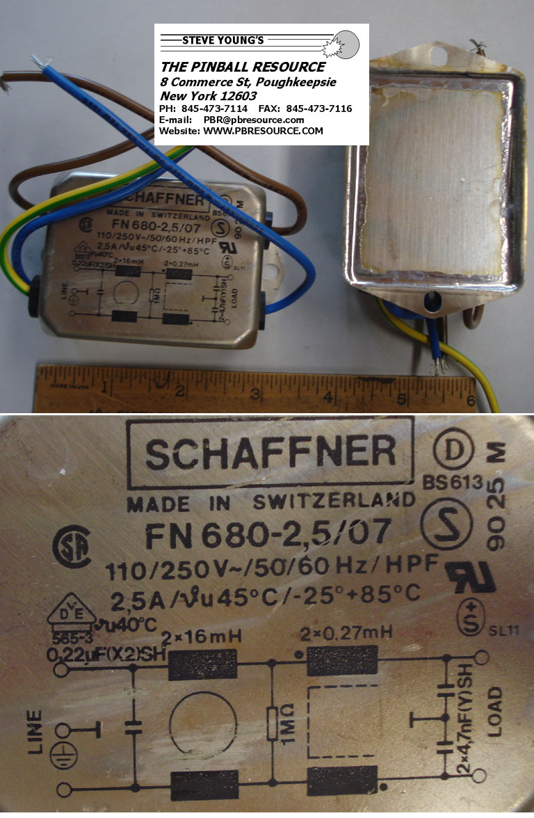
If you are still using the original game mains lead that is connected to the filter (on the side of the cab) then to the on/off switch there is a chance the filter is damaged.
On the LOAD side of the filter do you get the same as the LINE side?
From the filter the mains goes to the switch you are possibly having an issue with. Being careful at all times, making changes with the power off, you can jumper the switch terminals, from the switch the wires go to J2 pins 6 & 7. Here you can check the test points, with J1 and J3 unplugged IMO. Just confirm you have all the correct voltages on the rectifier board.
Are you unsure if all the wires going to the 3 plugs that connect to the headers are correct?
your TP5, is that a typo, should be at about 44VDC
TP2 is for your displays and too low.
I'm fine with you not doing it, but can you connect J2 only and check test points?
For wire colours, this should be close: https://www.ipdb.org/files/1580/Stern_1979_Meteor_Schematics.pdf
in post 152 TP is at 4.4 VDC which is your solenoid voltage. Doesn't matter, your readings at the Test Points are okay except TP 5 should be DC.
So J1 is your playfield, and your switched lamps.
Somewhere, at least one part of the power side is shorting to ground.
Ideally you'd have a 10A circuit breaker to save going through fuses: Circuit Breaker Overload Protector Switch Fuse 3A 4A 5A 6A 8A 10A 15A 20A 30&ex Ebay.
Solder a dead fuse across the spade terminals.
Follow where your switched illumination joins to the playfield and look for a lamp body touching something it shouldn't, and vice versa.
J1 pin7, looking to be Blue. It is the common for all your switched lamps, it's soldered to the bases of the switched lamp holders
ahhhh, the joys of pinball.
it's nice if there's a quick fix and everything is sorted.
personally the MOV and the line filter should be replaced along with an on/off switch, and maybe a new mains cable before proceeding.
then the transformer, check all voltages, then check all wiring. there shouldn't be any spare/leftover wires unless a hack was done, if so you need to undo this.
a pic of each of your rectifier connectors would help before proceeding, just one of each showing what wires you have going into what slots.
this is why i suggested connecting only J2 and then checking the test points, as mentioned you can't assume anything is okay with a pinball because of who you purchased it from or where it came from, unless maybe if it's a close mate.
i'm happy to stay out of this if you don't like my suggestions, but going ahead and connecting the 3 connectors lead to another problem that could have been avoided. It's slow and steady that wins the race.......unless you've got a fully blown twin turbo top fueler with nitrous?
Quoted from MarkAnderson:I found the issue. The transformer was originally set up for 115v. The 115v had lugs 1 and 3 connected and 9 and 11 connected. To change to 120 the 9 to 11 connection needed to be removed and 5 needed to be connected to 7. Also the yellow wire from the board needed to be removed from 5 and connected to 7 which I did not do. So I am completing that now.
all good, I suggested this in post #49 about half way down.
without mean to sound like a prick, I get how such a long post can be confusing, but you may have saved some time reading it thoroughly?
regarding the pics i was wanting, a misunderstanding, but maybe a blessing?
i was wanting to see your connectors with the wires going in, to ensure J1, J2 & J3 are correct, but looking at the last lot of pics, well there is some fine soldering and some less desirable.
i suggest you remove all the solder splash, this being ANY excess solder other than what is on the wires going in the holes on the board before connecting anything else.
some may flick off, but ideally you would use a flux infused solder wick to remove them, IMO.
as keen as you may be, soldering is one skill you cannot rush.
the brown residue leftover from soldering is the flux from the solder. This can be removed with IPA (isopropyl alcohol). A must have IMO. Add some on a cotton bud or a rag and it will wash the flux off the board leaving it like new.
if your connectors on your Split Second are wired the same as pics (thanks to @Quench) you should be fine to connect J2 for the time being as J2 has the mains coming in for the rectifier board, to the rectifier board and confirm all test points are within the expected range of voltages, remembering to take it easy and test for AC at TP4.
If you find your readings are off there is always the possibility your meter leads are at fault.
A simple test is to set your meter to the lowest ohms (resistance) setting and touch the probes together, which should result in an ideal zero ohms reading.
0.1-0.5 ohms IMO would be okay.
If you see say 5 ohms then IMO your leads need attention, the connection to the meter and/or the probes you are using. This resistance will result in false voltage readings as there will be a voltage drop due to the unwanted resistance.
and please tidy up the solder splashes, they can/may cause issues if not now but in the future.
guessing a misunderstanding for your readings in post #191 and resistance. I was just suggesting how to see if there were any issues with your test leads.
post #192 voltage readings look great.
with the machine off connect the plugs to J1 & J3 and hopefully she boots into attract mode.
if not and there is an issue, we'll tackle that next, otherwise enjoy playing your pin.
just to add, when turning her on, be at the ready with your fingers on the on/off switch.........if you hear a coil lock on be prepared to turn her off immediately
this sounds like a connection issue, also remember there is only one AC Test Point/circuit, being the General Illumination, TP4.
have you repined the connectors J1, J2 & J3?
if not I highly suggest investing in a quality crimper, a few hundred trifurcon pins to suit the connectors.
if your confident with it fine, or I can run you through how I do it which isn't for everyone.
crimping sucks and takes a long time but is worth it.
if you're not too skilled at soldering and don't have the correct tip on your soldering iron and some narrow solder you'll end up melting the insulation in the crimp pin
just a suggestion, put your boards back in, all your connectors back on and tell us what happens?
i wouldn't be too fussed with the low HV reading, wait and see if your game boots up, goes into attract mode and displays come on and then check test points 2 and 4 on the solenoid driver board.
to get your correct flash sequence then the LED go dull you only need J4 on the mpu connected.
you sound so close by your description that it sounds like J4 may need repining and or the header cleaned but ideally replaced.
i'm sorry but I can't help with the voltages.
i'd be checking the rear of the mpu board at all the headers for any dry joints, or if in doubt reflow them with solder.
you could also post 1 clear pic of each header
with only J4 connected is the LED flash sequence still erratic?
I believe I can see cracks in the solder around pins 1, 2, & 6.
I suggest reflowing the solder at the rear of J4.
Touch the solder with the tip of iron and you will see it change colour/melt, at this point just add a tiny amount of solder whilst drawing your soldering iron tip upwards on the pin, that's my suggestion.
the 43VDC comes in on J4 pin 15, you could test here with the meter set to higher than 43VDC and put the black probe to ground and red probe in the back of the J4 connector pin 15.
also you could check TP3 on the MPU, bottom left, for about 21-22VDC, same way, black probe to ground, red probe to test point.
hopefully your new mains filter will have a tiny hole in each of spade terminals for your Varistor to go into or it makes it trick soldering your mains and the varistor in place at the same time. Please post a pic when it arrives.
Regarding your 1/2 43 VDC reading at J4, do you mean pin 15 of J4 or Test 3 on the MPU?
It's odd having correct voltages then incorrect then this n' that.
Is your battery in your multi meter okay?
Are you able to test the resistance of your leads? You'll need a spare lead that can be a substitute for the one in test.
On the Weebly rec board I can clearly see it printed 6.4VAC, which is what you're getting.
Is pin 5 on J3 pushed all the way in, like is it locking or can you pull it out.....I ask coz I can see the crimp end.
Don't worry about the high voltage reading you are getting, it's fine.
please try this, meter set to 200VDC, red probe in back of J3 pin 15 (the grey wire) so the meter probe is touching the crimp end of the pin, and the black probe to the ground braid in your cabinet. What reading do you get?
now you need to get the mpu booting and going into attract mode, LED flash sequence then it going dull.
you need 3 voltages for this, 5VDC, 12VDC and 43VDC all coming in on J4, also ground and ideally a working mpu board.
J4 pin 15= 43VDC then TP1 = 21.5VDC
J4 pin 16 = 5VDC then TP5 = 5VDC
J4 pin 12 = 12VDC then TP2 = 12VDC
J4 pin 19 = Ground
Quoted from MarkAnderson:Connector on mpu board j4 Pin 15 gives me 44.1. I have been getting 43or more on that connector for a day or two. I need to chase down 5 and 12 and ground now as they seem to be missing.
I asked you to check at the connector purely because you weren't getting 21.5 at TP3 on the board.
The 43VDC gets split into 2 to give you that reading at TP3.
I thought you repined the connector at J4? I had a feeling you may have severed the wires leaving maybe a strand or two hence not getting correct reading on the test points on the mpu board, but at the pins that connect to the header J4.
okay, another thought.....with the game OFF, and J4 connector on the J4 header, using your multi meter on the lowest ohms setting, to be able to check for continuity, it doesn't matter which way around the probes are, I'd like you to now check for continuity but also looking at the resistance setting and check each pin from 1 at the top to 19 at the bottom to their respective points on the mpu.
you should have next to zero ohms resistance.
the following is a guide, yes some of the pins do connect to other components that will/should also give you zero ohms resistance, but try the following please.
pins 1 -10 go to a one side of a resistor, just to the right of the J4 header is a row of vertical resistors
pin 11 goes to U11 (bottom 40 pin PIA) pin 18
pin 12 goes to L1, your 12 VDC comes in here
pin 13 goes to R3
pin 14 KEY
pin 15 goes to R113, between the inductors on the left hand side, your 43VDC comes in here
pin 16 goes to L2
pin 17 goes to L2 soldered to pin 16 on rear. Your 5V comes in here
pin 18 & 19 go to ground
If you get more than 1 ohm in resistance from the rear of the connector then make a note and reply with your results please.
yes you're right no pin 9, now have my glasses on ;/
as your mpu did seem to work then not, I'm trying to work out why.
the problem, well one of them is no 21.5 VDC at TP3. If you have 43VDC at pin 15 in the connector, and continuity to the board, you need to find out why you not getting the correct TP3 reading.
can you look at the SeaWitch Schematic and work it out? https://www.ipdb.org/files/2089/Stern_1980_Seawitch_schematics.pdf
can you see J4 on the top left of the first page, and pin 15 at the top of the header on the schematic?
after R113 (2.2K) the trace goes to TP3, the schematics show TP1, but I believe this is an error.
Yes you can swap game ROMs if the jumpers on the board are correct for the ROMs.
i'm sure I read that you had it at the rear of the pin in the header.....?
if it's there and you have continuity to board it may be an intermittent issue and maybe the pin is broken?
Quoted from MarkAnderson:How do I locate the coil that is blowing fuse a2F4? I thought it was in the coin door but it doesn't not seem to be there. It is highly likely it is a flipper. I am not sure how to isolate the issue. I have suspected both left and right and there are two on each side.
on the bottom of the solenoid driver board are the transistors for all the coils except the flippers. The flippers work via the relay also on the board.
you could try using a jumper lead and briefly grounding the metal tab on each transistor which will activate a coil.
if the breaker or fuse blows trying this procedure then you know where to look.
You're currently viewing posts by Pinsider Rikoshay.
Click here to go back to viewing the entire thread.
Wanna join the discussion? Please sign in to reply to this topic.

Great to see you're enjoying Pinside! Did you know Pinside is able to run without any 3rd-party banners or ads, thanks to the support from our visitors? Please consider a donation to Pinside and get anext to your username to show for it! Or better yet, subscribe to Pinside+!

This page was printed from https://pinside.com/pinball/forum/topic/stern-split-second-no-flashes-playfield-gi-on-no-backbox-lighting?tu=Rikoshay and we tried optimising it for printing. Some page elements may have been deliberately hidden.
Scan the QR code on the left to jump to the URL this document was printed from.
 Buffalo, NY