(Topic ID: 58120)
Linked Games
 Space Station
Williams, 1987
Space Station
Williams, 1987
Topic Gallery
You're currently viewing posts by Pinsider ajfclark.
Click here to go back to viewing the entire thread.
Quoted from MustangPaul:Welcome to the club. Hope it's in good shape.
There's a few issues, but nothing unfixable so far. It's obviously had a bit of a life though.
Playfield is decent except that every triangular insert needs to be reseated and reglued. Most of the plastics are ok. The entrance on the right ramp is a bit iffy and might need to be replaced at some stage. There's some very small gaps at the 1, 2, 3 lights in the upper PF which line up with my eye line when playing but my wife can't see them.
Electronically, I need to sort out an issue with special #5 (left jet doesn't fire), the top left flasher's wire has come unseated from the molex plug, the back panel orange flashers aren't working (I haven't looked yet so that could just be the #1251 bulbs are blown), the right ramp switch has a loose wire (currently under the pf) but the switch doesn't click either so it might need to be swapped out. [edit: nope, it's a leaf switch. Resoldered the detached wire and it should be all good. ]
I have the original displays as well as the replacement. Trying to determine what the actual fault was that motivated the previous owner to swap them out. He said it just stopped working one day and his repair guy said to go with the replacement displays. The HV side of the PS had a blown 3/8amp fuse at F1. I don't have the correct replacement on hand so I'm waiting on that before I go any further.
I did look at the PS input voltages from the transformer seem high. The white wires from the transformer are 100vac, not 88vac. The test points on the PS board give +13v and -15v to the centre so +28v across the outside.
Quoted from MustangPaul:I can see the game is in good hands, you know what your doing. Is your ramp good, Freeplay40 makes new ones, I have a blue clear one.
At first glance things looked ok, but I'd seen the ramp rattle when the ball hit it 20171127_142605 (resized).jpg
It came off without removing the lower screws :-/ 20171127_143154 (resized).jpg
Switch was easy to fix at least:20171127_143257 (resized).jpg
The top exit is a little beat too? 20171127_143410 (resized).jpg
1 week later
Quoted from ChrisPINk25:2. All three bumpers are not working - Haven't started researching yet.
Quoted from ChrisPINk25:4. The kick out under the space station doesn't work - Multi-ball doesn't work as a result
On mine, contrary to page 69 of the manual, that's on the same fuse as the jet bumpers. Red/white power wire.
Could be the fuse, could be the drivers in the top right corner of the CPU board. From memory F3 on the Aux Driver Board. Is the fuse blown?
Before replacing the fuse I'd at least visually check all the transistors around Q77, Q79 and Q73.
Quoted from ChrisPINk25:3. The contact in the metal ball trail to the left lock position doesn't work
Does the switch click? Is is still attached under the playfield?
Quoted from ChrisPINk25:6. Playfield - Some of the inserts have pushed the mylar up very slightly in several spots. Questions: Can I fix this and leave the mylar on?
I'm in the same boat:
20171202_192824 (resized).jpg
From memory, Hairdryer, block, clamp and then reglue the insert from behind. I think it's covered in detail in vid's ultimate playfield restoration thread which I intend to reread before I have a go.
Quoted from ChrisPINk25:Thanks ajfclark The F3 fuse is blown. I inspected Q77, 79 and 73 and they look fine. In regards to the switch, it clicks when I push it with my finger. When I do that with the game going, it doesn't register.
Before replacing the 2 1/2 amp fuse in F3, is there anything else I should check?
Thanks!
The switch with the spoon doesn't register in the switch tests as it's a special solenoid switch. The scoring switch (which the yoke of the jet bumper hits when the jet fires) should.
I'd check that the jet bumper special switches (the ones with the spoons) are all open before I changed the fuse. It could well be that one locked on a bit too much and that's what popped the fuse.
Quoted from ChrisPINk25:Thanks ajfclark . What's the easiest way to check if they are open? Underneath? Turns out the relay on the habit trail to the left is working. Condition green is also working, just hard to see. Fuses are ordered. I didnt have a 2.5 amp on hand.
Eye ball or put meter across each under the playfield.
Retro Refurbs have mentioned that they are trying to organise licensing for Bally/Williams decals (https://www.aussiearcade.com/showthread.php/90625-Best-place-for-decals). I wonder if they'd do decals or stencils for Space Station.
Quoted from ChrisPINk25:Before replacing the 2 1/2 amp fuse in F3, is there anything else I should check?
I'd also check the manual... F1 and F3 are listed as 2 amp slow blow in mine and on the cabinet.
Quoted from Rondogg:There are a bunch of bad values in the manual and there is an Amendment to the manual here:
http://mirror2.ipdb.org/files/2261/Williams_1987_Space_Station_Operations_Manual_Amendments_and_Additions.pdf
Just FYI...
That is a good point. I went through a printed copy of the manual when I got the game and made those amendments, and my cabinet documentation has stickers over the fuses changed. F1 and F3 were not changed. That said, the manual only has the jets on that circuit protected by F3, but the machine has the right dock too, so there's some potential if the jets are active and the right dock fires at the same time (during multiball?) to possibly blow that fuse.
If they blow at 2 amp I wouldn't be too worried about using 2.5 amp - later games did in those positions (eg Taxi).
Quoted from ChrisPINk25:Thanks guys. Plan on using a 2.5 amp when my fuses arrive. New issue. Found a broken gate under my ramp. This gate keeps balls from going into the right dock. Replacement part not available. The F14 gate looks close. Has anyone used a different gate there? The second pic is all the gates that looked close. The first gate is the F14 gate.
I use calipers to measure the diameter of the wire then purchase appropriate SS TIG wire from my local welding supplier to make gates like this. Music wire from hobby shops also works. There should be a similar gate somewhere on the playfield to model from.
eg. on Radical, old busted non-locking gate that gouged the ball guide behind it:
20170401_213203 (resized).jpg
New hotness made from $2 piece of SS TIG welding rod:
20170401_220847 (resized).jpg
Quoted from Its_me_aj:Out of all the games I currently own, I think space station has been the hardest to letter on. It’s such a fun and challenging game!
Letter?
I'll have to wait until I've cleaned my machine up properly before I comment on how difficult it is. It doesn't seem too bad to me, but the left flipper was an FL-11629, not FL-11630, so that might've been an unfair advantage.
Quoted from ChrisPINk25:Solved! I installed the solenoid saver and found out it was the lower jet bumper blowing the fuse. Went in for a close inspection. DOH! Metal gate looking thing was jammed under the bumper and the close by post assembly. Removed that and fuses no longer blow! Yeah! Anyone know what this bracket could be use for? It is thicker than a regular ball bracket.
Could it have come loose from the USA lanes and rattled down? 2.4mm or so for wire ball guides vs 1.6mm for the gates.
Also, what's a solenoid saver?
If it's been stuck on the coil might've got too hot and the resistance might have dropped? Should be around 4.2 ohm I think, but worth checking against the other 2. I'd look at the switch gap too and the action and make sure it all looks similar to the other 2.
Quoted from Platypus:yes it looks like that is from the USA lanes. My game has four total one each side of the light bulbs
Two left folks: https://pinside.com/pinball/forum/topic/freeplay40-ramps/page/35#post-4121182
Super excited.
Quoted from kechlesurf:Thanks for the reply. Wanted to make sure it didnt have that feature.
As for the high-score feature, I have batteries in it and have gone through the setup to try to figure out how to make the high scores be saved but with no luck. It shows the factory set high scores but even when i beat those scores, it does not let me put in my initials and save high score.
Is Adjustment 13 "highest scores" set to on?
1 week later
Quoted from Jcouls29:So, my son and I (proudly so), got our first pinball machine, SPACE STATION!! We love it. There are a few small things that I haven't been able to figure out. I searched through here and didn't see anyone having the problem (but 4 years is a long time to read through).
For some reason, we will dock left (or right) and a new ball won't kick out to continue play. It'll go through its check and eventually kick the ball out of the dock. It will even say "Docked Left" but nothing happens. Is this a ROM issue? I couldn't really find any adjustments in the manual that supports this issue.
Any ideas? We get excited we docked, then BLAM! no ball... Simple answers to common questions: Yes we have enough balls, all the switches/solenoids are working, it's just occasionally (more often than not) when docking it won't give us another ball to play.
Thanks in advance folks!
Just to confirm the locks are working as expected, it might be worth starting a game with the glass off, lock a ball in the left and then tap switch #48 on the habitrail. If the ball kicks out, the game is seeing the lock fine. Likewise, if you lock a ball in the right lock and tap switch #46, it should eject the ball from the lock.
If it says "Docked" and the light on the playfield lights and the kick out all works, it's registering the ball in the lock fine. If it doesn't kick out another ball into the shooter lane, it already thinks another ball is in play. The machine keeps track of how many balls are in play by counting how many it can see in the locks and the trough. If it happens with both docks, it would be something common to both sets of logic. I'd check the trough switches first.
If it doesn't say docked, I'd check the column 6 switches.
On a different note unrelated the the previous post, does the top left roll under (switch #37) do anything? I've not been able to determine it having any effect on play.
They're probably a bit more of a bastard to get to. It is possible to pull the playfield forward a bit to make access easier back there, but I've never found a good way to prop the playfield while it's forward.
Maybe one of the other more experience members has a good method?
If A/C switching is working (and it sounds like it is), A side functions work but C side of a pair doesn't, I'd be looking at continuity of wiring first as there's not a great deal that's common to the C side but not the A side.
What about the flasher top left of the mini playfield? For me that flashes with the upper one you circled.
The top left blue flasher has black yellow and orange both daisy chain to the upper flasher you circled. The Orange continues down the playfield, via left dock coil, via left flashers, via relaunch flashers, then to the bottom right flasher with black orange ground. Both then Daisy chain to the upper right flasher you circled.
As the top left flasher and almost everything else on the orange works, the orange cable to the central flasher at least has continuity. The upper left blue and the central flasher are installed in parallel so I'd check the black yellow and make sure the orange hasn't come loose at either the top left connector or the socket. Check the orange is connected too.
As the upper right flasher is at the end of the chain I can't make any guesses about what is and isn't connected, but it's installed in parallel to the lower right flasher, so of that's working, wiring seems likely.
Thanks for posting by the way.
I hadn't noticed the upper of my right flashers wasn't working. Pulled the bulb, it checks OK with a meter. Check continuity to the lower right flasher and is ok on the tabs. The socket itself however wasn't electrically connected to the tab anymore. Rotated the socket a bit and it came good.
I'll put a dab of solder between the tab and the body of the socket to ensure continuity.
Quoted from GRUMPY:but they still need to use dropping resistors so that the voltage is not to high for the bulbs.
Seems weird that they put resistors in front of #89s for flashers, yet the 3 #1251s they didn't put a resistor in front of and use #89s? Would that be because the duty cycle would have been too high in that usage?
My understanding is there's a resistor in circuit with the #89s to drop the voltage and if you took the resistor out of the circuit, the #89s would blow, right?
I'm wondering why they didn't put a resistor in front of the orange panel lights and use #89s. With the duty cycle those lights have the resistors would generate a lot of heat? Or just that #1251 was cheaper than a resistor?
Also thinking about whether I could mod mine to use #89 LEDs instead of #1251 by adding a resistor in series with each of those 3 sockets.
Quoted from GRUMPY:Yes you can, but I would only do this for leds. If standard #89 bulbs were used I would not use the same amount of resistance for the dropping resistor as they were only intended to be flashed. You would need to at least double it and see what kind of temps you get on the dropping resistor while on.
Thanks for putting up with my spit balling.
What if the 3 sockets were rewired in series instead of parallel? I realise one bulb blowing would render all three out, but would that effectively drop the voltage to something an #89 could handle? Would heat dissipation still be an issue?
I notice those 3 sockets do not sit inside the domes - I assume because they got too hot or are 1251s just too big?
Quoted from MoSeS_1592:Who's question were you answering?
I assume this is the correct pairing:
Quoted from MoSeS_1592:This game looks really cool, it's been on my potential purchase list for a while now. I'm curious, does the attract mode on this game demonstrate the "green condition"?
Quoted from ChrisPINk25:Hey Guys. A couple of questions about the resistors on the light board. Can they be installed in either direction? Also, the manual says 3 ohm 5 watt 10%, but great plains only has 3 ohm 5 watt 5%. Will the great plains one work?
https://www.greatplainselectronics.com/proddetail.asp?prod=RC5W-3
Thanks, Chris K
They can go in either way as resistors aren't polarised. Mount them slightly off the board to allow air flow for cooling.
The tolerance % is the allowed difference from the marked resistance to the actual resistance. eg. A resistor marked 100 ohm 5% could actually be 95-105 ohm. If it was 10% it could measure anywhere between 90-110 ohm.
A tighter tolerance is fine, just slightly more expensive.
Quoted from Chosen_S:I used Krylon rattle cans (they have the absolute best spraying tip) , easy... red, blue, white, satin black. Looks amazing
Pics?
I haven't watched this yet, but Colorado Pinball streamed Space Station (or tried to and the internet crapped out so they uploaded it later): https://www.twitch.tv/videos/216829732
Quoted from Its_me_aj:Yeah we had issues with my internet crapping out right when we were starting the stream.
All good. I live in the land of expensive, crap internet so I totally understand.
Quoted from kechlesurf:Morning Everyone,
Machine has been working great since i was able to fix the space station motor and the issue with the balls not staying dock. But a new issue has popped up which shouldnt be to difficult to fix but of course, want to ask any advice from the experts before I tackle this issue (as it will be my first time doing it).
The right flipper is lame and very weak. On Monday, when I looked at it, I was able to get it working by making the right flipper button "switch" make better contact (apologies that I do not know what everything is called yet and the correct terminology). That fixed it and gave the flipper more power but was not as strong as the left flipper and right flipper button had to be hit right in the middle for it to work (couldn't hit the side of the button and get it to make contact).
But last night, the flipper was barely working and does not have enough power to hit the ball anywhere. So my first step is to clean the switch that i looked at yesterday but wanted to check what is the best way to clean these switches? I want to make sure I do not do more damage when I am trying to fix it.
I am guessing it is more than just the switch causing issues and probably going to order a new flipper kit and go that route to make sure I fix the problem and also to learn how to do flipper replacement since i have yet to do that.
Does anyone have any guidance, suggestions, or ideas?
There's a saying that a picture is worth 1000 words. When asking for help this is definitely true and gets around a lot of the problems with terminology. I'll try to find some.
First things first - does the flipper plunger move into the coil freely when you push it in by hand? Does it feel the same as the other flipper? If they feel different, it could be a mechanical issue, not and electrical one.
If it's electrical...
There's two switches for each flipper. The cabinet switch, and the End of Stroke (EOS) switch on each flipper. If either of these is burned, pitted, not making contact, etc your flipper will be weak.
Cabinet switch:
The cabinet switch is easy to check as you can see it when you've lifted the playfield.
- Are the screws tight?
- Is the capacitor (usually brown disk) still attached to the switch?
- When you press the button do the contacts meet before the button is all the way in? The contacts should rub together slightly when the button is fully pressed. If they don't, carefully bend the shorter arm of the switch closer. If you're adjusting the switch, use an adjustment tool close to the switch stack (either a proper tool or the blade blade screwdriver).
- Are the contacts really burnt and pitted? If they are, you can try burnishing or sanding them as they are high voltage contacts (never file low voltage ones). It's often better to replace them if they are burnt.
- If you have a multimeter, it's useful to measure the resistance across the switch when it's closed. It should be really low. If it's not, it's sapping power.
- Is the plastic button firmly attached to the cabinet, not broken, etc (check against the other button)
Here's my flippers which work, but could use rebuild:
left right
EOS switch:
The EOS is located on the flippers. There's two switches on each flipper. The switch closest to the coil and directly connected to the coil is the EOS switch. This is a high voltage switch. The second switch which is stacked with the triangular nylon spacer is the lane change switch. It is low switch connected to the switch matrix. Do not allow these to short together or the switch matrix won't work any more.
- The EOS switch is on the flipper and should only be open when the flipper is fully plunged and it should be closed the rest of the time.
- When you press the flipper plunger in do the contacts open just before the plunger is all the way in? The contacts should rub together slightly when the switch closes. If they don't, carefully adjust the switch. If you're adjusting the switch, use an adjustment tool close to the switch stack (either a proper tool or the blade blade screwdriver).
- You should see the sliding of the contacts past each other as the switch is opened and closed.
- Are the contacts really burnt and pitted? If they are, you can try filing or sanding them as they are high voltage contacts (never file low voltage ones). It's often better to replace them if they are really burnt.
- If you have a multimeter, it's useful to measure the resistance across the switch when it's closed. It should be really low. If it's not, it's sapping power.
Quoted from Its_me_aj:Does anyone have any custom apron cards?
I like these, but I don't remember where I found them... Somewhere in this thread probably:
instruction-cards.jpg
[edit: I use the thread gallery function to hunt for things like this: https://pinside.com/pinball/forum/topic/space-station-club-members-only?gallery
The cards above came from this post from Chosen_S https://pinside.com/pinball/forum/topic/space-station-club-members-only/page/11#post-2427031
There's more from goingincirclez here: https://pinside.com/pinball/forum/topic/space-station-club-members-only/page/22#post-3086556 ]
Quoted from MustangPaul:It may be old and dried out, replace wit a new one and see how long it lasts. Can't tell from the picture if it's bent, take it out and check it out. The one behind it looks bad too.
Quoted from MustangPaul:From the looks of the first picture that's an original 30 year old rubber. Change it out and your good for another 30 years. Probably the whole game need to be re-rubbered.
Sorry, got a call while I was adding that post and forgot to add the text.
The ring sits against the post and there's a fair bit of front to back play in it so I guess every time the ball hits the top side of it the ring jams down that rubber. Weirdly the balls eye view on ipdb has a wide rubber on that post (http://www.ipdb.org/showpic.pl?id=2261&picno=9154&zoom=1) which would surely get chewed out? Dave Santoto's page has a good shot of the post with a sleeve on it, but the ring seems to be chewing that out too: http://spacestation.santoro.com/files/2012/10/P1020885.jpg
pasted_image (resized).png
Hopefully something like Cliffy sleeves will stay out of the way of that ring? Maybe a different post would work better there?
I do plan to change out all the rubbers. The whole thing will be stripped at some stage in the next few months as I'd really like to try to level all the inserts. It's hard to see ![]() , but a few are a bit above the surface:
, but a few are a bit above the surface:
pasted_image (resized).png
When I've got it all apart, I'll make a list, check it twice and then order a bunch of stuff.
Quoted from waveman:Thanks for posting this! I had the exact same problem after replacing the rubber sleeve and was wondering if something's wrong or if maybe there shouldn't be a rubber sleeve on that post at all.
Good to know that this is a more common issue. Maybe the post is just a tad too close to the pop bumper? I recently replace the rubber sleeve with one that is a bit narrower, hoping it will avoid the issue (don't know yet if that worked).
I'm wondering if a different post style might work better. For instance, Radical uses this and the ring never seems to hit the rubber (though perhaps it's just further away):
20180113_062714 (resized).jpg
1 week later
Quoted from TicTacSeth:Hey guys, need some help. I’m replacing the IDC connector that runs the lights behind the back glass. I clipped the wires, but two of them are so burned I can’t tell which order they are in. Can someone take a pic for me? It’s the board on the inside left wall of the back box, the 4 pin IDC on the top left.
They are wired straight through so as long as both 4 pins connectors at the top match, it'd work.
Mine are:
1 brown
2 white brown
3 green
4 white green
Quoted from TicTacSeth:I’m back in action, thanks ajfclark!
Most welcome. Do you know what switch 37/top left roll under does? I can't figure it out.
Quoted from TicTacSeth:On start up I get adjust switch for 50. 52 and 53. Started since putting in the new blue ramp.
As for the lane change switches, no idea what’s wrong there. They worked when I was looking at buying it, didn’t work when I got it home. High scores are all blank names sadly because of that.
pasted_image (resized).png
I think you are missing a whole column - 7. I'll just go have a look and double check how that is wired.
Given you are missing the whole column it might be something as simple as a disconnected wire - especially since it happened since moving the machine. The column 7 switches all connect to a green wire with violet. I'd start by looking at the MPU board. 1J8 is the switch columns. Pin 8 (counting right to left, pin 1 is marked on the right) should have a green/violet wire attached:
pasted_image (resized).png
If it doesn't have a wire there, that's your problem.
If it looks ok, with the power off, reseating the connector may help.
If there is a wire there, and reseating the connector didn't help, it's probably worth testing the MPU board. With the power off, disconnect 1J8 and 1J10. Get a diode and an alligator lead. Clip one end of the alligator to the problem column (1J8-8) and the other to the banded end of the diode. Power up, go in to switch edges and tap the unbanded end of the diode to the pins of 1J10. You should see switch closures register.
pasted_image (resized).png
If you don't see switch closures, the problem is in the MPU board. Hopefully not.
If the MPU is ok, the issue is either the connector itself or in the playfield.
If you're hunting for a issue in the wiring, the green/violet heads from the connector housing to the back left corner, towards the flippers, then loops back up the right side of the playfield. There should be two green/violet wires attached to the lane change switch on the right flipper (56). There's also a jumper from that to the left flipper's lane change switch (55) - on my machine it's yellow. From the right flipper the wire goes to the lower 10 point contact (54), then the upper 10 point contact (50) and then to a molex plug that heads up to through the playfield to the space station board with opto switches 52 and 53.
I would use my multimeter to trace that continuity and go from there.
Quoted from TicTacSeth:Ok, looking at it now, wire is there. Repeating meaning reflow solder? Or just pull it and put it back?
Yeah, just unplug it and replug it.
Quoted from TicTacSeth:I don’t have a diode, but I did just purchase a DMM. Should I go right to that step? Also, I just bought the DMM last week, I need to learn how to check continuity
Sure you could.
Quoted from TicTacSeth:Ok, so I’ve checked continuity for each segment starting from the back box. It checked out, then checked from the back box to the idc at the optos board, and heard the sweet sound of continuity there too. (I guess I should have started with that. Ha!)
Not sure if this is odd , but before putting the space station section back on, I turned on the machine and the switch errors didn’t immediately pop up, though the credit dot was still there. Checked this multiple times. So tried to play it to see if Lane changes would work, but they still didn’t. So put the space station lanes and toy back on, then sure enough when I turned it on again the switch errors were back.
So back to continuity, does this mean it’s a board problem?
The opto board is at the very far end of the cable from the backbox. I would expect the lane change switches and everything else to register regardless of what the opto board was up to.
The game will run without the opto board connected, if you unplug 6 pin connector underneath the playfield at the back right. the game will power on fine - the space station will spin a little longer than usual until it figures out the board isn't there.
Actually, that's a good question, how long does your space station spin for at power up? 1-2 seconds or a good deal longer than that? I'd guess longer, because that's what it does when the space station opto switches aren't closing.
I'm starting to think it's an MPU problem though (Q42 and friends) and perhaps it might be better to get someone like GRUMPY to take a look?
Quoted from vwallat99:Can someone here help me , I'm trying to figure out what switch is needed for the right slingshot? I need a new one currently and can't seem to find it online.
The scoring switch or the activation? Both are listed on page 50 of the manual. #63 and #64 are the scoring switches sw-1a-122. The activation switches are listed in the note at the bottom of the page as A-48340H/B-8734 w/RC.
Neither seem to be readily available from my quick look around.
Quoted from TicTacSeth:Yeah, I definitely know the Opto is an issue. But it’s on the same column right? The space station spends quite a bit and it doesn’t always line up correctly. I have already replaced the motor , And that only fixed the fact that I would try to turn the opposite way for a split second before turning the correct way. So I guess I have an extra motor, that might still be good. But I think the Opto board shouldn’t affect the lane change switches and others correct?
Correct, the opto board shouldn't affect the other switches. The station spins and doesn't line up because the optos aren't reporting the position back to the MPU or they are an the MPU can't 'hear' it. Given that the whole column is missing, I suspect the latter. It's probably worth checking the integrity of the EOS switches, the nylon separators, etc and making sure there's no way the EOS switch or wiring can touch the switch matrix switch. I know bad things can happen if they ever touch as the switch matrix doesn't like getting 50v.
Missing a whole column is not something I've had to debug before but I'm happy to muddle along a bit if you are. The relevant part of the MPU schematic is the top left corner of the 75 page of the pdf on ipdb:
pasted_image (resized).png
The Switch Matrix Drives on the left are the columns. ST(robe)7 is column 7, 1J8-8 - Q42 - Pin 12 U40.
First thing I'd do is check continuity from useful point through the IDC connector, say the collector of Q42 through to the green/violet wire on the playfield. It'd be awesome if it was that simple.
I'd do a visual check on that area of the board too.
I'd look at the voltage that point with a DMM (or a logic probe if you've got one) and see if it's pulsing the same and the similar point on a working column's transistor like Q47. Likewise pin 12 of U40 vs say pin 7.
Quoted from TicTacSeth:I think I understood about half of that haha. I have a DMM, how do I check the voltage?
I see Q42 and it looks like the round part of it is problem off. Could it be that?
No need to check voltages as the visual test shows that Q42 is FUBAR. It needs to be replaced (and potentially other components in the path), but as grumpy suggests before it's replaced you need to ensure there's no connectivity between the high voltage and the switch matrix.
The lane change switches on the flippers are the most likely candidate. The EOS switch should be electrically isolated from the lane change switch. Check that the nylon spacer is intact. Check that the tabs of the switches haven't been bent. Check with a meter that there's no connectivity between the two switches for the whole range of motion of the flippers. Etc
Quoted from TicTacSeth:Feels like progress! I must be getting close, thanks for helping me diagnose AJ and Grumpy.
For checking flipper vs switches, how do I read that voltage-wise?
I'd just be looking for a lack of continuity. There should be no connection between the EOS switch and the lane change switches. The fault suggests that at some stage there was.
Quoted from TicTacSeth:Ah, so more just ensure they aren’t touching?
I'd use my eyes too, but I'd rely on a meter measuring continuity or resistance more. There might be a path between them that's not obvious visually. eg through the base plate or something. Hopefully it's something really obvious like the nylon triangle spacer is missing or that the tabs between the outer leaf of the EOS and the inner leaf of the lane change switch are too close. The spacer should look something like this:
pasted_image (resized).png
Quoted from TicTacSeth:I need to start looking into what it takes to replace a Q42
If soldering isn't your thing, I'd find something to practise on first.
Quoted from TicTacSeth:Cool, I’ve soldered the IDC connectors before, assuming with smaller pieces it’s a bit tougher.
If I know the part is fried, I usually:
- cut the legs close to the body of the part
- desolder the remaining leg parts
- clean up with solder sucker
- fit new part and solder
Quoted from TicTacSeth:Also, there are three transistors on Marco Specialties that look the same or similar. How do I know which one to match it up?
The parts breakdown of the System 11b MPU on page 38 of the manual lists Q1, Q40, Q42-Q49 and Transistor, NPN, 2N3904, TO-92.
This agrees with the schematic above which notes the transistors are 2N3904.
So this one: http://www.marcospecialties.com/pinball-parts/2N3904
I wouldn't order them from Marco, but that's partially because I'm on the other side of the world. I'd use a regular electronics supplier like rs-online as they are cheaper (but you often have to order a bunch): https://au.rs-online.com/web/p/bipolar-transistors/7390442/
Quoted from heni1977:Lots of learning kits on line. I bought a lot of those little radio shack toys and gave them to the kid and fam after I was done with them. Actually building the radio one is really rewarding!
Yup. I started desoldering old boards for my grandpa in the holidays. My first assembly projects were little Dick Smith funways projects. Wireless fm microphones, electronic dice, etc.
Quoted from vwallat99:Activation. Well that sucks for me..
Quoted from Rondogg:Use a WPC flipper spring instead of that conical spring that comes with the kit:
https://pinside.com/pinball/forum/topic/system-11-to-wpc#post-1798005
Rather than adding a screw into the playfield, I drill a small hole in the flipper bracket as per vid1900 's thread: https://pinside.com/pinball/forum/topic/vids-guide-to-upgradingrebuilding-flippers#post-284661
Trivial to do, looks better and makes the spring pull in the same plane as the flipper plunger.
I'll answer the second question first.
Quoted from TicTacSeth:It also looks different than the two beside it, was it the wrong part?
It looks like it's previously kamikazed itself and then replaced.
Quoted from TicTacSeth:Hey ajfclark, I just pulled off the board to replace Q42, when I saw this up on Q77. Can’t be good. What does this control?
If you look at the second page of the manual, there's a list of solenoids and which transistors are their drivers:
Space Station Solenoid Table (resized).png
Q77 is a special solenoid #5, the left jet bumper. Special Solenoids are a bit special, in both complementary and derogatory senses of the word. They can be controlled by the CPU, and they are also controlled by a direct switch that comes in through 1J18. Because there's a single fuse for multiple coils that might fire almost at the same time (eg all the jets) if a single switch gets stuck on, the coil, driver, etc are all candidates to burn. It's enough of a problem that people sometimes add individual fuses for the special solenoids and this guy made a nice board to hold them that I keep meaning to buy: http://nvram.weebly.com/repair--conversion-kits.html
Why was it designed that way? I guess the original intent was that things that needed super snappy response would be Specials. As there's a direct switch, the coil is activated without waiting for the CPU to see the switch is close and fire the coil. Later, they realised the delay of a switch hit to the CPU triggering the coil wasn't long enough to outweigh the problems and through the System 11B machines the use of 1J18 was phased out. Special solenoids still exist in System 11C boards, but the switches to 1J18 are never connected. If you hold down a switch on a System 11C special, the coil fires once and then the CPU ignores it.
My #5 was cooked when I got my #space station so I wonder if it's a common fault with the way the playfield is setup - perhaps that post rubber that gets chewed out eventually holds the switch down.
Quoted from TicTacSeth:New transistor is in on Q42 and I’m back in full action for the first time! The credit dot is still there, but hey, The station lines up every time and condition green’s galore are about to happen! Thanks ajfclark for all the help!
Go through the switch test, tap every switch in the column to test. I think that'll make the dot go away.
Quoted from TicTacSeth:Credit dot gone! Thanks again! This game is so different when you can plan for Condition greens and up the scoring through completing the 1,2,3 and U,S,A roll overs. I also feel spoiled now that the station lines up perfectly and even directs the ball to the lock you need if you hit the left orbit. Lol
I thought beating my high score would be easy, and that I’d get it done in my first try last night, but looks like it will take more work to top the 4.6mm I got when none of this stuff worked. Haha. Here’s to pursuing greatness!
I'd clear the high scores.
A) it'll be a different game now
B) with no lane change you couldn't have put your initials in anyway
C) any excuse to hear that tune and get the light show
1 week later
Quoted from scarybeard:sounds like there might be at least a handful of interested people. I'll see if I can play around with a design. goingincirclez I like the idea of using traditional lane dividers! I'll have to look up measurements.
I think the toughest bit to deal with will be where the shooter ramp and the kicker join up with the upper playfield. I'll probably have to cut negative shapes to allow those lanes to be 'flush' with the playfield, and add a 2nd layer below it to secure the ramps to.
I'll draw up some ideas.
Doesn't need to be flush does it? The ball immediately enters a gate so it can't come back and hit the ends of the wireform.
Having a quick look at mine, the wireform sits proud of the surface of the upper playfield.
I wonder how it would perform without the curved section of the front wall. The ball should fall in the hole anyway most of the time, shouldn't it?
Could the back wall be a second flat piece sitting in the same plane as the other two and the ball just rolls along the edge of it? Wouldn't look the same as the original, but wouldn't need curving? Kind of like the ball guides near the flippers. You could use standard post and separators to connect the pieces.
Quoted from scarybeard:yea we could probably get away with not curving the back wall but would require a post with rubber ring 'behind' the main ramp gate. When the kicker on the right shoots up the ball it currently is curved to the Gate and bounces back. If that wall were straight we would need to put a post and rubber there for it to bounce off of, because were making negative space.
I mean rather than having the vertical piece you have for the back wall, cut another the same as the top flat piece, stack them with spacers and attach to the bottom piece (potentially by extending the bottom piece all the way to the back).
The curve of the wall is then the edge of the middle piece rather than a flat piece you have to flex into shape. Like the metal slice in the flipper lane guides.
Quoted from scarybeard:Yea I think we’re on the same page. These could look super cool with light passing through em...
They would.
But I mean at the back, where the flasher is. ![]()
So I noticed that I don't have this post behind the left standup target:
pasted_image (resized).png
I do have a hole into the playfield:
pasted_image (resized).png
There's no tee-nut. It looks like a nut would clash with the light socket for the green GI bulb:
pasted_image (resized).png
Does anyone have a part number for the part that fits here? A picture of the underside would be great too.
Quick question. I'm about to try getting the HV displays back up and running.I'm not 100% sure of the value of the two fuses in the middle of the backbox which is the HV power to the display. The manual says 1/10 amp slow blow. The stickers in the backbox say 1/10 amp but don't specify fast or slow whereas all the others explicit say slow blow:
20180215_181434 (resized).jpg
Should it be fast or slow?
Quoted from GRUMPY:Slow.
Thanks @grumpy. I was guessing they ran out of space on the labels.
So.... The slow blow fuses... didn't. The power supply fuse went first. ![]() That's not the way that should work is it?
That's not the way that should work is it?
https://pinside.com/pinball/forum/topic/testing-williams-hv-display-board#post-4232780
Quoted from MustangPaul:What color and material you making it out of?
I'm hoping for a light blue to match the super awesome ramps Freeplay40 makes... but my upper playfield is still intact, so I guess my vote doesn't mean much.
Would be good if it was transparent enough to see the USA lights without hunching down though.
Quoted from sly:I there!
Need help with the lamps on the GI that are very weak ...
On the power supplie board test point:
Board=5765-09466-0
TpTp1=5 vdc
Tp3=11.6vdc
Tp4= -14vdc
Tp1=10.1 vac
Tp3=24.9vac
Tp4=0vac
Any clue???
None of the test points are on the GI circuits. You need to look at the 6v AC feed which goes from the transformer in to the bottom right corner of the power supply board via 2 yellow and 2 yellow white wires, that feeds straight out of 3J8 to the 4 fuses on the right side of the backbox. All the connectors on the GI circuits have the habit of cooking themselves, both the two on the power supply board and those on the interconnect boards and the GI relay boards. The GI relay boards also have a habit of cracking their solder joints.
Are you having issues with one particular strand or just various sockets on in various places?
Quoted from scarybeard:Test fit the cardboard proxy today. Mostly fit. A few adjustments to be made and I think I’ll be ready for an acrylic proxy.
Nice work! The only downside I can see of the layered back section is that the bulbs might be awkwardly exposed?
Quoted from ChrisPINk25:Woo Hoo! Finally got my Space Station up and running again today after tear down. I didn't go as hard core as some. Rebuilt the pops, flippers, cleaned, added new rubbers, Leds and a playfield protector. I chose to leave the mylar on.
After about an hour of playing, hit 3.5MM! I recorded the high score song (initials times out, so it is blank).
» YouTube video
Count me in for a new mini playfield when it happens.
Chris
I do that too... ![]()
Quoted from kechlesurf:Great point. I took a picture before i replaced the coil and put it together just like the picture. This is something i will remember, once i get it right, i will make sure not to make the sames mistakes again.
I would recommend understanding how the primary power winding and secondary hold winding work and then where the EOS switch and capacitor wires go will make perfect sense.
If you look at the diagram on top of the coil:
pasted_image (resized).png
Power comes in on terminal 3. So where does the ground go? If we attach the ground to 2, the primary winding will always be used. That's not what we want so ground must be terminal 1.
At this stage, with no EOS attached, electricity will only flow from 3 to 1 via the secondary. The idea of the EOS is that when it is closed the electricity should travel through the primary winding and when it is open, the power should travel through the secondary winding.
There's 3 possible places you could attach the EOS:
3+1 : Power will flow directly from +50v to the EOS and then ground, blowing the fuse
3+2 : Power can only reach ground via the secondary coil
2+1 : Power will flow through the primary then the EOS to ground when the EOS is closed, and via the secondary when the EOS is open.
The capacitor is to protect the EOS, not the coil, and is always directly attached to the EOS.
If your coil doesn't have a diagram on the top, the terminals with fat wires are the ends of the primary winding and the terminals with the thin wires are the ends of the secondary winding.
1 week later
I have a related question. I find sometimes my machine doesn't pay the Stop and Go award. It also seems to turn the Space Station more than is needed. eg. I hit the left VUK, it kicks the ball, then turns the station, then realised it's lined the right ramp up to the now occupied dock and turns the station again.
I assume these two things mean that the optos either aren;t always lined up right, or the interrupter is possibly borked?
Quoted from Drickey86:Looking for a correct apron anyone have one to sell turns out mine doesnt have the outlane kicker hole.so ready to play this thing !
I know a guy in Europe that's got one. PM me if you want details.
Speaking of kickbacks, the manual says 24-900, but it always seems to be a 23-800 which would be slightly stronger. Thoughts?
Quoted from Drickey86:Just about finished with my restoration aside form one part. I need to find the space station diverter opto cam that drives the ball diverter mine is completely missing. (Black part pictured on top of opto board) hope someone has one or knows where i can get one .
Candidate for a 3d printed copy?
Quoted from Drickey86:Tyring to sort out some hack jobs on witing and fix the the right way could someone post a pic of connector j1 and connector j8 on the power supply board i want to be sure i have all wires in the correct places thanks also is there any reason i couldnt use a bally style conncetor and pins on j8 as i do not have the correct .156 idc in my parts stock but do have .156 trifuricon
Does the power wiring diagram at the back of the manual have the required information?
Quoted from Drickey86:I have a printed out version and its not the best and too small to see
1 week later
Quoted from Kallek:Other question. I've seen that the original plunger/shooter spring (original part.nr: 10-148-5) is really a rare item and i cant find it anywhere. Now i have a standard black one and it´s really weak. I also suspect the original spring is a little taller/shorter or something cause the plunger doesent reach the ball really well.
Is there a good alternative to the original spring or could someone point me to a place that might have them in stock?
Thanks a bunch for the help so far!
Give it a bit of a stretch.
Quoted from Chosen_S:I posted some a while back, they were the perfect size, all you hav to do was print them out ... I want to say 6”x3.25”, but that may need to be checked
My memory says 152mm x 82mm which is 5.98" x 3.23".
Quoted from Kallek:6. The bottom right numeric display does not work. Guess i have to replace the whole thing with an Xpin? Is there anything else i can test before i spend $200+ on a whole new display unit?
UPDATE tried the +100v -100V at the power supply. Did'nt get the -100v at all then i blew the 0.25A fuse so i guess i have to order some of theese too.UPDATE: well, I think I f-cked up the PSU-board, possibly shorted something. Now it blows the 0.25a fuse after replacing it. Disconnected the wording going to the displays but. I luck, still blows fuses. Between the 0.25A fuse I get a read of about 100v, is it suppose to be that high or is there something wrong with the board/transistor or other? Ordered a dis200 display but haven’t received it yet.
If the 1/4 amp fuse on the PSU is now blowing, yes, it's likely that one of the transistors has shorted or there's some other issue in the high voltage side of things. You can rebuild it, but if you have an xpin display coming, don't stress about it as the xpin doesn't need the high voltage side of the PSU. Leave the F1 fuse on the PSU empty, take out the two in the centre of the back box (1/10 amp), and sell the remains of your high voltage displays on to help subsidise the cost of the xpin.
I've gone the other way and rebuilt the HV side of the PSU, but I still have issues with my HV display board itself. Even once I've fixed that I'm pretty sure I've only got 2 or 3 working displays. Comparatively it's a lot of work to get the HV displays working, and they eventually stop working anyway.
Quoted from Kallek:8. Open box switch seems to not work at all
What's the open box switch?
Quoted from Kallek:But where do I get the the power to the new display then? Isn’t it the same connector that blew the fuse? Or is there another one?
Ah, maybe I’ll try to sell the whole display unit as one piece, thanks for the tip!
The 6 pin power connector to the left display board carries:
1 -100vdc
2 Not connected
3 +100vdc
4 key
5 ground
6 +5vdc
The fuses in the backbox are directly inline with pins 1 and 3. As the LED board only needs the +5vdc connection, it's safe to leave those fuses out.
Quoted from Kallek:The coin box.
You mean the switch on the top left corner of the coin door? That's the memory protect switch mentioned on page 2 of the manual:
The memory protect switch is on the inside frame of the coin door. This interlock switch mst be open to clear bookkeeping totals, and to make game adjustments. It automatically opens, when the coin door opens.
It doesn't matter if it's broken. One of my system 11 machines it's completely missing:
pasted_image (resized).png
The black/red and white never connect anymore, so the memory is never protected.
Quoted from zFabi:Hey everyone,
Quick question what could lead to the kickback not working?
I replaced both Transistors still nothing...
Wiring has proper connection and the coil measures fine.
Does the switch register in the switch test?
Does the coil fire in the coil test?
Quoted from zFabi:It does register but doesn't fire I'll change the coil and drivers again and look if that solves it
If you have voltage at the coil, I'd check continuity from the coil back to the connector at the MPU.
Quoted from dinkydave46:Hi. Does anyone know where I can get custom cards for my space station I have just picked up?
Dave
Yup, two pages back. ![]()
I'll find them. Hang two.
[edit: actually it was 7 pages: https://pinside.com/pinball/forum/topic/space-station-club-members-only/page/41#post-4171043 ]
1 month later
Quoted from GRUMPY:Problem 1 and 2 are related to the same problem.
Here is a pic from an earlier post that will help.
https://images.pinside.com/c/be/cbe9599619727ddd3e449553bf184a443aea4d79/resized/large/cbe9599619727ddd3e449553bf184a443aea4d79.jpeg
That interconnect board has two wires cut on the top connector already:
Quoted from GRUMPY:I know, but I don't have a Space Station to get a good pic from. It was the best I could come up with on my lunch break.
Tell me what you need and I'll take as many pictures as you want @grumpy. You've been a huge help to me so it'd be nice to return the favour.
Quoted from uncle_jose:While checking for blown fuses and hacked jobs I found the following wires dangling (photo attached) any idea of where these go? (Slingshots are not working and I'm not sure if these are related to the missing connector from the picture I posted before.
Purple/yellow with brown/green go through a hole to the topside of the playfield, to the kickback coil on the left outlane:
pasted_image (resized).png
Quoted from uncle_jose:Also, can someone please post a photo of the setup at the light board? Mine is also attached.
Many thanks!
You can also fix just the two pins that burnt like someone did with mine:
pasted_image (resized).png
3 weeks later
Quoted from Its_me_aj:Took space station to the Rocky Mountain Showdown this last weekend. It played like a champ all weekend and everyone seemed to enjoy it. We also had a chance to play a game on it with Barry Ousler himself!! It completely made the whole weekend worth it!
That's really cool. Did you ask him what the switch on the left orbit does (or was supposed to do)?
Not sure if this has been mentioned before in here. Episode 36 of TOP Cast (http://www.pinrepair.com/topcast/past.php) is an interview with Barry. There's not a huge amount on Space Station, but there's a little:
TOPcast Show 35 - entire show (MP3 audio, 26meg, 75mins).
Sunday night show 5/20/07. Special guest Barry Oursler, Williams game designers from 1978 to 1996. Barry designed 35 games including Gorgar, Joust, Space Shuttle, Space Station, Comet, Pinbot, Fire, Space Station, Cyclone, Bad Cats, Harley Davidson, Dr.Who, BS Dracula, Dirty Harry, Junkyard, and many others. Barry sold over 135,000 pinball games of his design for Williams during his tenure.
http://www.pinrepair.com/topcast/showget.php?id=35
Almost wonder if it's worth making a thread for the TopCast episode and then linking all the games to it.
Quoted from midcoastsurf:Thanks for sharing!
- 2 of my relays are buzzing like crazy - the lower right (below power supply board) and one on the back of the backbox light board (upper right)
The board under the Power Supply is the Auxiliary Power Driver Board:pasted_image (resized).png
It's home to the A/C select relay.
The smaller board on the insert is a GI relay board that controls the flashing of the insert GI:
pasted_image (resized).png
Do they work?
The A/C relay selects between the A and C solenoid banks:
pasted_image (resized).png
Symptoms of malfunction would be one column or the other not working (and the other side firing in its place).
To make life easier, use the diagnostic modes. Here's a video I made going through the display test:
Do that, have a look at what the display does. While you're in there, run the coil test and see what each coil does.
I'm going to guess that the battery damage is most of the issue though.
Quoted from scarybeard:man... I wish I had waited and gotten the blue display. Everyone was sold out when I was shopping for one.
I'm still trying to rebuild the HV display as the missing segment on this one shit me to tears even though it's only visible twice in the whole game.
Quoted from midcoastsurf:Nice video ajfclark! I agree, that blue display looks sharp. Is that a Pinscore display, XPin, or other? I’ll post back once I can dig in a bit.
It does. It's a Rottendog. I have a few queries around the quality though. That segment went out within 6 months of it being made, but they haven't answered any of my emails asking for support. The screw tighten down onto tracks on one edge because they didn't leave enough clearance and none of the legs on the LEDs are trimmed off:
pasted_image (resized).png
Quoted from ozuba:Here ya’ go...got on the board, not sure if it’s a respectable score or not.
Getting there. I got 7something at one stage, but I found someone had put an fl-11629 on the left flipper instead of a 11630 so the right ramp was a doddle to hit. Since replacing the flipper coil with the correct one, my best is 6.6m.
Just reminded me that I need to update my score on here... https://pinside.com/pinball/archive/space-station/scores
Quoted from goingincirclez:You can then put the game into test mode, go into the "switch test", and see which switches are stuck. If the pop bumper switch shows up in test, investigate further.
This is not the case with Space Station, one of the last machines in the System 11s to use the Special Solenoid Activation Switches. The switch test only tests the scoring switch on the Special Solenoids - pop bumpers and the slingshots. It does not tell you if the activation switches are stuck.
If you look at the pop bumpers you'll see there's two switches. The spoon is the activation switch which has a resistor and capacitor across it as an RC debounce. When the pop fires, the fibre yoke will close a second switch - this is the scoring switch in the switch matrix.
There's a similar arrangement with the slingshots - the switches on the playfield are directly connected to the MPU and there's a second switch activated by the mechanism itself in the switch matrix.
Special solenoids switches connect to the MPU via 1J18 (the first vertical connector at the top right of the MPU board with mostly orange wires):
pasted_image (resized).png
If you disconnect that, go in to test mode or game mode and the pop bumper fires, you have an MPU board issue.
If you disconnect that, go in to test mode or game mode and the pop bumper doesn't fire, you have a short in the activation switch's wiring.
Quoted from jedi42:Hi guys,
Working on a SS for what it seems like forever. The board that came with it had battery corrosion, and I just couldn't get it to work consistently so I found a used board with no corrosion. It boots fine and plays a game fine, all is good except for some lighting issues.
For columns 5, 6, 7 & 8 of the lamp matrix, each light in the 4 columns light at the same time for each respective row. See the colour coded sheet I made. For each colour, if one of those switches is activated all four lights in the row come on. Hopefully this makes sense.
I have never had to track down a lamp matrix issue before, so hoping someone in the group will be able to point me in the right direction to start.
GRUMPY might be able to give some more experienced specific guidance, but to me that still sounds like a board issue, given that the commonality between those is U52, except that you haven't coloured the 3 lamps in the insert, 46, 47 and 48. Do they not light? If they don't light like the rest, it probably isn't an MPU issue.
The first step I'd do is to divide the problem in half - is it a board issue, or playfield.
You could test the playfield wiring If you disconnect 1J7 and then check there's no continuity between pins 9,8,7,6 of the connector (not the header in the PCB).
I'd check the MPU side of things by going in to single lamp test mode, selecting one of the problematic lamps and checking the voltages on pins 3 6 8 and 11 of U52. If they are all high, I'd check the remain pins in pairs 1&2, 4&5, 9&10, 12&13. If they are also high, the problem is further upstream (U54?).
Quoted from jedi42:I expect 46, 47 & 48 all fall in the same boat, I wasn't exactly sure what those lights referred to (or I just missed them). Everything else is too consistent for them not to be. I will run some of those tests later today and see what I find. Thanks.
Depending on your insert they are in different places. The manual says Williams in the bottom right corner of the insert, but on most machines the controlled globes are actually the lights around the station. From memory the test mode uses the correct names for the lamps for the machines when the Williams lights are GI.
See https://www.jeff-z.com/pinball/spacestation/pics/pics.html for more details.
[edit: here's the bit I was thinking of from the above page]
The game manual was written for the "Williams Version" whereas the lamp test software was written for the "Wheel Version". Pertinent entries from the game manual's lamp matrix table are shown below.
37 - Little Shuttle
41 - Not Used
46 - Williams (left)
47 - Williams (middle)
48 - Williams (right)
49 - Big Flame (single lamp)
57 - Big Flame (lamp pair)And here are the corresponding entries shown by the game during lamp test.
37 - Station Wheel 4
41 - Station Wheel 6
46 - Station Wheel 3
47 - Station Wheel 2
48 - Station Wheel 1
49 - Flame 1 (lamp pair)
57 - Station Wheel 5
There's more to that quote, but the site is eating it so you'll need to go the the source for now.
Quoted from jedi42:There was no continuity on the pins.
![]()
Quoted from jedi42:So, testing u52: with docking w/l right (34) on lamp test, here is what I get on a logic probe:
34 comes back to pins 1,2 and 3 of U52. Here's the portion of schematic I'm looking at:
pasted_image (resized).png
Pins 2, 5, 10, and 13 should read the same:
2 - high
5 - high
10 - high
13 - high
So that's good.
7 and 14 are ground and +5
7 - low
14 - high
So that's right.
Pins 3, 6, 8 and 11 are the outputs:
3 - low/ pulse lit
6 - low / pulse lit
8 - low/ pulse lit
11 - low / pulse lit
Pins 1, 4, 9 and 12 are the other inputs:
1 - all 3 lights lit
4 - all 3 lights lit
9 - all 3 lit
12 - all 3 lit
That doesn't look right, I'd expect the inputs to be different, but the outputs make sense from the inputs. I'll go see what my probe tells me under the same conditions.
You could also check against U53 with lamp 2 flashing.
[edit: well, my machine looks similar. I'm stumped. ]
Quoted from jedi42:Yes they are LEDs. Why would that make a difference?
LEDs turn on at a much lower voltage than incandescent bulbs so you can get ghosting with LEDs that you wouldn't see with normal #44 or #47 bulbs. Sometimes due to bugs in the driver code. They won't be fully on, but they won't be fully off either.
eg. I have LEDs in the backbox because I can't see the ghosting there. When the Shuffle change is lit (9), the wheel light in the insert ghosts (41). I use to have them in the 1 2 3 and a few other spots, but I could see those ghost during play and it drove me insane.
I'm not sure if it's relevant to your problem, but it's possibly worth swapping out a couple of the problematic bulbs for incandescents to rule that out.
Quoted from GRUMPY:Maybe some leakage on some TIP42s causing the Leds to light fairly bright but not fully on.
It's odd that it only seemed to be the lamps controlled by U52 and not those controlled by U53, right?
Quoted from jedi42:So, test all the 42s? If it is just leakage, would I be able to tell if one or more of them are an issue?
I had another thought on this. If the tabs on the transistors Q52, Q54, Q56 and Q58 were touching... Actually it would still happen with incandescents if that was the issue...
Any progress though?
1 week later
Quoted from kechlesurf:Last night, I was playing my Space Station and in the middle of Green Mode, my game restarted. Then a little while later, it happened again. Any suggestions on what I should look at that could be causing the game to restart while pinball is in play?
I would guess that the power supply is no longer keeping up with the demand during times when lots of solenoids are firing. The 5v is dropping enough to cause a reset. What's the reading at TP1 on to power supply board? Does TP3 drop below +10.5v during multiball?
GRUMPY might have better guidance.
http://pinwiki.com/wiki/index.php?title=Williams_System_9_-_11#Game_resets mentions that it's also worth checking it's not just that as things get super exciting the game slam tilts - you get a different sound and display if that's the case.
1 month later
Swapped out my #89s for LED flashers and now the 3C, 4C, 6C and 7C flashers flash when the flippers flip. Has anyone else dealt with this? I found a fix cutting diodes off the Aux driver board and added them directly to the relevant coils here: https://pinside.com/pinball/forum/topic/adding-led-flashers-to-system-11-games
Anyone else dealt with this? Better options?
Quoted from Brijam:If it’s like my system 11A Pinbot, just cut the ground wires from the flasher warming boards. Much easier and IMO easier to reverse for the next owner.
No warming resistors from Big Guns on. They aren't staying lit all the time, only when a 50v coil fires.
2 weeks later
Quoted from Zablon:3. Space Station doesn't align properly - it turns counter clockwise only - I'm not sure if I'm testing right, but I think the optos are not working at all in the switch test. Does anyone know if the station should just keep spinning if the optos aren't working or does it stop normally. ?
Do the other switches in that column work? 50 (10 point top right), 52, 53 (the station optos), 54 (10 point lower right), 55 (lane change left), 56 (lane change right). It's possible to lose this whole column when the EOS shorts to the lane change switches.
Quoted from Zablon:4. Left kickback not working. Switch seems to work
Do you have DC voltage at both tabs of the coil in test mode or game mode? eg. multimeter on DC volts, black lead on something that's grounded, red to each tab of the coil.
Quoted from Zablon:5. Someone hacked one of the vuk's so need to rewire it properly
Which VUK? DO you have a picture of the hackery?
Quoted from Zablon:9. (forgot one) Rear playfield yellow flashers not working. Reds are working. - Guessing burned bulbs, but no idea how to get to them without completely removing the playfield.
They are 28v #1251 bulbs, NOT 12v #89 flashers. If you put 12v flashers in they look like this very quickly:
You can reach them with the playfield on the prop, but you can't see the sticker that says #1251. Here's a picture down the back:
pasted_image (resized).png
Other possible option is to fold the head forward and go in that way if that's less effort than removing the playfield.
Quoted from Zablon:My assumption is there's supposed to be a wire coming out of the yellow things? (currently they both just have one side connected). Not sure how good the pictures are...but..[quoted image][quoted image][quoted image][quoted image]
The yellow things are the spark suppression caps.They shouldn't effect the lane change etc. They should have a leg either side of the EOS switch (The high voltage, attached to the coil switch).
I would test the board first to figure out whether the column is blown on the MPU or it's a playfield wiring issue. I'd link to a detailed explanation, but Pinwiki is giving me a 404 at the moment though...
Have a look at this about testing the switch columns: https://web.archive.org/web/20180126193546/http://pinwiki.com/wiki/index.php?title=Williams_System_9_-_11#Switch_problems
Quoted from mof:Is that the secret to getting to those bulbs???
I moved my machine recently and noticed that while the head was down you have a clear view from the back of the machine down in to where those bulbs are. I can't resolder the wire that's come off them from there as it's way too tight, but you could change the #1251s and probably the #89s.
The #1251s though I just leave the playfield on the prop and change by feel. It might be possible to pull the playfield forward and rest it on something too - that might be how I took the picture a few posts earlier in the thread.
Quoted from Zablon:7. Many of the board fuses are incorrect
This would be my number one thing to fix. It's easy. It prevents other stuff dying that's way more expensive. If they blow it actually helps you to debug an issue too.
Quoted from Zablon:I have 70v on the purple/yellow (AC select I think) and 7-8v on the brown/green. The others I checked had 70v on both lugs so I ran it back to the MPU pin and am seeing the same 7-8v on that pin as well. It doesn't jump when the coil is signaled to fire. Looks like I'll need to take another look at that board. I already went through it twice and thought I found everything.
Edit: Does the 70v on one side and only 8v on the other mean the coil is bad? I'm not clear how much should be coming I went through the MPU connections and transistors, and back to the driver board and I'm not finding any issue. At J6-5 i get same voltage, so backed to the Q4 transistor..it is roughly the same. I'm not really clear how many volts should be on the MPU or where the high voltage is coming from on that particular wire....does it feed like this? MPU-->Driver-->Coil
My assumption was that both wires/lugs should be 70v all the time, and opens to trigger the solenoid
The MPU controls the ground side of the circuit, so you should be seeing the same voltage all the way from the Aux driver board all the way through to the collector of the transistor. If you don't have the same voltage both sides of the coil, it's probably faulty in some way. Unsolder it and check the resistance of the coil. An AE-23-800 should be around 4.2 ohms. Check that the fine wires are actually soldered to the lugs properly. If they are, but you don't have the right resistance (or it's open circuit), replace the coil.
As a side note, as this is one of the A/C pairs, and the other half of the pair works, it's something specific to the particular coil. If both in an A/C pair stop working, it's more likely to be something common to both.
Quoted from Zablon:9. Rear playfield yellow flashers not working - Felt around back there and there aren't any bulbs in the sockets.
That will do it. ![]()
BWT they aren't flashers; they are one most of the time during the game. I guess that's why they went with the #1251 bulbs instead of #89s as they don't need to throw resistors in the circuit that would just get hot with the duty cycle involved.
Quoted from JeffZee:I see a few people trying to get at the lamps and wiring at the back of the playfield. I made a set of U-shaped blocks which slip over the side rails and support the front of the playfield when the playfield is pulled forward on the pivot bolts. I haven't yet tried these on my Space station, but maybe it's the same idea.
[quoted image]
[quoted image]
This is a great idea. You can pull Space Station forward somewhat, you just need to be aware there's a bunch of stuff at the back of the playfield that you will hit with the bolts if you aren't careful.
e.g. the White GI line on the left here and the back right VUK:
If you look carefully you can see where the nuts has dug into the playfield in places. Not sure if Space Station shipped with pivot nuts, which would minimise this.
P.S. Anyone know what the switch on the gate to the left orbit does? Seems weird they left it in if it doesn't do anything.
Quoted from Zablon:Hah.. you are correct. I've apparently never hit them at the same time and noticed...
As for the orbit and switch under the ramp, they should both trigger sounds (but no scoring). The one on the right makes a kind of electronic "donk" sound and the orbit makes a 'swoosh' type sound. The orbit gate is one way, I think that is really the only reason it is there and they just had it play a sound as you go through it. It could be both were originally intended for more, but in the end they are just there to make more noise.
There used to be a single drop guarding the centre VUK. How they fit it with the other mechs etc I'm not sure as there doesn't seem to be much realestate under there. You can see the spot that would've been cut out in the artwork:
pasted_image (resized).png
I've always wondered if that switch was meant for more in relation to that somehow.
Quoted from scarybeard:The insert lights 'station' and 'shuttle' should switch when BOTH flippers are hit at the same time. The theory being that if you are happy with your random reward on 'station', you could switch to 'shuttle' to make sure you 'lock in' that station reward. or vice-versa.
The special only lights when special is available.
This I did not know. That you sir!
A little more more detail on Special. It lights when you complete USA enough times.
Quoted from scarybeard:as far as I know, it doesn't do anything. there's another leaf switch triggered by a rubber under the ramp that doesn't do anything either.
Quoted from Zablon:Hah.. you are correct. I've apparently never hit them at the same time and noticed...
As for the orbit and switch under the ramp, they should both trigger sounds (but no scoring). The one on the right makes a kind of electronic "donk" sound and the orbit makes a 'swoosh' type sound. The orbit gate is one way, I think that is really the only reason it is there and they just had it play a sound as you go through it. It could be both were originally intended for more, but in the end they are just there to make more noise.
I just pulled the glass on my machine to test. Both those switches under the right ramp score 10 on my machine which is what randomises the match score. The left orbit switch scores 2000.
Quoted from scarybeard:Reeeealy..... If you feel extra awesome and have time on your hands, want to follow those switch wires back to the board so I can figure out why mine don't work?
They are both midpoint in their column and row so other things would stop working if the wiring was broken, wouldn't it?
The green/blue column runs from the lane change switches on the flippers to the two ten point switches and then to the space station opto board.
Sorry, I don't have time right now to trace the white/orange and white/blue columns, but both switches has double wires so they are also mid-run so other stuff in the row should break if the wiring was broken.
I would test in the switch test to make sure they are definitely not registering, then test continuity from switches that are working in the same rows/columns, etc.
2 weeks later
Quoted from VampireKangaroo:Will do. Thanks for the info!
Keep in mind that the switch matrix switch is the one under the playfield and parallel to it, activated by the kicker arm, not the activation switch that sits against the slingshot rubbers.
You can see it here, just above the coil for the right slingshot:
pasted_image (resized).png
4 weeks later
Quoted from keys88:Unfortunately I need a scan made off of the actual cabinet. Not just a pic of the side. Does anyone have one?
There's some small image files on ministryofpinball: http://www.ministryofpinball.com/en/game-specific-items/williams/space-station/space-station-stencil-kit.html
You could use those as a template to create SVG files from maybe? There's some tutorials around on using Inkscape with the find edges tools (e.g. https://inkscape.org/doc/tutorials/tracing/tutorial-tracing.html) and that'd give you a vector file you could scale to whatever size you needed.
Quoted from Its_me_aj:Anyone else have extremely weak pop bumpers or is it just me?
Quoted from heni1977:Mine are also weak, it's time for a rebuild but have not gotten to it yet!
The pop bumpers are Special Solenoids activated by the spoon switch. There should be a 22uF capacitor and a 100 ohm resistor mounted across the special solenoid switches, forming an RC debounce circuit.
If the RC debounce circuit from the switch is damaged or missing, the pop coil will only activate as long as the ball is in contact with the skirt, so the coil will stop firing once the ring hits the ball which is probably pretty lame. The slingshots use the same setup so you should be able to figure out resistor and capacitor placement from there if it's missing from the pops.
I'd check the voltage too. From memory mine are way higher than others people I've checked with (240v, but the supply here is often above that as 250v as +/-5% is still considered in spec) so I don't think I'm that useful a reference. I get 48v at the pop coils, Its_me_aj gets about 34v I think.
Quoted from kermit24:Rules questions - How do you relight the kickback?
Kickback is a reward in the centre of the playfield X score + relight outlanes. So hitting the right target to get one side to light outlanes, both flippers to protect that selection (changes the effect of the right target) then SHUTTLE or STATION targets as needed.
Quoted from kermit24:After the 1st multi ball how to you relight the lock(dock)?
Relight dock by completing 123 across the upper playfield, so nail that centre shot and sweep those drops for Bonus X on the way.
2 weeks later
Quoted from HarrieD:Hi guys,
Just recieved my space station last week and I'm loving it. It came with some issues though.
Pro's
- Nice playfield, got mylar, almost none insert lift
- Good electronics
- Good display
- Decent cabinet
- Reasonable price
Cons
- Mini playfield could be better and is cracked on the right side
- Ramp entrance cracked
- Reset issues
- Head is chipped at one corner
Power supply has been rebuilt last weekend and new version roms are installed. It's working like a charm again. I added leds and I must say that this machine just loves the leds, what a great difference.
Now I'm in the proces of added trough lighting: [quoted image]
Is the left flipper lightning and the right correct or is that a trick of the light?
Quoted from GRUMPY:This can be done with RGBW leds but I'm not sure if they are available in 5 volts. I can check after work.
Couldnt' you just wire the normal GI to all three leads of the RBG? That'd be whiteish, right?
4 weeks later
Quoted from kklank:3. The right outlane appears to have a Vuk maybe? The insert says "clear entry when lit" but does nothing. That doesn't seem right.
Any help or advice would much appreciated! I'll show photos when I get everything working!
Do you mean the left Rentry when lit?
pasted_image (resized).png
That's the kickback. Does it fire in the coil test?
Quoted from kklank:3. I meant the right lane. I just assumed since it said re entry when lit that it kicked the ball back when lit no?
The left lane says "Re-entry when lit" and the right says "100,000 when lit":
left lane right lane
Quoted from kklank:1. Switches 52 and 53 in switch test are coming up. I think these are the two optos underneath the space station. I took the space station off and I cleaned or dusted the optos but that didn't seem to do anything? What else do you do to optos?
As Swainer80 says, 52 and 53 are the optos under the station that tell the machine the position of the space station. How does the game behave during play? Does the station rotate and stop in the appropriate places? I'm not with my game but from memory, when the station is in either "home" position, neither 52 or 53 should be closed. If the station behaves itself during play, it may be that you did a coil test first, which would've rotated the station off "home". If it doesn't behave itself, further investigation is needed. One of the first things I'd check is that the other switches in that column register. It seem to be fairly common for the column to fail as it includes lane change switches stacked on the flipper EOS.
Quoted from galaga50:I'm a brand new member (yay) - can anyone post the dimensions of the backglass? Mine is broken, I have a translite and want to get a piece of glass cut.
Thanks!
Yup. Give me a minute.
688mm x 481mm ~ 27" x 19"
1 month later
Quoted from fabsj82:I finally joined the club!! After months of searching I ended up spotting this one in the background of a CL ad and asked the guy if he would sell. It's got some things that will need attention but it's in overall good shape. The one issue I'm having at the moment is the right pop bumper is dead. It won't fire via switch or in test mode. It lights up. All the wires are connected and test the same on the MM as the two working pops. Any tips on what I'm missing. Still working on my schematic skills.
[quoted image]
Given that it doesn't fire in coil test, I wouldn't look at the activation switch (yet). Once you've got it working in coil test, we can look at the activation switch if needed.
It sounds similar to an issue I had with my Space Station when I picked it up. Here's my debugging thread working through the left pop: https://pinside.com/pinball/forum/topic/space-station-special-solenoid-5-not-firing
First thing I would do is to make sure there's power (voltage) at the coil. If there is not voltage at both lugs relative to ground, the coil is done. If there's no voltage, the problem is upstream (fuse, broken power wire, etc).
If there is voltage at both lugs, you can test the coil by briefly grounding the lug with the thin wire to ground. That should fire the coil. Likewise, the tab of the controlling transistor should also fire the coil. If the tab doesn't fire the coil, but grounding the coil does there's a break in the ground wire between the transistor and the coil.
If all that checks out, you can start looking at the board closer.
Quoted from fabsj82:Switch is clean and gap is good.
I have the manual but just so so skills at reading wiring diagrams. The way I view that if Vio-Yel is common to all three and two are working that just leaves Blu-Org as a suspect?
Correct. You should have continuity from the blue yellow lug to the transistor tab that controls that coil. Hence, see voltage at the transistor's tab.
Quoted from fabsj82:Thanks ajfclark! I had power all lugs. I just ran down and grounded it to the side rail and she popped. I will work at tracing that wire back tomorrow. Thanks everyone for all you quick responses I look forward to being in this club for a long time to come!
Cool. That's a start. I can't see what the second from top connector on the right side of the MPU looks like:
pasted_image (resized).png
Pin 3 (3rd from top, first/highest one in the second connector in that header) should also show voltage, as should the tab on the transistor.
Quoted from fabsj82:Thanks for all the tips guys. So I just grounded Q73 as shown in the This Old Pinball video and the pop fired that way as well so that pretty much makes it a wiring issue between the board and the pop?
No. The transistor controls the ground path. If grounding the transistor fires the coil, everything from the power supply to the fuse, through the coil and back to the MPU board is ok. The problem is in the other parts of the circuit.
Quoted from heni1977:I could be wrong still a newb myself and been in this hobbie for 6 yrs now.
You're probably correct. There's a few other things like the PIA, U45 and so on, but the driver and pre driver are the most likely candidates:
Quoted from ChrisPINk25:I have a space shuttle and had this issue. Tried all sort of stuff, then I was thinking is the wire in the correct spot on the connector? The answer was no! Put wire in the correct spot and it fixed the pop! Two plugs were replaced on this pin I bought , both had a wire in a wrong spot. So, worth checking.
If grounding the tab of the transistor fires the coil, the wiring is known to be good. Electricity can flow from the power supply, through the fuse, through the thick (red/white in this case) wire, through the coil, through thin wire (blue/orange) into the pin, into the header, along the trace to the transistor, up its leg, into the tab and then through your alligator clip to ground.
Quoted from ChrisPINk25:Right, but if the “trigger” wire is not connected to the transistor that fires the pop, it won’t pop. This is what happened to me. Fired when I grounded the transistor. The trigger wire wasn’t connected to the transistor because it was one slot off in the connector.
Ah, you mean the activation switch on the connector above the ground lines. Yes, if it fires when you ground the tab, and in coil test, but not when you close the activation switch, that is where I'd be looking.
1 month later
Quoted from Zablon:I disagree on that - it's attached to the black ramp. What you MIGHT do though is make it so it can be wired for led's above it. I know a few people designed a few working ways to do that.
@freeplay40's replacements are an amazing transparent blue to match the upper PF.
2 weeks later
Quoted from reconsider59:Also, how do I do a switch test?
Just getting in to the display test, but press the advance button a few more times to step through to switch levels or switch edges:
1 week later
1 week later
Quoted from galaga50:Dumb question but is this ok instead of the 12v version?
Coil in the relay is 24v in both instances, you should be looking for part number 11998 though. 11902 is the motor relay.
2 weeks later
Find what it's sticking on and fix it. On mine, the bit at the end of the wireform itself that makes it only open in one direction was catching on the nearby playfield plastic. Trimmed the wireform, now works fine and isn't slowly chewing through the playfield plastic.
Solenoid 14 isn't used, page 2 of the manual PDF
pasted_image (resized).png
The panel flashers aren't flashers in the normal sense. They are on for substantial periods and run at 28v. #1521 bulbs, not 12v #89s.
You could disconnect J12, then check the levels in game of U17 pins 1, 2 and 3 and see if they make sense, and the other various gate pin combos, but the fact that everything attached to U17 is staying on would make me replace U17.
Any chance of a good picture of that part of the MPU?
6 months later
Quoted from DudeRegular:I started putting LED's in the underside of my game today. I had used comet 2smd frosted. The left side target inserts were too much when blinking though. So I ordered some 1 SMD bulbs to put in there. In my short play test everything else looks pretty good so far. I went ahead and put red, white, and blue in the USA lanes up top and those look great.
I've found that LED flashers are sentitive to the field collapse on some of the coils (e.g. flippers) and tend to light briefly. Anyone else seen this? Is there a good fix other than leaving a few incandescent #89s in to absorb the energy?
Quoted from GRUMPY:Move 4 diodes from the aux power supply to the coils.
https://pinside.com/pinball/forum/topic/adding-led-flashers-to-system-11-games#post-2885560
@Gumpy, you're a gun! Happy new year. Thanks for your help over the journey.
3 weeks later
Quoted from Platypus:and then there are the 3 1251's at 28v (I wired mine in series to use 12v). for GI
They aren't GI. They're a controlled solenoid which is why the needed the higher voltage globe. The MPU can turn them on and off for effect independent of the GI controls.
3 months later
Quoted from ViperJelly:To be clear it still just gives you 100,000 but I was expecting a kickback the first few games I played.
The other change they made was removing the single drop in front of the left orbit/centre vuk. The playfield art still shows the outline of the cutout, though I've often wondered exactly how they'd have to rearrange things under the playfield to make the mech fit. Mine rejects from that shot a bit at the moment anyway, so it's kind of like having a drop there anyway...
Quoted from La4s:Is it the VUK that keeps rejecting? I had the same problem so I took a foam pad for a standup, cut it in half, and placed it on the VUK post.
I haven't stripped it down to have a look, but I'm pretty sure at least one post back there has been moved and the wireform for that VUK isn't in the right place on mine.
Any chance of a picture?
Space station uses 2 switches to work the pops, one for scoring (the one that works during switch test) and the other on the spoon. The spoon switch directly triggers the transistors that fire the coils. Check that the spoon switch is closing when the skirt is moved (watch your fingers the coil may fire), and that the wiring is similar to the working pops.
1 month later
Quoted from Budman:Why did you sell the first time and why did you rejoin the club?
I ask because I am thinking about joining... looks fun but not a ton going on in this game. Am I wrong?
Having no inlanes is what makes this machine for me. The the slings up super sensitive and it's really unforgiving of missed catches... And catches you'll make because there's few other ways to control the ball.
Trying to control, catch and time the Stop n Go bonus when it's on 5x is hectic, the multiball is hectic, the music is awesome... It's a really intense machine.
1 month later
I'd start from the start and check voltages from the transformer at the connector on the right of interconnect board, then the fuses, etc.
1 week later
I wonder what other people's strategies for this game are... I usually:
- try to sweep the drops and get back to the upper PF to nudge the bumper value to 3000
- In doing so usually get enough USA to make stop and score worthwhile
- go for stop and score
or
- go for multiballs and flail around
The first strategy seems to actually lead to better scores for me? What do other people do?
Quoted from RCA1:Not saying it's a good strategy, but it's what I do.
I love "Condition Green" too much.
Yeah, The jackpot really doesn't seem to make it worthwhile? So maybe 500k the first time, but then 200k for the rest of the game pretty well?
5x stop and score can be around 500k if you can time it right, and there's an EkkyB in the USA lights too isn't there?
I find the lack of inlanes a compelling part of the game too. With super twitch slings, getting and maintaining control is an entertaining exercise.
Quoted from amkoepfer:Ok, the kit has 2 tapered and thats what i had originally. Ill probably just keep it how i have it. Ill check the green mode after i get my leds tomorrow. Thanks!!
As per the manual, page 54, type lowercase k is the tapered bumpers:
pasted_image (resized).png
Under the space station:
pasted_image (resized).png
Left side of the ramp (Otherwise it's easier to sneak past the drop, and you might nail the edge of the ramp too):
pasted_image (resized).png
Quoted from amkoepfer:Also, in attract mode, do the green lights come on at all or no? The repay clicks, turns gi off, but is the green supposed to come on at that point?
Yes, but infrequently. Easier to test that solenoid in the test menu.
Quoted from Zablon:This is what I did too.
I've used SS TIG filler wire as well. Comes in a rang of thicknesses, etc.
3 weeks later
2 weeks later
Quoted from DavidC:i want to share pics of my game...
one of a kind.... with factory topper and blue side art and apron...and back drop target!
enjoy
[quoted image][quoted image][quoted image][quoted image][quoted image][quoted image][quoted image]
I wonder if the production ROMs support the upper drop target... Anyone know?
Quoted from DavidC:sadly NO, i have prod roms and it s no working...
![]() I wonder if there's a way to jury rig it like people have with the prototype VUK on Radical...
I wonder if there's a way to jury rig it like people have with the prototype VUK on Radical...
1 week later
Quoted from truemagoo102:Definitely, send me pictures, I'm interested. Btw, just got the high score music, never heard it before. I'm blown away. Brian Schmidt absolutely crushed this soundtrack. Another question guys, my backbox speakers are aftermarket and slightly blown, can anyone recommend replacements? I'm going to have to get a sub too, the cabinet speaker isn't even functional!
Best sound and light show in ages. I have my highscores set to reset every couple of hundred games just so I get to hear it more often. Long term high scores in https://www.iscored.info/?mode=public&user=Ajfclark
That reminds me I need to update my STTNG score...
1 month later
Quoted from truemagoo102:Can someone see if this switch is hooked up right? Since day 1 I've had a switch 38 error, (Left Lock Entry) replaced the switch right now and it's still giving me issues. Maybe the previous owner hooked it up wrong?
[quoted image]
Mine has white to the top terminal, green ot the middle:
pasted_image (resized).png
Quoted from GRUMPY:Where is the diode?
Under the playfield on a separate board.
1 month later
Quoted from Zablon:LOL....so...I had this game for YEARS, and half the GI didn't work, and if the green worked I have no idea because it was so dim you couldn't see it. Then I swapped to SMD2 (I think..higher than I used for whites) and WOW...when alert hits, it's like a swimming pool of liquid green. It's so hard to describe until you see it. I had considered selling it until I did that.
I often miss the speech because I'm running to the lightswitch in the room and back. It's so good.
1 week later
Quoted from Zablon:Started having an intermittent issue where green alert the right lock does not always eject the ball at start. Even had a time that the right lock while already locked kept the 2nd ball and locked again.
The ball does eject on ball search, or if you drain the other 2 balls, and it does know when a ball is there. It doesn't happen all the time, but does seem to be more frequent lately.
My first thought is to check the switch in the lock and the one on the ramp that feeds the lock.
Do you mean at the start of multiball it doesn't always eject? So you've locked left and right and hit one of the Release shots but the right doesn't eject?
1 month later
Green purple and white brown is marked unused in the switch matrix. Was it the switch for the one drop at he back of the machine in the prototype?
Violet/green is solenoid 05A, also unused in the production machine but I think would've been the single drop reset at the back on the prototype.
2 weeks later
Whatever spring reliably makes it to the mini playfield is enough, but I think ideally, a full plunge should have a relatively random outcome to encourage plunging softer for a specific lane, so something that is a bit stiffer works better for me.
Quoted from ezatnova:Found a post from 4 years ago with my exact question but never saw an answer to it.
My back left corner blue domed light flashes mildly along with flipper presses. I believe technically it is only supposed to flash when a ball goes in that VUK, or multiball, achievements, etc.
Similarly, the yellow domed beacons on the field flash briefly when the slings are activated. I believe technically they are only supposed to light when STATION is all lit (right two beacons) or SHUTTLE is lit (left two beacons).
Doesn't particularly bother me, but wanted to ask in case it is indicative of a troubling issue that needs correcting.
Machine is full LED, so my suspicion was very tiny voltage jumps when those coils fire are enough to light them up a bit. Then again, no other lights are triggered by the flippers/slings, including any of the 5 red/yellow domed lights along the back panel.
It's a fault with the System11B setup and LEDs. There's always been some leaked current back to certain flashers when the flippers go and some other coils, but it's not noticeable with incandescents.
See this thread https://pinside.com/pinball/forum/topic/adding-led-flashers-to-system-11-games
Quoted from pinbuoy:Wow is it just me or is that ramp a really hard shot? Or do I need to lower my flippers below parallel w the preceding plastic to make that shot?
The flipper angle relative to the roll pin does change the difficulty of the shot. Having sloppy flippers or the machine at too steep an angle also makes it more difficult. If you want to make it easier, dropping the left flipper lower should do that.
2 months later
Quoted from RonSS:It's starting to sound as though this machine is a fire hazard!
There's lots of ways to make a pinball machine catch fire.
System11b were the last of the System11s to use direct activation for the special solenoids. There's two switches on the special solenoids on Space Station, a 5v scoring switch, and a high voltage activation switch that's wired directly to the transistor. The idea was that the CPU was too slow to notice the switch closing and fire the solenoid on things like pop bumpers and slingshots. The downside is that if the switch gets held closed, the transistor stays on. All 6 are controlled by the same fuse, so the fuse is sized so multiple coils can activate without popping the fuse. So the switch gets stuck on, and pop, crackle, burn...
They really should have been individually fused, and various people now make board that can be inserted in the circuit and provide just that: https://pinside.com/pinball/forum/topic/special-solenoid-saver-board-for-wms-3-7
Later in the 11b family, they moved away from these direct activation switches altogether and only used the MPU control of special solenoids but there was some back and forth in the middle of the family. Check the last column on this table of 11b games to see which do and do not make use of the direct activation switches: https://www.pinwiki.com/wiki/index.php?title=Williams_System_9_-_11#System_11B
System11c games don't use the direct activation switches at all for the special solenoids... which makes them less special and much more like the controlled solenoids really.
2 weeks later
Quoted from reconsider59:Hey Space Station friends, back with another question, hopefully not a difficult fix, but I'm scratching my head.
Two of the switches for the STA- 3-bank, the T and A, are not working. This isn't a full column issue in the switch matrix, everything else is fine. I took them off, cleaned them with alcohol and ran a card thru the switches, but they're still not connecting. I (think) I tested the diodes, they're both getting the same reading as the diode on the switch that still works. The wires aren't stripped or anything, it looks totally fine...
What else can I test? Where else could there be a failure here?
I'd start from the connector under the playfield.
I'd disconnect it, short each pin to the common on the playfield side of the connector. and see if they register correctly. Then you know if you're looking at the wiring between the connector and the MPU, or the connector and the targets.
Quoted from reconsider59:Thanks for this! It turned out to be the wiring between the targets—it wasn't clear when I first popped the playfield up, but sure enough, tugging around on stuff, the daisy-chained wire from the S target to the T was disconnected. Re-soldered, and we're back in business!
Thank you!
Great result. Glad to help.
Quoted from RonSS:I pulled the relay.
Here it is.
I also tested for continuity. I found something strange. At least I think it is. BOTH of these pins flow to this single joint. One reads 600, the other 000.
[quoted image]
Those two pins are the coil in the relay. It's about 600ohm, so yes, you should get about 600ohm across those pins (and see similar results on the pin just right ofthe yellow arrows.
I'd still reflow all 8 pins of the relay, and all the header pins and see if that fixes the issue. If it doesn't you'll need to dig further.
Quoted from RonSS:Condition Green back online. I guess I just needed to reflow everything.
Thanks for the help!
Yay! Glad to have helped. Whack some bright green LEDs in there and robert's your mother's brother!
This is one of the very few instances I preach for LEDs in GI. They are just so much brighter than incandescents with condoms on and it really makes condition green something else.
Quoted from RonSS:It's happening from the playfield, not the habitual. Maybe I'm missing a guard or something?
The lock should not be enterable from the playfield. There (should be) a gate to prevent that.
2 months later
Quoted from reconsider59:Been searching this thread, and the internet in general, and I'm not seeing this issue exactly, except in a thread that didn't resolve...
...but I just turned my game on, and the station is spinning, continually. Not exactly sure how test what's wrong? Any ideas on how to diagnose and fix?
Either the transistor that turns the motor on is shorted/something else is off with the motor control, or the station can't find "home".
Jump into diag mode and try the coil test, just letting it cycle through all the coils. If the station is still spinning while the display is showing other coils, there's something wrong with the control of the motor, like a shorted transistor or something.
The the motor just pulses a little and then stops, the motor and its control is fine, it's likely the optos or something else on the board under the station. Check the switches in the switch test.
If you don't know how to get into the various tests:
Quoted from reconsider59:Thanks for this! It does just keep spinning through coil test. I replaced Q6 on the Aux Power Board, which seems to be the transistor that controls this…but no dice.
What else could it be?
Could be a few things.
I'd disconnect the controlled solenoids from the MPU board.
If the station still spins, it's a fault in the cabinet, like the motor driver board or something.
If the station stops when the controlled solenoids are disconnected, I would guess it's an MPU board fault. Q6 is controlled by a predriver transistor, etc up the chain back to the actual processor. Checking the signalling at Q6 with a logic probe and seeing if it's being held on, then working your way back to the PIA and MPU etc.
Quoted from reconsider59:Thanks so much for this. It truly helped!
I had completely forgotten about the predriver transistor. Changed out Q2, and bam, we’re back in business.
Thank you, ajfclark!
Aw. A got warm fuzzies. ![]()
More than happy to help. Glad it was something simple!
The real question is what shorted the transistor. Usually that happens when the field collapse on the coil isn't snubbed by a diode. The diode across the relay coil on the motor control board may have come loose or something. I'd check D1 and make sure the solder joints on it are good, or just replace it given they're a few cents a pop.
Quoted from CMG-3000:I just picked up a Space Station that appears to be in great shape and operating well. However, the green GI hasn’t turned on with multi-ball when I dock three balls. Can someone confirm how to earn the condition green multi-ball? Also, how can I check the green GI to be sure it is working?
You can also test the Green GI solenoid in the standard coil test menu. Should turn the green GI on. As mentioned by @chosen_s, the boards are notorious for cracked solder joints and often just need to be reflowed.
Quoted from Sciddleybop1980:I’d really encourage you to try this yourself. It’s literally a five minute job and will be very rewarding if you fix it and give you confidence to explore further repairs.
Under the playfield there are two small rectangular pcb’s with a white (or maybe yellow) plastic relay box on them. Not sure which one controls green but it’s be worth doing them both.
Unplug the connector, remove the pcb from the standoffs reflow a little solder at the base of the pins and hopefully you’ll be seeing green again.
You can see both yellow boxes of the relays on the left here, and the white irregular shaped one on right controls the motor:
pasted_image (resized).png
The bottom of them frequently looks like this:
pasted_image (resized).png
If you look closely you can see the solder is cracked around a few of the pins:
pasted_image (resized).png
Reflow the solder with a soldering iron and it's fixed.
1 week later
Quoted from Zablon:I have a new issue...
For some reason recently, this game will reset when a coil fires WHEN other pinball machines are on. I've put it on different circuits and I have a voltage meter on the outlets. I know that my voltage is a bit low (coming into the outlets), but it's never had an issue before with this when all my machines are on. This leads me to believe something may be going bad in the game itself that it isn't tolerating it anymore. I haven't checked the actual voltage on the boards yet, but anyone have any ideas where I should concentrate my efforts past normal voltage checks?
Also, which coil? That might narrow down which part of the PSU is struggling.
Anyone else notice that the building on Godzilla is kind of like a mash up between the Time Expander on Dr Who and the Space Station diverter? Both Oursler designs...
Quoted from TicTacSeth:I was thinking the same thing, it looked a whole lot like the time expander! I need to look closer for the diverged, did it change directions spin-wise on one of the layers?
From 1:10:26:
There's different layers that divert different ways, changing the destination of the ramps, much like the space station diverter.
Quoted from Orange-Brommie:Be careful working there. There is a second switch tied to it. The second switch has 50v DC on it to directly activating the power transistor for pop bumper coil. The switch has a capacitor across it to reduce arcing. That's the 50v DC switch, williams call this special solenoid. They bypass the mouse board control and directly actuated, supposed to be faster than the CPU can do it.The other switch with the diode is part of the switch matrix 5V DC to inform the mpu that a bop bumper has activated and increase scoring. I.e a scoring switch. Make sure two don't touch off each other by way or short by tools or screw driver. Or you will blow allot of chips and transistors on the switch matric mpu board.
Best to adjust the diode switch with machine power off. Adjust the shorter blade using the special tool. To close or open the gap. Use a bit of cardboard to clean the contact.
A way to check the switch is actuating with the machine powered up. Go to switch edge test menu. Offer up a pin ball to the pop bumper in question on top of field . It should fire and switch will come up on display. Be careful with your fingers.
Here is a link to troubleshooting the switch matrix, common faults and how it works.
https://techniek.flipperwinkel.nl/wms11/index3.htm#switch
One thing Orange-Brommie didn't mention is that the long blade of the scoring switch should engage with the yoke of the pop bumper. I've seen them incorrectly assembled with the long blade on the wrong side of the yoke (or snapped off), so the switch does not close when the ring of the pop bumper comes down.
1 week later
Quoted from Jakemate:Hello!
Ok the pinball I picked up is mostly working, the display board was snapped so I picked up an led replacement and pulled the 100v fuses.
The display mostly works but I get garbled digits on the top line.
I've metered out the display cable which is ok and even tried reversing it to no avail.
No battery corrosion at all on main board.
I've attached a video
I'd be looking at the schematic to see what the commonalities are for the segments that are staying lit, then work backwards from the display board to the MPU to see where the signal is getting held on.
1 month later
All specials are specials as per the config of the machine. As mine is on freeplay, I set specials to score.
In terms of lighting that specific special, light U-S-A four times in a single ball maybe?
[edit: google tells me that's also a configurable setting: http://pinball.org/rules/spacestation.html ]
1 month later
Quoted from mikusm:3. All sounds work but voice is slow and/or garbled after a couple of games. I have a rottendog MPU and have already verified it does that with a different one. So sound board or power.
Any ideas would be appreciated!
Sounds like something is getting flaky as it gets warm. Reseat the ribbon cables, power, etc on the sound board. Measure the voltages on both the PSU test points and the sound board when it's working fine, then again when it starts to play up.
1 week later
Quoted from Platypus:I finally got around to rewiring the three sockets in the back right of the playfield that hold the 1251 bulbs (28v). I wired them in series and replaced the bulbs with 12v. the 1251's never lasted very long for me and I wanted colored LED bulbs.
Anyway they stay on all of the time now. This is a solenoid driven circuit. Does anybody know when they are supposed to flash or come on?
My table has been on loan to various friends for 3 years now and I am considering my options to sort it out on the next visit. I next plan to test the TIP122 Q14 for sol15
They should turn off at various stages but are on for the majority of the game. They will be off during the coil test except for when they are tested. From memory they are Solenoid 15...
Edit:
15 it is.
1 week later
Quoted from Redfive05:Anyone have any suggestions where would be the best place to order a Space Station Translite from?

Quoted from radium:If you want a really nice one, track down xianek
Their website is https://xianek.eu/
1 month later
Quoted from Andyzola87:Does anyone have a rubber chart for space station? Manual on IPDB doesn’t list ring sizes. Thanks
Sure it does. Page 54. Bottom right has the letters. You can see those letter on the playfield image above...
pasted_image (resized).png
3 weeks later
Quoted from goodypin18:Does anyone happen to have a spare left gate for the left locked ball? I overlooked it when I bought the machine and it was broken laying up near the top lanes. I can’t seem to find one on Marco, Pinball Life, etc.
[quoted image]
When I have the "original" gate on hand but broken:
1. measure the diameter of the wire with calipers
2. go to my local welding supply store and purchase a single stainless steel filler rod of the closest diametre.
3. go to it with a couple of pairs of needle nose pliers, a vice, etc and make a copy
2 months later
1 month later
Quoted from Alex_Lieder:Is the board defective by design? Does the "flame flasher" (solenoid 06C) work on any of your stations? If yes... do you know, why? (Maybe I am missing something obvious here as I not an expert.)
---
[quoted image][quoted image][quoted image]
Yes, my flame flasher works fine. Several of the boards that were in the cabinet and under the playfield (the GI ones in particular are notorious for it) end up with cracked solder around the pins of headers or relays, etc. Reflowing the solder usually fixes them. I would expect your board will keep working if you remove your jumper because in adding it, you reflowed the solder joints.
e.g.
Continuity from pin to pad? No Bueno.
Quoted from Chosen_S:Same, I don’t have access to my machine to check, but Space station is one of my favorites, I’d like to know if this is common
Now you've made me doubt myself. I'll go check.
2 weeks later
1 week later
Quoted from Fatsquatch:That’s a pretty sad situation for such a cool game.
I’m glad it got rescued!
Appropriate choice of words for Space Station too.
3 weeks later
Quoted from AlexRogan84:Thanks Jurgen. I was thinking that could be it. My game came to me with new modern displays. Appreciate the clarification.
After looking closer at my game for other things, it appears as though my 1st, 3rd and 5th back panel lights don’t work. It’s the orange dome ones. Red ones come on from time to time but not the orange ones. So need to trace that one out now.
hose are a weird 24v bulb (#1251) that often gets incorrectly replaced with a standard #89 which blow in seconds. They're controlled by one of the controlled solenoids and can be activated in the test coil mode. Check the blubs first, then look at the other bits.
Quoted from AlexRogan84:So the bulbs look right. I can see a faint 1251 on them. I’m not convinced the bulb holders themselves are allowing for good contact though. Like you can rotate the tabs at the end of the holder that the wires are soldered to. I’ve seen this before on old bulb holders where the spring inside has worn out. Rotating the tabs if you do it just right can sometimes get them contacting again. Inconsistent though.
I was wanting to trace out that wiring though as well. I can see both pairs (from the red domes too) combine into a quick connector. Can’t seem to see where it terminates in the backbox. Anyone know?
And that coil test for those orange domes. I believe it’s the coil test called “panel lights”. Is that the right one? I can select that one and nothing happens. No clicking noises and no lights. Hoping to look at the source on the circuit board connectors if I can get some help figuring out where they go.
I'd put the machine in test mode and get the playfield so you can access those globes. Check the voltage all the tabs relative to ground. It should be 25v or so. If it isn't, check fuses and the power side of things. If it is, check the grounding side of things.
Power side of things:
Unfortunately the bit of the manual you want is chopped in the scan. Pages 81 and 82 of the PDF from ipdb or page 69 in the actual manual have the diagram for the controlled solenoids. Solenoid 15:
pasted_image (resized).pngpasted_image (resized).png
Q14. Red power wire, Brn-Vio ground wire.
Page 84 pdf/70 real manual shows the wiring and connectors for the aux power driver:
pasted_image (resized).png
5J11 pins 8,9 and 10 should be connected to the power side of the globes.
The ground side of things:
The solenoid table at the start fo the manual:
pasted_image (resized).png
shows the cpu connectors, the playfield cabinet connectors, etc. You should be able to buzz those out with a meter.
I'd start grounding the tab of Q15. If the lights come on, the grounding wiring is ok from the globes to the CPU and the issue is in the CPU board.
Quoted from AlexRogan84:Thank you very much for the detailed write up. Been a busy week so I’m just getting to the troubleshooting now.
I did as you suggested and measured the DC voltage at the globes and for whatever reason, I get 42 volts. 42 volts on the feed side of each globe but zero on the other side of each. Can that be right? What’s that telling me?
That the bulbs are blown. If you take them out, you should be able to measure continuity between the nipple and the sleeve. I imagine yours do not.
I'll double check when I get home, but 48v sounds way too high. They're 28v globes. Punching 48v through they would blow them quickly.
I would check the voltages at the Aux Driver board 5J11-8,9 and 10. Should be 25V ish. 5J11-11 and 12 should be purple/yellow and measure at 50V ish.
With the machine off: I'd check continuity between the 25V pins and the sockets. I'd also check the 50V power is not connected between 5J11-11 and 12 and the sockets. and for good measure between 5J11-8,9,10 should all be connected, 11 and 12 should be connected to each other, but the two groups should not.
A couple of pictures of the sockets and their wiring might help too, just to make sure it's still factoryish.
Quoted from danczaz:Not letting this go! Go for it! Make a spacey one and a station mechanical one! Let’s see the spacey one first!
My though is perhaps something that continues the art of the plastics either side and the playfield at the front... Maybe it could even be an extra plastic that fits across the gap and a decal that matches the swirls across the entry? That way the exposed coil and so on might blend in more? And/or a wrapper/cover for the coil to make it fit the theme better?
I'll have a think and when I get Dr Dude out of the house I'll have a play.
1 week later
Quoted from AlexRogan84:It’s basically identical to other Williams Bally games. Slight differences for height of adjusted leg levellers but otherwise the same.
Measured at the back, floor to top edge, 75-1/8”.
[quoted image]
You're correct that next to WPC (and even an Alvin G) DMD machines, the Williams System11s are about the same height:
pasted_image (resized).png
The Bally System 11's with the speakers above the backglass are taller though. Not a great picture, but you can see the top of space station here, Radical is out of shot:pasted_image (resized).png
1 week later
Have you tested that the switches register correctly in the switch test?
There's a small amount of additional info in the manual additions: https://www.ipdb.org/files/2261/Williams_1987_Space_Station_Operations_Manual_Amendments_and_Additions.pdf
I'd also be checking that the interrupters actually make it between the optos etc.
If Q42 is dead, all of the follow will be too:
pasted_image (resized).png
Note the lane change switches are on this column. This is how problems happen.
EOS switch is closest to the coil, large HV contacts, then the nylon spacer, then the outer switch matrix switch
They're stacked with the EOS switches on the flippers. Sometimes the two meet for various reasons (the nylon spacer breaks, someone is a moron and puts something across them, the tabs get bent, etc) and flipper voltage (50v) makes its way into the switch matrix (5v). Pop. Later System 11 interconnect board feature optocouplers that do this instead.
Easiest test that the lane change switches are registering, in game, both flippers at the same time should toggle the orange and white arrows on the far right target.
Quoted from truemagoo102:I'm having a very similar issue on mine still, it's really weird. I could manually get the switches to register with the opto board off and using a diode attached to a wire. So naturally I assumed the opto board was bad. Nope, new opto board, same issue, no switches registering. I'll report back once I figure it out this weekend.
If you've ruled out the CPU board and the opto board, I'd be looking at continuity issues. Poor termination on the molex plugs, breaks in the harness, etc. Be worth checking that the 12v is making to the board too.
Quoted from koen12344:Wow I did not know that either, I thought it was just switching between station and shuttle randomly
I've added it to pintips: https://pintips.net/games/207
Quoted from rwredmon:As update to prior post on station misaligning or continuously rotating: Problem solved! It was indeed an issue with the 12V. As reference, from the power supply board it's 3J6 pin 3 (GRY/YEL) which is the 12V wire that provides power to all the opto boards. 3J6 Pin 1 (BLK/YEL) is the ground wire. From the power supply board it connects to the 3-bank drop target board first, then then single drop target, then to the station.
After wasting more time than I should have troubleshooting the playfield side only to find no problems there, I returned to the power supply board and did a simple test I should have from the start: with the machine in switch edge test mode, I jiggled the 3J6 wires and connector...and sure enough I could get intermittent opto switch activation. So clearly that was the source of the problem. I had previously replaced the old IDC connector to 3J6 with a new molex and trifurcon pins, so I was sure I was good there, but I had (stupidly) failed to replace the header on the board. I might have been able to get away with just reflowing the solder on the header, but given the problem I decided to go ahead and just put in a brand new 15-pin header. That has done the trick!
Excellent! Sadly the way they put the headers in seems really prone to cracked solder joints and such. I just found half a dozen in the Dr Dude I'm working on.
Usually a reflow is enough, but replacement can't hurt if you do a good removal. Here's a classic example on a relay board from a Radical:
pasted_image (resized).png
3 weeks later
The diodes for the coils are on the aux board. It is safe to cut the diode from the coil. You can also leave it if you're 100% sure it's the right way around relative to your wiring.
The special solenoids are directly triggered by the spoon switch. If something happens there, they lock on. There's a range of solutions for this issue. e.g.
https://nvram.weebly.com/wms-sss.html
I think DumbAss has a mod too: https://pinside.com/pinball/forum/topic/dumbass-test-and-reproduction-pcbs/
Not sure about the screw sorry. There's some fin screws on Marco.
1 week later
Quoted from MrDark:Do any of you here have a clear picture of the solder side of the power supply? If you can post it here or pm me I would really appreciate it. The one that came with mine has had a bunch of real bad work done on it. There are several solder bridges that I’m not sure if their supposed to be there. I bought a rebuild kit for it but just wanted to see someone else’s for reference.
4 months later
Quoted from TicTacSeth:That’s super cool?
Yup, that happened to me. Jumped at the chance to get one back. Fixing it up as we speak! My latest problem is whenever a ball hits any pops or slings, it blows the fuse. might send my board to someone that knows them better than me since I already replaced the transistors - work had been done to them before I got to it, so there’s some crispy things going on there.
Individual fusing for the special solenoids can help track down issues in the pops, slighshots: https://nvram.weebly.com/wms-sss.html
Also means you're less likely to nuke things as instead of having a giant (relatively) fuse, you can fuse a lot lower.
Quoted from TicTacSeth:That’s super cool?
I think so. I was very chuffed when I found it in the prize box.
2 weeks later
Quoted from Zablon:I keep thinking I need to start moving some things around to make room for new blood. I always think SS will be on the chopping block, but then I play it, and get condition green and that changes. I'm not sure what the actual draw is, it's not my favorite game by any means, but of my older games it gets the most play.
There's a few things that pull me back to space station over and over again. The lack of inlanes means it plays different to the other machines I have in my collection. The music and light show is amazing, especially for getting a high score. There's just enough things to do and doing the things is just hard enough to keep it challenging. I won't say it's 100% bolted down, but I can't see it going any time soon.
You can aim for most things, you just have to learn to catch.... Little things like hte extra sound effect for sweeping the drops make it special for me too.
Oh, I forgot tap pass too... Backhand the drop, catch, tap, catch, then time that stop and go perfecting in the 9s...
*chef kiss*
1 month later
Quoted from awesome1:But getting all three drops with one shot is so satisfying!
The sweeep sound effect is gold too!
6 months later
Quoted from justler:Anyone have a scan of the 1 2 3 sticker on the upper playfield as well as the sticker that's on top of that? Someone printed mine on a crap printer and it looks terrible and faded... was hoping to have a local place print a sticker.
3 weeks later
Quoted from Platypus:I replaced my upper playfield with the replacement from Planetary Pinball. While it is a perfect reproduction the sticker decal is too opaque and it is hard to distinguish when 1,2 or3 are lit. If you print your own what sort of material do you print it on?
I haven't yet had to use those images. They used to be on some random Hungarian website that seems to have finally been taken down http://www.rettesoft.hu/ihead/!Plasztikok/. You can see directory listings on archive.org but they didn't back up the images themselves it seems.
I'd be tempted to use frosted LEDs and just cut out the bits that are too opaque, but I'm not exactly sure either. Bendy LEDs might work better through the decal? I imagine you could get something like this pretty darn close to the cutouts in the playfield plastic?
2 weeks later
3 weeks later
Quoted from DanMarino:I’ve been trying to sweep the 3 drop targets when locking balls on the right. It’s a sweet shot and sound effect. Also really cool lights and sounds when you spell Space Shuttle.
Space Shuttle? Station.
And yes, I love that there's a different sound for that sweep. It's a pretty decent scoring strategy too if the feed back out of the pops is ok.
2 weeks later
Quoted from DanMarino:The blue ramp is definitely cool. Played some games for a bit and the General Illumination fuse popped again that controls the white and green GI on the left side of the playfield. I need to buy some slow blow 5 AMP fuses. The game was playing fine. Had condition green and then got an extra ball or spelled space shuttle and the machine did a cool light show and thats when I noticed the left side of the GI went out. So at this point I'm not quite sure how to trouble shoot it.
If it pops immediately, it could be shorted to ground somehow. Otherwise, I'd take half the bulbs out, see if it pops, then all the bulbs, etc.
Worth noting that if you're using incandescent globe, LEDs will pull less current too (and stay cooler).
1 week later
Quoted from DanMarino:That was going to be my next question. Where can I actually buy the yellow spring? I didn’t see it on the Pinballlife or Marco websites.
Previously I got one from pbnresource. Currently listed as out of stock, but their website is not really a reflection of what they've got. You might have to contact them. https://www.pbresource.com/shooterrod.html#WMS-SS
1 month later
Quoted from Ive:They do ! I was torn between the two but Green win over because of Condition Green
I'm wondering if you had a white display if it would be possible to put some extra green LEDs next to them and wire them in for condition green...
Promoted items from Pinside Marketplace and Pinside Shops!
 Olympia, WA
You're currently viewing posts by Pinsider ajfclark.
Click here to go back to viewing the entire thread.
Reply
Wanna join the discussion? Please sign in to reply to this topic.

Hey there! Welcome to Pinside!
Donate to PinsideGreat to see you're enjoying Pinside! Did you know Pinside is able to run without any 3rd-party banners or ads, thanks to the support from our visitors? Please consider a donation to Pinside and get anext to your username to show for it! Or better yet, subscribe to Pinside+!

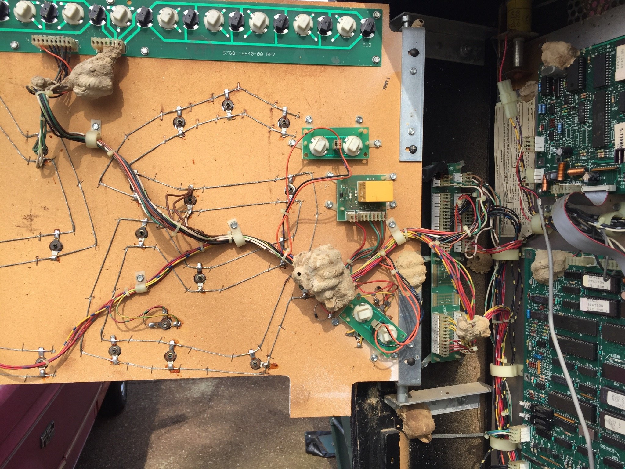