(Topic ID: 225038)

Rottendog WDP3211A testing - checking to see if I'm right...

By pb456

5 years ago


Topic Heartbeat

Topic Stats

  • 44 posts
  • 4 Pinsiders participating
  • Latest reply 5 years ago by GRUMPY
  • No one calls this topic a favorite

You

Linked Games

Topic Gallery

View topic image gallery

IMG_0362 (resized).JPG
image060_r (resized).jpg
image057_r (resized).jpg
pasted_image (resized).png
IMG_0275 (resized).JPG
IMG_0276 (resized).JPG
#1 5 years ago

Having trouble with a High Speed - was working great after the WDP3211A install. Late Friday night, thing shut down and would not come back up. Bad burning smell. Visual inspection only yielded potential burn on R7 on the display driver board.

Prior to the WDP3211A install, had display #2 burn out on me.

Replaced display driver board with known good unit, replaced display #2 also. Prior to WDP3211A, the 100V section on the original power supply took heavy heat damage and burned the 100V diode and the 202 transistor, so I purchased a WDP3211A - thinking I didn't want to run through replacing parts again.... but I may just do that anyhow.

1. PSU replaced.
2. Display driver board replaced.
3. Display #2 replaced.
4. No other displays witnessed faulty.

Now, disconnecting everything from the Rottendog WDP3211A but the two 3x connectors, CN1x12 and CN3x9, and powering on, I'm trying to get DC voltages across the fuses -F4, 5, 6, 7 - but I get nothing. The fuses pass continuity test.

I see the test points on the board, but not sure what ground I should be using, as connecting to the test points and CN6x15's ground pins (1, 11-15) yield no voltage.

I've verified that the system is getting AC as the aux connector inside the box works and is supplying 115VAC.

Haven't tested the transformer, not sure where to start, but have seen a few on here from posters wiser than I.

Thoughts?

IMG_0275 (resized).JPG
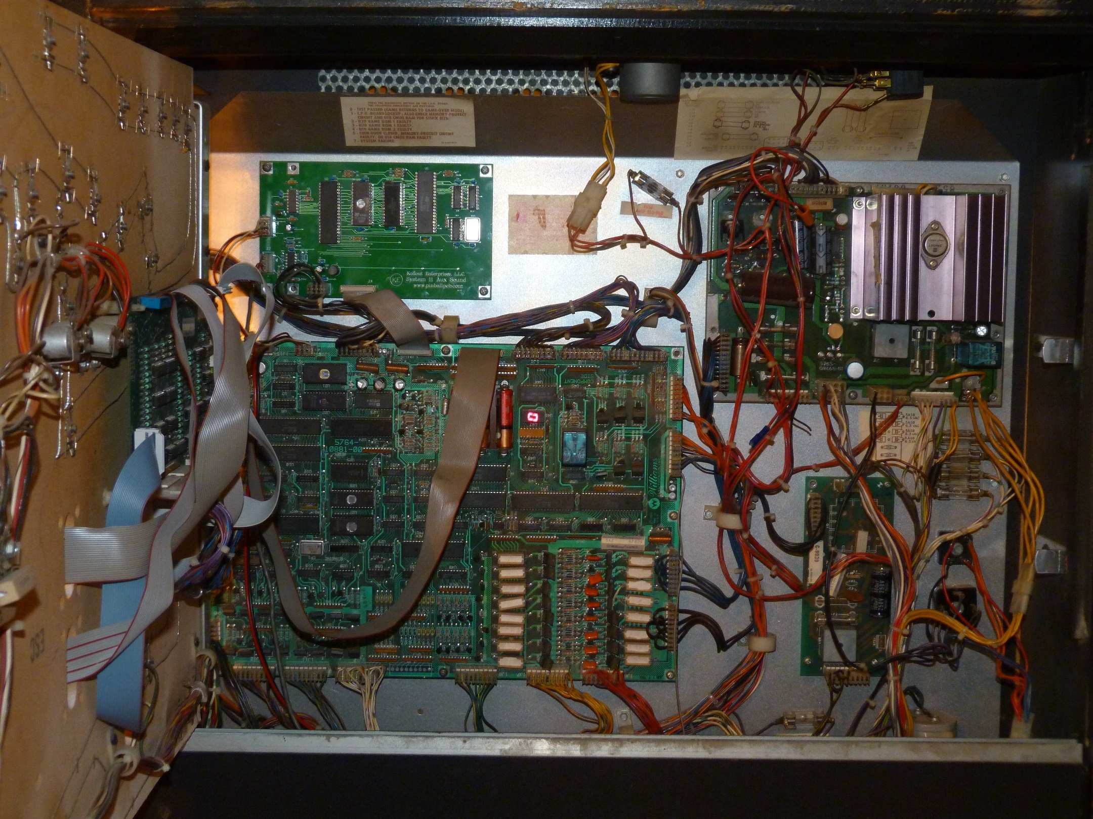
IMG_0275 (resized).JPGIMG_0276 (resized).JPGIMG_0276 (resized).JPG
#2 5 years ago

Please clarify "Now, disconnecting everything from the Rottendog WDP3211A but the two 3x connectors, CN1x12 and CN3x9, and powering on, I'm trying to get DC voltages across the fuses -F4, 5, 6, 7 - but I get nothing. The fuses pass continuity test."

Are you actually trying to measure the voltage 'across' the fuses? Or are you measuring from the fuse to ground?

#3 5 years ago

You may have burnt the main fuse down by the service outlet. The service outlet still works when the fuse is bad.

#4 5 years ago
Quoted from G-P-E:

Please clarify "Now, disconnecting everything from the Rottendog WDP3211A but the two 3x connectors, CN1x12 and CN3x9, and powering on, I'm trying to get DC voltages across the fuses -F4, 5, 6, 7 - but I get nothing. The fuses pass continuity test."
Are you actually trying to measure the voltage 'across' the fuses? Or are you measuring from the fuse to ground?

I'm trying to measure the voltage across the fuses.

#5 5 years ago
Quoted from GRUMPY:

You may have burnt the main fuse down by the service outlet. The service outlet still works when the fuse is bad.

I will check this. TY.

#6 5 years ago

Trying to measure across the fuses won't work. Unless the fuse is open or burned out, a fuse is a dead short. Voltage on the left side will be exactly the same as the voltage on the right so there won't be any voltage to read there (ok, maybe a few micro-volts difference).

F4 and F7 need to be measured with respect to ground -- black meter lead on ground.

#7 5 years ago
Quoted from GRUMPY:

You may have burnt the main fuse down by the service outlet. The service outlet still works when the fuse is bad.

Sure as heck, the 8A 125V fuse (slow-blow?) was completely kablooey.

#8 5 years ago
Quoted from G-P-E:

Trying to measure across the fuses won't work. Unless the fuse is open or burned out, a fuse is a dead short. Voltage on the left side will be exactly the same as the voltage on the right so there won't be any voltage to read there (ok, maybe a few micro-volts difference).
F4 and F7 need to be measured with respect to ground -- black meter lead on ground.

Ok. I'm going to replace the main fuse which was kaput and test again, thanks!

#9 5 years ago

So - it keeps blowing the 8A fuse in the service outlet. I'm going to look inside the box (with the mains unplugged of course!) to see if there's something shorted there, as well as the power cord itself.

#10 5 years ago

Opened the service outlet box, nothing looks cooked, pulled up the switch, same. Just a little dirt, is all.

Redid power cord end, still blows that 8A in the service outlet box. Will work on it again tomorrow hopefully, thanks for any suggestions.

#11 5 years ago

There is a piece inside the metal box where the fuse is that looks like the pic provided. It may have shorted. You can test it with an ohm meter. UNPLUG the cord from the wall outlet first. If it has a low reading it is bad. The schematics call it VR1, but it is a metal oxide varisistor like this.https://www.mouser.com/Circuit-Protection/Varistors/_/N-5g3h/

pasted_image (resized).pngpasted_image (resized).png
#12 5 years ago
Quoted from GRUMPY:

There is a piece inside the metal box where the fuse is that looks like the pic provided. It may have shorted. You can test it with an ohm meter. UNPLUG the cord from the wall outlet first. If it has a low reading it is bad. The schematics call it VR1, but it is a metal oxide varisistor like this.https://www.mouser.com/Circuit-Protection/Varistors/_/N-5g3h/[quoted image]

Yes, it's definitely shorted. I'll get it replaced and post back. Thanks!

#13 5 years ago

Any ideas on what I could use for a replacement part? Would all of the varistors you posted on the search work?

@grumpy

#14 5 years ago

https://www.greatplainselectronics.com/proddetail.asp?prod=V130LA20AP

https://www.marcospecialties.com/pinball-parts/5017-09044-00

Here is a couple places to buy a MOV.
The one you need must be for the correct line voltage. (130 volts)

#15 5 years ago

Also you can remove the mov and the game will function correctly without it, but you will not be protected from a lightning strike. You can finish your testing while waiting for this to arrive, but unplug it when not in use until its replaced.

#16 5 years ago
Quoted from GRUMPY:

Also you can remove the mov and the game will function correctly without it, but you will not be protected from a lightning strike. You can finish your testing while waiting for this to arrive, but unplug it when not in use until its replaced.

Replaced the MOV, keeps blowing the 8A fuse on the circuit box. I've tested continuity across the switch, and when connected to the 3x3 connector to the transformer, all poles show continuity. Disconnected from the transformer, switch shows continuity as expected. Do you know of a pinout or schematic for the transformer I can look at, or is this behavior normal?

#17 5 years ago
Quoted from pb456:

Replaced the MOV, keeps blowing the 8A fuse on the circuit box. I've tested continuity across the switch, and when connected to the 3x3 connector to the transformer, all poles show continuity. Disconnected from the transformer, switch shows continuity as expected. Do you know of a pinout or schematic for the transformer I can look at, or is this behavior normal?

Do you still have the power supply connected? If so then disconnect all connectors on the power supply, replace the 8 amp fuse and turn on the power. Did the fuse blow now?

#18 5 years ago
Quoted from GRUMPY:

Do you still have the power supply connected? If so then disconnect all connectors on the power supply, replace the 8 amp fuse and turn on the power. Did the fuse blow now?

PSU is disconnected, all devices upstream of the transformer are as well (only two connectors).

Fuse does blow (when turning on power) without anything connected to the transformer. The 3x3 connector between main and transformer is connected when the fuse blows (when turning on power). When the 3x3 connector is not connected, the fuse is good (when turning on power).

#19 5 years ago
Quoted from pb456:

Fuse does blow (when turning on power) without anything connected to the transformer.

There is still one more thing to check, lower right corner of the back box there are 2 bridge rectifiers. One has 2 blue AC wires and the other has 2 red AC wires, cut one red and cut one blue wire off and replace the fuse and connect the transformer and power up. Does it blow now?

#20 5 years ago

In High speed there should be an inline connector before the bridges. You may not need to cut one of the AC lines to each bridge. Just unplug this connector.

#21 5 years ago
Quoted from Cheddar:

In High speed there should be an inline connector before the bridges. You may not need to cut one of the AC lines to each bridge. Just unplug this connector.

Plugged into the transformer 3x3 connector (first pic) blows the fuse, even when the two connectors on the output side of the transformer (second pic) are disconnected...

image057_r (resized).jpgimage057_r (resized).jpgimage060_r (resized).jpgimage060_r (resized).jpg
#22 5 years ago
Quoted from GRUMPY:

There is still one more thing to check, lower right corner of the back box there are 2 bridge rectifiers. One has 2 blue AC wires and the other has 2 red AC wires, cut one red and cut one blue wire off and replace the fuse and connect the transformer and power up. Does it blow now?

I will check this also - but I have a bad feeling about the transformer, thanks for your help!

#23 5 years ago
Quoted from pb456:

Plugged into the transformer 3x3 connector (first pic) blows the fuse, even when the two connectors on the output side of the transformer (second pic) are disconnected...[quoted image][quoted image]

There's a connector like this in the head near the bridges. Not sure it disconnecting the lower connectors bypasses the bridges

#24 5 years ago
Quoted from GRUMPY:

There is still one more thing to check, lower right corner of the back box there are 2 bridge rectifiers. One has 2 blue AC wires and the other has 2 red AC wires, cut one red and cut one blue wire off and replace the fuse and connect the transformer and power up. Does it blow now?

Ok, this is what you were talking to - these are the bridge rectifiers I have in my backbox.... So cut one red from the top and one blue from the bottom, correct?

Is the top for MPU and GI, and the bottom for solenoids?

Cheddar GRUMPY

Thanks so much for your assistance, both of you!

IMG_0362 (resized).JPGIMG_0362 (resized).JPG

#25 5 years ago
Quoted from pb456:

Ok, this is what you were talking to - these are the bridge rectifiers I have in my backbox.... So cut one red from the top and one blue from the bottom, correct?
Is the top for MPU and GI, and the bottom for solenoids?
cheddar grumpy
Thanks so much for your assistance, both of you!
[quoted image]

If you back up that harness a few.inches is there a connector? The high speed I worked on last weekend had one.

#26 5 years ago

One bridge makes power for the coils, and the other bridge makes power for the insert lamps.

#27 5 years ago
Quoted from pb456:

Ok, this is what you were talking to - these are the bridge rectifiers I have in my backbox.... So cut one red from the top and one blue from the bottom, correct?

Yep.

#28 5 years ago
Quoted from Cheddar:

If you back up that harness a few.inches is there a connector? The high speed I worked on last weekend had one.

When you say back up, do you mean travel down the wiring connected to the bridge rectifiers and look for a connector?

#29 5 years ago

I'm trying to prevent you from having to cut those wires. If you look at the very bottom right of this image you will see the connector I am talking about. http://www.pinballpcb.com/images/AuxSound/S11AuxSoundinHS.jpg

It carries the AC lines to the bridges. If you have this connector you can unplug it instead of cutting the lines.

#30 5 years ago
Quoted from pb456:

When you say back up, do you mean travel down the wiring connected to the bridge rectifiers and look for a connector?

Exactly, the blue and red AC lines should go into a connector within 6 inches.

#31 5 years ago
Quoted from Cheddar:

Exactly, the blue and red AC lines should go into a connector within 6 inches.

Yes, I see it now. I'll try that method.

#32 5 years ago

Yeah, no-go. Fuse blew even with that connector disconnected from the BRs.

#33 5 years ago

By-the-by, using 8A 250V SB fuses. Rewired fuse connector also. Fuse does not blow when power applied and disconnected from transformer. Any idea on where to get a replacement if that's the prognosis?

#34 5 years ago

Any melting or burning on that transformer?

Checking to see if a transformer is bad is outside my expertise. If you can identify the AC pairs you can check the resistance on each pair but without a reference for the normal resistance you won't know unless the resistance is almost nothing. That's why physical evidence (melting) makes it easy to diagnose.

And that exhausts my knowledge about the transformer. Good luck.

If you need a replacement here's the model number 5610-10897-00

#35 5 years ago
Quoted from Cheddar:

Any melting or burning on that transformer?
Checking to see if a transformer is bad is outside my expertise. If you can identify the AC pairs you can check the resistance on each pair but without a reference for the normal resistance you won't know unless the resistance is almost nothing. That's why physical evidence (melting) makes it easy to diagnose.
And that exhausts my knowledge about the transformer. Good luck.
If you need a replacement here's the model number 5610-10897-00

No melting. The closest I have to evidence the transformer is bad was the terrible smell for about 3 days (with the system disconnected) and the fuses blowing. Thanks for the PN. I'll see if there's an alternator shop in town that would test these.

#36 5 years ago

Let me posit this - would a defective P2 score display board have caused this? Defective P2 score display + display driver?

GRUMPY Cheddar

#37 5 years ago
Quoted from pb456:

Let me posit this - would a defective P2 score display board have caused this? Defective P2 score display + display driver?
grumpy cheddar

Not unless someone put a 30 amp fuse in F-1 on the power supply. F-1 should be a 1/4 amp fuse.

#38 5 years ago
Quoted from GRUMPY:

Not unless someone put a 30 amp fuse in F-1 on the power supply. F-1 should be a 1/4 amp fuse.

I found a fuse in F1 that was larger than it should have been - I think it was 8A. Found it when I was looking at the boards when it quit the first time. Damn it.

#39 5 years ago

I figured I'd replace it with the proper fuse, and the damaged PSU, and Display Driver and have a working system. I figured wrong.

#40 5 years ago

And yes, I should have checked the fuses when I got it. /* Sad panda /*

#41 5 years ago
Quoted from pb456:

I think it was 8A.

That may have been large enough to do damage.

#42 5 years ago
Quoted from GRUMPY:

That may have been large enough to do damage.

Not that I doubt that - but a bad display could kill the transformer with the incorrect fuse in F1?

Good to know.

1 week later
#43 5 years ago

GRUMPY Thank you for your help.

PSU was good, display board was good, transformer was bad.

Found a replacement on eBay.

Not as easy to come by as I would have hoped!

#44 5 years ago
Quoted from pb456:

transformer was bad.

That doesn't happen very often.

Promoted items from Pinside Marketplace and Pinside Shops!
$ 27.95
Eproms
Pinballrom
 
$ 35.99
Eproms
Matt's Basement Arcade
 
$ 53.99
Eproms
Matt's Basement Arcade
 
Wanted
Machine - Wanted
Red Oak, TX
$ 10.00
Playfield - Protection
UpKick Pinball
 
$ 20.00
Cabinet - Decals
Pinball Haus
 
$ 15.00
Playfield - Decals
Metal-Mods
 
6,500
Machine - For Sale
Orange, CA
From: $ 3.50
Playfield - Other
Rocket City Pinball
 
$ 15.00
Playfield - Other
RobTune
 
$ 35.00
Cabinet - Other
Rocket City Pinball
 
$ 54.99
Cabinet - Shooter Rods
Lighted Pinball Mods
 
$ 10.00
Playfield - Protection
UpKick Pinball
 
$ 15.00
Playfield - Toys/Add-ons
RobTune
 
$ 69.00
Gameroom - Decorations
Pinball Pimp
 
$ 18.00
Electronics
Yorktown Arcade Supply
 
Wanted
Machine - Wanted
Fort Lauderdale, FL
$ 12.00
Playfield - Toys/Add-ons
UpKick Pinball
 
4,995 (OBO)
Machine - For Sale
Dunakeszi
Great pinball charity
Pinball Edu

Reply

Wanna join the discussion? Please sign in to reply to this topic.

Hey there! Welcome to Pinside!

Donate to Pinside

Great to see you're enjoying Pinside! Did you know Pinside is able to run without any 3rd-party banners or ads, thanks to the support from our visitors? Please consider a donation to Pinside and get anext to your username to show for it! Or better yet, subscribe to Pinside+!


This page was printed from https://pinside.com/pinball/forum/topic/rottendog-wdp3211a-testing-checking-to-see-if-i-m-right and we tried optimising it for printing. Some page elements may have been deliberately hidden.

Scan the QR code on the left to jump to the URL this document was printed from.