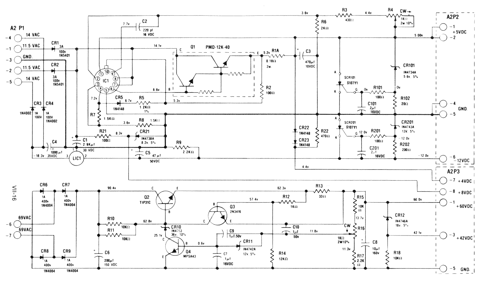
C1 (Cinput) is a Nichicon UPW series cap. This is a low impedance cap which is a good thing.
C3 (Coutput) is a Nichicon UVX series cap. This is a standard but high temp cap - which is NOT a good type to be used as a switching regulator output cap.
Standard practice on switching supplies is to always use a low impedance caps at the input and output of a switching regulator, usually paralleled caps are used to reduce ESR and increase ripple current capabilities.
For the input cap, low-ESR is often optional but a high ripple current rating is a must. Increasing the ripple current rating is often achieved by using a low ESR cap.
For the output cap - both high ripple current rating and low ESR values are a must.
The cap he used for C3 is no longer available so I can't look up diameter and lead pitch. I'm guessing that would be 16mm diameter with 7.5mm lead spacing. Assuming he used the correct capacitance and voltage values, I would go to a Nichicon UPW1C472MHD or Panasonic EEUFC1C472.
Regarding R21 -- 100 ohms is a bit low:
If the DC in is 12V (normally higher for this board)--
Voltage across R21 = 12V - zener voltage 8.1 = 3.9V
Current through R21 = = 3.9V / 100 ohm = 39mA
Power dissipated by R21 = 3.9V x 39mA = 152mW. A bit high for a half watt resistor but acceptable.
Power dissipated by CR21 = 8.1 x 39mA = 0.31W. That works but is quite high for a 1 watt zener diode. It will get hot but shouldn't burn - heat created will result in shortened life span.
In real life - the DC voltage on a System 1 supply is normally a bit higher than 12V which increases the above wattage values and makes things worse.
Going to a 470 ohm resistor will reduce zener power to about 20% of what it was or about 0.062W - MUCH better.
I normally use 390 ohms which would reduce power to about 25% of that 0.31W rating or about 0.077W -- also much better.
Going to too large of a resistor value will cut off current flow to the zener diode (below zener diode "knee" current rating).
The zener diode requires a minimum of just under 1mA to operate properly.
100 ohm resistor provides 39mA -- high enough... actually too high.
390 ohm resistor provides 9.75mA -- plenty of current to keep zener operating.
470 ohm resistor provides 7.8mA -- also plenty of current to keep zener operating.
So a resistor in the 390 or 470 range will work. Can actually go higher but I never bothered to calculate where the limit is.
Going too high will also create an excessive voltage drop across R21 depending on load from displays (normally quite low).
To prolong life of R21 and CR21 and stay in proper voltage ranges - I recommend you change R21 to 390 to 470 ohms rated at 1/2 watt.
AND - rant mode on...
Another strange thing I noticed - there is no bulk capacitance for the low voltage input!
The input capacitance is the switching regulator's value used for when you already have a DC input to the circuit, it is NOT intended to be part of the DC rectification! This is a low ESR, high ripple current cap placed 'close to the device'. *The rectified voltage is supposed to already be filtered prior to the switching regulator's input cap*. This board goes straight from bridge rectifier to the regulator input cap and then the regulator. There is no dedicated bulk capacitance,he combined the bulk capacitance and the switcher input capacitance! No wonder these were cheap.
Normal design of this type would go from rectification circuit CR1 & CR2 to a bulk capacitor. Bulk capacitance is used for basic DC filtering and are sized to supply average DC current without sags and absorb current swings.
From bulk capacitor - voltage the goes to the Cin cap which are placed as close to possible to the regulator. The Cin cap is used to facilitate the high current spikes normally created by the switching type regulator.
The bulk and input caps are normally not combined into a single cap - let alone one with such a small value. Yet, somehow his board works. In the electronics world, we call this type of design "Muntzing". Muntzing is the practice of reducing the components inside an electronic device to the minimum required for it to function long enough to get past warranty.

 Omaha, NE
 Ajax, ON

