Quoted from WhiskeyTango:
I'm encountering the same issue and this is an interesting solution. Would you share a picture showing it with the play field up?
Sure.
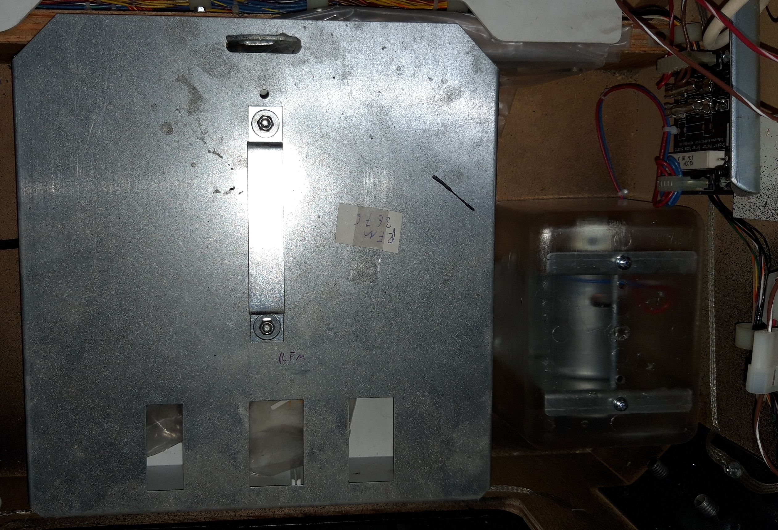
This kit uses a different concept for covering the weights than the one that  applejuice used. That one just covers the weights, this one covers the whole assembly. I assume that the idea is to keep errant wires, etc. out of the swing of the weights rather than act as a dust cover, so I'm not worried about cutting into the middle part. Also, I'm pretty sure that there's nowhere in the corner you could mount this one without interference. Obviously I didn't think about this when I placed the motor, and I'm really glad that the foot fell in a location where it was only conflicting with the cover, and not the frame of the motor, or even worse, the path of one of the weights!
In time, if the cut bugs me, I'll probably end up designing a 3D printable set of end covers.
Also, on a side note, there's no path in the cover for the wires to route through, so there will be some cutting involved regardless. Actually, there is a hole on the top of the cover that I assumed was to catch the mounting screw for the fuse holder. Since this mod involves cutting the connector off, I suppose you could thread the wires through that hole, but then you'd need to mount the fuse somewhere else.
 2019-07-18 09.28.24 (resized).jpg2019-07-18 09.28.34 (resized).jpg
 Austin, TX
 Leeds
Leeds
 Wiener Neustadt
 Tilburg
 Köln
Köln
 Milano
 Pyongyang

