(Topic ID: 180997)

Rectifier Bally paragon

By StratDoc

7 years ago


Topic Heartbeat

Topic Stats

  • 210 posts
  • 7 Pinsiders participating
  • Latest reply 7 years ago by Quench
  • Topic is favorited by 10 Pinsiders

You

Linked Games

Topic Gallery

View topic image gallery

Paragon_SDB.png
IMG_2267 (resized).JPG
IMG_1414.gif
image (resized).jpeg
Paragon_Snda.jpg
image (resized).jpeg
IMG_2122 (resized).JPG
IMG_2118 (resized).JPG
leds_pkg_b.jpg
There are 210 posts in this topic. You are on page 4 of 5.
#151 7 years ago
Quoted from StratDoc:

The reading across E and B is 1.35 and the same across B and C. Q2 reads E and B 9.8 and 13 across B and C.

Can you tell us how you measured it? The results don't sound right.
Actually these transistors can be tested in diode mode. A good one of these transistors will measure about 0.65v between B-E and also between B-C in diode mode.

BTW, in your picture of the board, U11 looks cooked by the marks around pins 2-5, possibly U4 too with the bubble above pin 4. Do any of the ICs on the board get hot after a few minutes?

#152 7 years ago

Yes, resistance in ohms. Nothing on the board gets hot. Have it one for the past five minutes.

#153 7 years ago

So three legs NPN transistor I think. Set multimeter to ohms 20k selected on multimeter. Negative to E and positive to B. Negative to c and positive to B.

#154 7 years ago

Do you have one of these meters: ?
https://pinside.com/pinball/forum/topic/kiss-pinball-79/page/3#post-3624061
With this basic 2N3904 NPN transistor, measure it in diode mode putting the red meter lead on the 'B' pin. The black meter lead to 'E' will probably measure high 800 - low 900 and similar result to the 'C' pin using a cheap multi-meter like the pic above.

A fluke brand meter will probably measure in the range of 0.64 - 0.70 in diode mode between B-E and also B-C.

If the transistor is out of circuit, reversing the meter leads with this NPN transistor should give you open circuit readings.

You can pull this Q3 transistor off the board for now - it isn't critical for generating tones. A working board will produce some wrong tones without Q3, but you're only getting buzzing and the board has other issues.

Having said all this, if the only test tool you have is a multi-meter, it isn't really going to cut it in diagnosing this board. You might want to consider contacting barakandl and seeing if he can repair/replace this sound board. He fixes a lot of these.

#155 7 years ago

Here is my multimeter - ace hardware special. It does not have a diode setting. I do have a logic probe as well. I will contact him and move on to working on other issues.

So everything boots up, I can place credits on the machine and the switches are working registering points. Only two solenoids fire in diagnostic mode - 13 and 14. All coils fire when I touch a ground to the non-banded side of the coil. Q5,6,7,8,9,15,18,19 do not fire when I touch a ground to the transistor. All others are working. No coils or solenoids work in game.

image (resized).jpegimage (resized).jpeg

#156 7 years ago

I now have voltages to the playfield. Raising and lowering it jiggled some things loose. I still have the issues with the solenoids not firing in game - see previous post.

#157 7 years ago
Quoted from StratDoc:

Q5,6,7,8,9,15,18,19 do not fire when I touch a ground to the transistor.

Q5, Q6, Q7 and Q18 are not connected to any coils.
Q8 drives the Treasure Chamber Saucer
Q9 drives the Left Pop Bumper
Q15 activates the Flipper Enable relay on the SDB (you should hear it click)
Q19 activates the Coin Lockout coil on the front door

I'll bombard you with a lot to test here to isolate the issue more quickly. Try and do the following step by step.

Put the game in solenoid test mode. Measure the voltage at pin 19 of IC U2 on the SDB. It should be around zero volts - this signal being low opens communication from the MPU board to the SDB. If it measures steady logic high (3.5 - 5V) then check it at the source (pin 19 of U11 at the MPU board). If it's measuring high here at the MPU board then this is a problem. If it's low, then there's a connector issue from MPU J4 pin 10 to the SDB J4 pin 7.

If the above signal pin 19 of U2 on the SDB measures ok (Low), try to manually activate solenoids with the logic lines. During the solenoid test *very briefly* ground the following pins at U2 on the SDB:
U2 pin 8 should fire the Treasure Chamber Saucer
U2 pin 11 should fire the Right Pop Bumper
U2 pin 15 should fire the Left Slingshot
U2 pin 16 should fire the Right Slingshot

If these solenoids don't fire, the issue is on the SDB probably with the ICs. If they do fire, then check the solenoid select signals from the MPU board to the SDB (stay in Solenoid Test mode).
With your logic probe, probe pins 20,21,22,23 of U2 on the SDB. When solenoids are not firing these pins should indicate High. When solenoids are being activated, these signals at different times will pulse Low (depending on the solenoid being selected to activate). If one or more of these signals never pulse low, check these signals back at the source (MPU board at U11 on pins 13,12,11,10 respectively). If they all pulse at some point on the MPU board you have connector issues from the MPU board J4 pins 1,2,3,4 to the SDB at J4 pins 3,4,5,6 respectively.

Good luck!

#158 7 years ago

Here is what I learned.

Pin 19 at U2 on the SDB is low at 1.4 volts.
I can manually activate the solenoids by ground pins 8,11,15,16.
Pins 22,23 at U2 on SDB pulse high/low. Pins 21,22 do not pulse. They stay high.
U11 is a square chip on the altek board with 40 pins. Assuming top left is pin 1 on the left had side of the chip and then move counterclockwise around the chip, I do not get pulses at 10,11,12,13.

image (resized).jpegimage (resized).jpeg

#159 7 years ago

Here is a link to the Altek board schematics - http://www.allteksystems.com/pdfs/MPU_Rev_L_Schematic.pdf. on this board the solenoid signal appears to come from U2. I cannot really tell from the schematics the pin layout. If I start at top left of the chip and go down 10 pins I get a high/low pulse for 10,11,12,13 as diagnostics cycles through the solenoid test. No other pins pulse on the chip.

#160 7 years ago

*sigh* why couldn't Alltek keep the primary chip location numbers standard.
If you have the "L" revision MPU board, replace everything I said above about U11 on the MPU board with U2 on the MPU board. And yes, pin 1 of U2 (6821 chip) is at top left corner and counts anticlockwise.

#161 7 years ago

Pulled the wires for both plugs, and all looked fine. Hit the connectors with a file and ensured connector pins are making good contact. No change. Could it be resistors R1-R4 on the SDB?

#162 7 years ago
Quoted from StratDoc:

Could it be resistors R1-R4 on the SDB?

Unlikely, but you can measure them if you want. Set your meter to resistance ohms mode on the 200k range.
If R1-R4 are colored orange-orange-orange-gold, you should get readings around 33k
If R1-R4 are colored brown-black-yellow-gold, you should get readings around 100k

Suggest you check the solenoid select signals back at the MPU board at U2 on pins 13,12,11,10 during solenoid test mode with your logic probe. They should all pulse low at various times during the solenoid tests.

#163 7 years ago

I tested U2 on MPU and 10,11,12,13 pulse high/low during diagnostic test. I also resoldered pons 3,4,5,6 on the SBD abandon their connections to the jumper pins and U2 on the SDB. None of the traces look problematic.

The resistors are orange, orange, orange,,gold and measure in spec between 35 and 33 ohms.

BTW- Barakandl no longer works on boards but he is brining a bally sound board to market in a couple of weeks.

#164 7 years ago

Sorry, I just re-read the emails above and missed some things.
The 1.4 volts you measured at pin 19 of U2 on the SDB during the solenoid test is not low enough. It should be 0.8V or lower.
Can you ground this pin during the solenoid test and see if any coils activate?

I also gave you wrong pins to ground for manually testing the solenoid select logic lines on the SDB.
Disconnect the J4 connector from the SDB and leave it disconnected. Run a wire from ground to J4 pin 7 on the SDB and leave the wire there making sure it's not touching other pins.
Power the machine on. If any coils lock on (they shouldn't), abort immediately.
In attract mode, if you then *very briefly* jumper another wire from ground to the SDB on:
J4 pin 3 should fire the Treasure Chamber Saucer
J4 pin 4 should fire the Right Pop Bumper
J4 pin 5 should fire the Left Slingshot
J4 pin 6 should fire the Right Slingshot

If solenoids don't activate, then U2 (the 24 pin 74L154 chip) on the SDB is faulty.

#165 7 years ago

Okay, so maybe getting closer. Grounding pin 19 in solenoid test and no coils fire.

Ground J4 pin 7 from SDB in attract made no coils lock on.

Ground to j4 pin 3 on SBD no coils fire. Same for pin4, pin5, and pin6.

#166 7 years ago

Ordered a U2 - 74L154 - chip for the SDB. Should be in by mid or end of week.

#167 7 years ago
Quoted from StratDoc:

Ground to j4 pin 3 on SBD no coils fire. Same for pin4, pin5, and pin6.

If you did this while J4 pin 7 was still connected to ground, then yes the 74L154 is faulty.
Some of the pins I incorrectly asked you to check up top actually indicate U3 and U4 are probably ok (not dead).

Good luck with the replacement of U2.

#168 7 years ago

I misread your post. I removed the ground to J7 when testing the other pin connections. I need to go back and recheck with pin 7 still attached to ground. No big deal, and the U2 chip I ordered with some other things needed. Let check and post back.

Disconnected j4 and connected a wire to ground and pin7. Left the ground to pin 7 in place and grounded another wire and touched pins 3,4,5,6. No coils fired. So it sounds like it is the U2 chip. it should be here by midweek. I will keep you posted.

#169 7 years ago

I replaced U2 on the SDB and that did the trick. During the diagnostic solenoid test all coils fire :party

The only thing now is the sound board and maybe the lamp driver board - have not check it yet.

On the sound board I have slowly started replacing all ICs with no luck. Still just get a loud buzz and can adjust the sound with the the pot on the board. I have replaced all capactors, and q1, q3, u5, u4, u7, u9, u10. U1, 2, and 8 I have not been able to find. Those are the last three to replace plus U3 which is the game specific rom. All voltages at correct on the board.

#170 7 years ago
Quoted from StratDoc:

I replaced U2 on the SDB and that did the trick.

Great!

Is there an issue with the lamp board or you haven't plugged it in yet?

When you turn the volume all the way down on the sound board, does the buzzing go away?

On the sound board, what happens if you jumper a wire from TP2 (GND) to pin 1 of U8? Grounding this pin eliminates nearly all the logic chips on the audio signal and leaves you with the amplifiers only.

#171 7 years ago

Al sound /buzzing goes away when I jump a wire from board ground to u8 pin 1. Buzzing does not go away when I turn down the sound.

#172 7 years ago

Found this website on repairing Bally sound boards. There is a section on testing high/low pulse on u1, u2, and U3. None of the chips on my board pulse. http://www.pinball4you.ch/okaegi/rep_soundold.html

#173 7 years ago
Quoted from StratDoc:

Al sound /buzzing goes away when I jump a wire from board ground to u8 pin 1.

This essentially mutes the volume to the input of the pre-amp (U9).

Quoted from StratDoc:

Buzzing does not go away when I turn down the sound.

Strange. If the buzzing goes away by muting the volume at the pre-amp, then the same should happen when you adjust the volume all the way down to the ouput amp (U10).
I think "all the way down" is actually fully clockwise (i.e. opposite to a standard audio volume control).
Does rotating the volume control make any change at all?

Are you getting any pulsing on pin 9 and pin 11 of U11?

For U3 to pulse, it requires U1 and U2 to be working/pulsing.

U1 and U8 are "4049" chips. Try searching for CD4049.
U2 is a 4042 chip. Try searching for CD4042.
These chips are easily available.

#174 7 years ago

RT3 all the way clockwise increases the buzzing. No pulse pin9 and pin 11 of u11.

#175 7 years ago

If you're getting no pulsing on the output pins of U1 and U2 they should be replaced.

Can you give me the logic probe levels on all 16 pins of the PROM at U3?

#176 7 years ago

PROM U3 has no signal on any pins

#177 7 years ago
Quoted from StratDoc:

PROM U3 has no signal on any pins

Try measuring the voltages on the pins with your multi-meter instead.

#178 7 years ago

Voltages

Pins 1 - 8 measure approximately .08vdc

Pin 9 - 4.49
Pins 10&11 0.00
Pin 12- 4.48
Pin 13- 3.6
Pin 14- 4.42
Pin 15- 0
Pin16 -0

#179 7 years ago

??? Pin 16 is the 5V power pin. You've lost power to the chip..

#180 7 years ago

All test points are good. Let me recheck..

#181 7 years ago

All test pints on the board are correct.

#182 7 years ago

I am thinking it could be a bad socket. It is the original. I pulled the socket and will run to Radio Shack to pick up another 16 pin socket.

#183 7 years ago

SUCCESS! Sound board is repaired

I replaced the U3 socket and replaced u1 and u2. Basically the whole darn board has been rebuilt.

Now on to testing the lamp board. With any luck I will be playing the pin by this evening or tomorrow.

Quench, you are the geatest!

#184 7 years ago

A significant number of lamps out, including the entire backbox. What is the best way to start trouble shooting the lamp driver board? I do not have a test rig.

#185 7 years ago

With the backbox switched lamps, there's a common braid wire to all the switch lamps. Do you measure 5.4VDC along that common braid wire?

#186 7 years ago

No volts anywhere along the braid.

#187 7 years ago

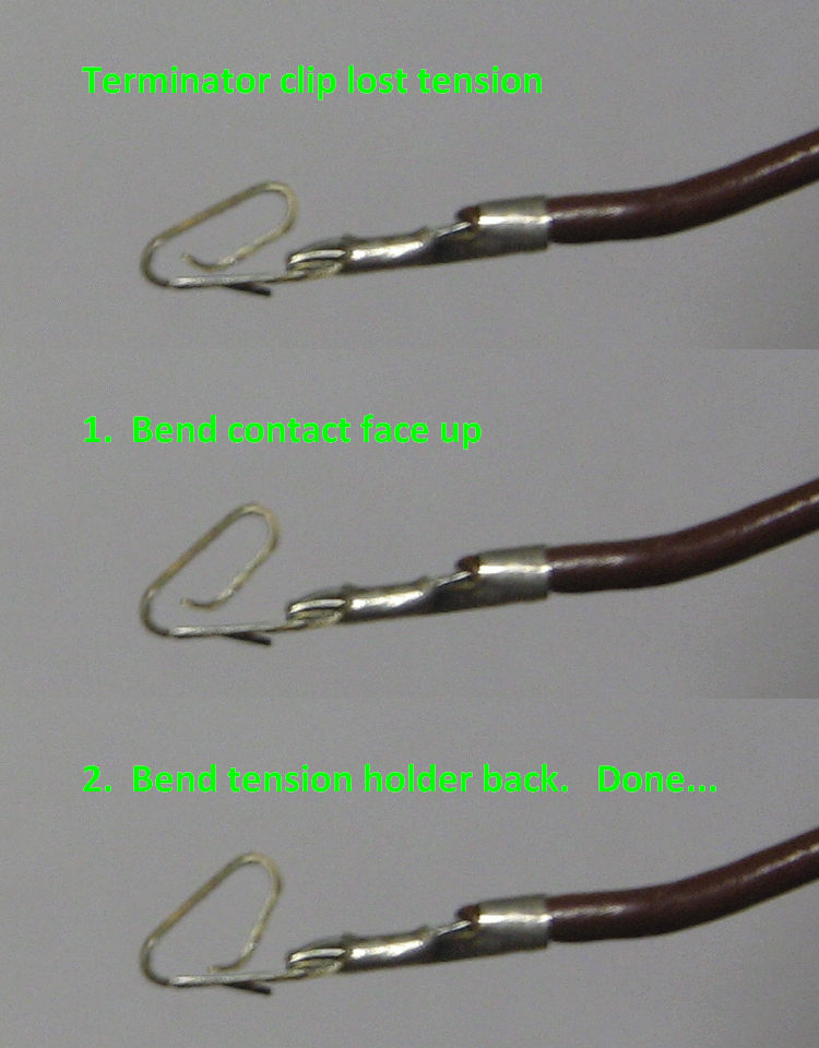
Are you getting 5.4V at TP1 on the rectifier board? If not does fuse F1 test ok?

#188 7 years ago

Yes, 5.5 at TP1 on rectifier board.

#189 7 years ago

With the work you did on the rectifier board, did you replace the terminals in the three connectors?
The blue wire in pin 6 of the J3 connector at the rectifier board carries the 5.4VDC power to the backbox switched lamps. Measure it there and determine if you have an open circuit on this wire to the backbox switched lamp braid.

How about the playfield switched lamps? Any/many working?

#190 7 years ago

I bought a replacement rectifier board. pin 6 has 6volts.

I would say 2/3rds of the switched lamps on the playfield are out.

I am going to repin J3.

#191 7 years ago
Quoted from StratDoc:

I would say 2/3rds of the switched lamps on the playfield are out.

If you can, go into lamp test mode and take a photo at the moment the 1/3 of the playfield lamps are on.

Have you replaced any of these lamps that are not coming on in the chance you have a large number blown lamps?

#192 7 years ago

I checked for blown bulbs and replaced. Two pics attached. One is my inventory of switched lamps not working. Some also have the associated transistor next to it.

image (resized).jpegimage (resized).jpeg

image (resized).jpegimage (resized).jpeg

#193 7 years ago

You have a list of the lamps that are out.
If you look at the lamp board schematic, you can trace them to the SCRs (the things that look like transistors) and then back upstream to the four "4514" chips that activate them. You may notice some things.

In the mean time, you can test the SCRs.
If you look at the small and large SCRs, some of them have the letters "C", "A", and "G" showing you how the pins are defined.
Jumper a wire from TP3 on the lamp board to the "G" pin on any SCR, and the lamp connected to it should light.

Try it with a few lamps that aren't working.
If a lamp lights, the problem could be upstream at 4514 chip or connections to the 4514 from the MPU board.
If a lamp doesn't light, then jumper a wire from ground (you can use "TP2 GND" on the lamp board) to the "A" pin on the SCR (for convenience, the larger SCRs have a metal tab/backing which is internally connected to the "A" pin). If the lamp now lights, the SCR is faulty.

#194 7 years ago

I jumped a wire fromTP3 to a "G" leg of each transistors. No lamps lit.

Jumping a wire from TP2 to to the "A" leg of each transistors causes one or two lamps to light but not others.

#195 7 years ago

The playfield switched lamp sockets have a common braid wire connected to them all at the base where the lamp socket screws to the playfield. This braid is the 5.4V power for the switched lamps.

The terminal on the tip of the lamp sockets where each have an individual color coded wire connects back to the lamp board at the "A" pins of the SCRs.

With switched lamps that aren't working, if you jumper a wire from ground to the colored wire on a lamp socket tip, the lamp should light up.
If it doesn't, the lamp is blown, or the lamp socket has poor (loose/corroded) connections to the lamp, or the 5.4V power on the base of the lamp socket is missing.
If the lamp lights up but not when you grounded the respective "A" pin of the SCR back at the lamp board, then you have a connection issue back at the lamp driver board connector.

#196 7 years ago

They light up when I touch the socket with a grounded wire.

I double checked connectors to backbox and playfield and found the main connctor was loose. I now have backbox lights.

I then tested each transistor leg "A" to ground found several that appeared bad. I replaced them but it did not help in all cases. For example, q48 controls the top right special saucer. I replaced the transistor but the lamp still did not work. If I touch a ground wire to leg "A" of the new transistor it lights. Other replaced transistors do the same.

#197 7 years ago

Quench,

Making progress but have hit another impasse. So in attract mode most of the lights now flash and sequence, but I still cannot get some lights to come on regardless of wether I connect to TP3 and touch leg G or ground and touch leg A of the corresponding transistor. I have replaced U1-U4 chips - this is why most of the lights now sequence and flash properly. Other things I should check? All sockets are good. I can ground a wire and touch the socket and get all non-working lights to work.

#198 7 years ago
Quoted from StratDoc:

Quench,
Making progress but have hit another impasse. So in attract mode most of the lights now flash and sequence, but I still cannot get some lights to come on regardless of wether I connect to TP3 and touch leg G or ground and touch leg A of the corresponding transistor. I have replaced U1-U4 chips - this is why most of the lights now sequence and flash properly. Other things I should check? All sockets are good. I can ground a wire and touch the socket and get all non-working lights to work.

Check for cold solder joints where the light connectors are attached to the board. Could also be a bad pin in the connector

#199 7 years ago
Quoted from StratDoc:

I still cannot get some lights to come on regardless of wether I connect to TP3 and touch leg G or ground and touch leg A of the corresponding transistor.

If grounding the colored wire at the lamp socket works, but grounding the "A" leg of the associated SCR doesn't, then that simply indicates a connector issue as zacaj mentioned because you've lost continuity from the lamp board to the lamp sockets on the playfield for those non-working lamps.

#200 7 years ago

Thanks. I am slowly making progress with your help. Two more lamps on this morning.

Q34 the waterfall special lamp is interesting. I cannot get it light except for grounding a wire to the socket, I ran trace wire from the pin connector to q34 and then from the associated resistor to the U chip. Still does not light. I have a couple of more with the same problem. Would this suggest a bad Molex connector?

Promoted items from Pinside Marketplace and Pinside Shops!
$ 69.00
Gameroom - Decorations
Pinball Pimp
 
From: $ 1.25
Playfield - Other
Rocket City Pinball
 
$ 18.00
Electronics
Yorktown Arcade Supply
 
3,600 (OBO)
Machine - For Sale
Mountainside, NJ
$ 179.00
Cabinet - Other
Pinball Pimp
 
From: $ 150.00
$ 10.95
Eproms
Pinballrom
 
4,200 (OBO)
Machine - For Sale
Springfield, MO
$ 15.00
Playfield - Decals
Metal-Mods
 
Trade
Machine - For Trade
Munster, IN
$ 10.00
Playfield - Protection
UpKick Pinball
 
$ 35.00
Playfield - Plastics
UpKick Pinball
 
From: $ 5.00
Cabinet - Other
UpKick Pinball
 
$ 69.00
Gameroom - Decorations
Pinball Pimp
 
$ 18.95
Eproms
Pinballrom
 
Great pinball charity
Pinball Edu
There are 210 posts in this topic. You are on page 4 of 5.

Reply

Wanna join the discussion? Please sign in to reply to this topic.

Hey there! Welcome to Pinside!

Donate to Pinside

Great to see you're enjoying Pinside! Did you know Pinside is able to run without any 3rd-party banners or ads, thanks to the support from our visitors? Please consider a donation to Pinside and get anext to your username to show for it! Or better yet, subscribe to Pinside+!


This page was printed from https://pinside.com/pinball/forum/topic/rectifier-bally-paragon/page/4 and we tried optimising it for printing. Some page elements may have been deliberately hidden.

Scan the QR code on the left to jump to the URL this document was printed from.