(Topic ID: 127933)

Pinball Electricity for Dummies

By Star_Gazer

8 years ago


Topic Heartbeat

Topic Stats

  • 151 posts
  • 41 Pinsiders participating
  • Latest reply 1 year ago by swinks
  • Topic is favorited by 50 Pinsiders

You

Linked Games

No games have been linked to this topic.

    Topic Gallery

    View topic image gallery

    diode11.gif
    download (2).jpg
    FOKLF2OH5JVY45Y.LARGE.gif
    Transistors.jpg
    capacitor-types.jpg
    images.jpg
    120px-Diode_pinout_en_fr.svg.png
    download.jpg
    OK.png
    FB_IMG_1432272766397.jpg
    check-mark-cancel-21305006.jpg
    Lamps_13.jpg
    ohmslaw.png
    Lamps_12.jpg
    Lamps_11.jpg
    Lamps_10.jpg
    There are 151 posts in this topic. You are on page 2 of 4.
    #51 8 years ago

    Wikipedia is your friend. Some very important stuff to understand:

    Ohm's Law
    Resistance & Conductance
    Current/Amperage

    http://en.wikipedia.org/wiki/Ohm%27s_law
    http://en.wikipedia.org/wiki/Electrical_resistance_and_conductance
    http://en.wikipedia.org/wiki/Electric_current

    Then you get into the more fun stuff:

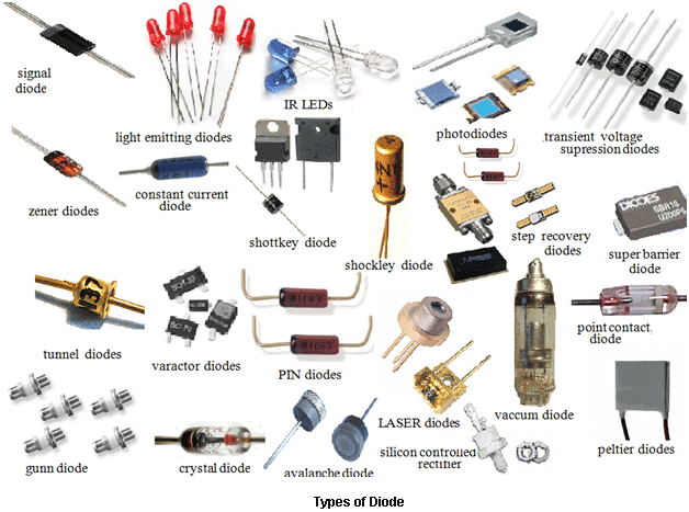
    Diodes
    Transformers
    Transistors and their wide varity of types and their various uses as both amplifiers and switches (N-Channel, P-Channel, Darlington, BJT's - JFET, MOSFET).

    http://en.wikipedia.org/wiki/Diode
    http://en.wikipedia.org/wiki/Transformer
    http://en.wikipedia.org/wiki/Transistor

    Then ICs (opamps, Logic ICs, OTAs, and specialty chips) and logic gates so you can identify their purpose in schematics:

    http://en.wikipedia.org/wiki/Integrated_circuit
    http://en.wikipedia.org/wiki/Logic_gate

    Don't worry so much about the formulas involved. For basic pin repair and maintenance, you really just have to be able to read the schematic and understand how the parts works in a section.

    http://en.wikipedia.org/wiki/Electronic_symbol

    #52 8 years ago

    Flashers are wired in series for sets that flash at the same time.

    #54 8 years ago

    All in all though, it isn't overly difficult to understand how these games work and how to read schematics for that matter. Breaking each component down into easy to understand examples helps.

    #55 8 years ago

    Electronics in general has nice real world examples, the only difference is that they're running at a much faster speed and obviously many factors smaller.

    Resistor - Think of a resistor as a damn in a river. The more logs in the river, the slower the water (current) flows. So the higher the value of the resistor, the slower the water flows. There are lots of different kinds of resistors for all kinds of purposes. But the most common ones we see are 1/4W rated carbon composite in our pins and wirewound or sand resistors (those big white ones in lamp sections). In general, the larger the wattage, the larger the resistor, but not always.
    images.jpgimages.jpg

    #56 8 years ago
    Quoted from zaza:

    S_G, here is a exercise for you with a series connection and the middle lamp is blown

    Jikes! Ehm, i would say 6.3V?

    #57 8 years ago
    Quoted from thedefog:

    Some very important stuff to understand:

    Thanks, and THAT'S a lot of reading!

    #58 8 years ago

    Capacitors - Think of capacitors as little water towers. They store current. They can be used to help regulate voltages (by filling up with electricity and act as a reserve if suddenly voltage drops). They can also initially slow the value of how fast current flows as they are "filling up". In some circuits, that is even the purpose of them, to create a delay or a slow release as they empty. We see this in POR circuits in SYS 9 & 11 & DE MPUs. They are used to stabilize voltages so that the CPU doesn't crash.

    capacitor-types.jpgcapacitor-types.jpg

    We mostly always see them tied to a GND point at one end, whether they are polarized electrolytic capacitors or not and they prevent DC volts from passing through them. Sometimes they are use for the purpose of blocking DC specifically, especially in audio circuits, which would damage gear if there was DC V on the output. They also can filter out specific frequencies passing through them, which is why they are used as "bypass" capacitors for the purpose of decoupling high frequency noise in digital circuits so that they run more reliably. That is why you see a little cap next to every 14-16 pin IC on your MPUs.

    #59 8 years ago
    Quoted from Star_Gazer:

    Jikes! Ehm, i would say 6.3V?

    If you have read all wiki-pages, I do expect an other answer.

    #60 8 years ago
    Quoted from thedefog:

    Capacitors - Think of capacitors as little water towers. They store current. They can be used to help regulate voltages (by filling up with electricity and act as a reserve if suddenly voltage drops). They can also initially slow the value of how fast current flows as they are "filling up". In some circuits, that is even the purpose of them, to create a delay or a slow release as they empty.

    Another good way to think of a capacitor is to think of them as a short when they are empty, and an open when they are full.

    I won't spoil the "bulb burned out" exercise, but a hint for the guys learning, you have to have current flowing for a voltage drop. Google Kirchoff's voltage law to learn some basic analysis of a circuit like that.

    #61 8 years ago
    Quoted from zaza:

    Series is used for x-mas trees only
    Characteristic of series is that all lamps go out.
    S_G, here is a exercise for you with a series connection and the middle lamp is blown.
    serie -lamp out.jpg (Click image to enlarge)

    It looks like you are bypassing the broken bulb (an open circuit), so effectively measuring from the same node with both probes of the meter results in zero volts potential.

    #62 8 years ago
    Quoted from Wolfmarsh:

    Another good way to think of a capacitor is to think of them as a short when they are empty, and an open when they are full.

    I don't follow that, can you clarify?

    #63 8 years ago
    Quoted from radium:

    I don't follow that, can you clarify?

    If you ignore all the math of when it's charging/discharging, like a beginner hobbyist would do when using a cap to decouple power supply lines, you can pretend a capacitor is a switch.

    When the capacitor is fully discharged, it acts like a shorted out (closed) switch. When it is charged to the input voltage level, it acts as a open switch. In between it acts a little differently.

    Look at this link at the applications section for a bypass capacitor.

    https://learn.sparkfun.com/tutorials/capacitors/

    I'm at work but can draw an example of what I mean later if it doesn't make sense. Just trying to simplify the math and concepts for people just learning.

    #64 8 years ago
    Quoted from DCFAN:

    It looks like you are bypassing the broken bulb (an open circuit), so effectively measuring from the same node with both probes of the meter results in zero volts potential.

    Yes, if the question mark was bypassing the lamp it would be zero volt.
    Better this way ?
    mm.jpgmm.jpg

    #65 8 years ago

    If you jumper across the blown bulb, the measurement would be 0, but if you leave the circuit broken where the bulb was and measure there, as in your latest diagram, the answer is not 0.

    EDIT: Changed the wording for clarity.

    #66 8 years ago

    also, the lamps are out, so it is clear that there is no bypass

    #67 8 years ago

    MSPaint and resistor basic ideas. First two would be answered in ohms, 3rd one answer is in volts.

    resistors.pngresistors.png

    #68 8 years ago

    Transistors aren't as magical as they seem. Think of them as a relay with no moving parts. They act like a switch to turn stuff on, but can also be used as an amplifier as well, which makes them extremely versatile.

    On most Bipolar Junction Transistors (BJTs), both NPN & PNP transistors (ex. a 2n3904 & 2n3906), you have a Base, and Emitter and a Collector pin.

    download.pngdownload.png

    Look at that diagram of an NPN transistor and think of the Base as a knob on a faucet. Imagine the collector flows down thru to the emitter like a water thru a pipe. The amount of current applied to the base determines how far you open the faucet. But transistors all have a threshold voltage before they will even "turn on" just like a faucet has a slight turn before water will even start to drip out. Thus we have a switch now. Various types of transistor have different turn-on or turn-off thresholds. On a 2n3904, it is about 0.7v. So you can have a system where a very small voltage & current is applied to this part, and it can then turn on a larger part with a higher voltage and amperage without interacting in a negative way, just like a relay. A PNP transistor works the same way, only it is always ON and current will turn it off when current is applied to the Base when used as a switch, so it is intended for inverted operation.

    Next, notice the arrow in the picture, transistors will only flow in the direction that the arrow is pointing like a diode.

    Used as an amplifier, transistors work the same way with current applied to the base, only they are always ON (threshold always turned on) so the signal is always passing thru, and they make use of the dynamic current changes coming into the Base.

    Think of an electric guitar plugged right into the base. The pickup of an electric guitar needs to be amplified. By itself, a guitar pick-up will create a very low voltage/current when you strum it. But by taking that small current and running it into the base of a transistor and putting a larger voltage & current on the Collector, you now have an amplifier. You can stack transistors and increase their amplification too. This is called a "Darlington Pair". TIP102 transistors in our pins are Darlington Transistors. It is nothing more than 2 transistors stacked and a few resistors and a diode in a little square package.

    TIP102.jpgTIP102.jpg

    Transistors.jpgTransistors.jpg

    If this is helpful, I'll keep going, otherwise I'll shut up.

    #69 8 years ago
    Quoted from thedefog:

    If this is helpful, I'll keep going, otherwise I'll shut up.

    Sure, sure, but it's a bit overwhelming

    #70 8 years ago
    Quoted from Star_Gazer:

    Sure, sure, but it's a bit overwhelming

    I'm trying as hard as possible not to be.

    #71 8 years ago

    It is best to take the stuff on like one part a day and let it sink in. Ohm's law is the best place to start. Playing around with resistor values, running in parallel, series, etc.

    Everyone should have a little breadboard and some LEDs, resistors, caps and transistors to play with. Never too old or young. I still use them routinely to test designs out, because real world functionality doesn't always translate perfectly from schematic/design world, and it is nice to be able to tweak stuff.

    #72 8 years ago
    Quoted from Wolfmarsh:

    If you jumper across the blown bulb, the measurement would be 0, but if you leave the circuit broken where the bulb was and measure there, as in your latest diagram, the answer is not 0.

    But if i touched that, i would get a shock of ...18,9 volts, right?

    #73 8 years ago

    Great thread thanks guys.
    Sorry to derail a bit.
    Can anyone recommend a good book that would cover basics?
    I don't need to wire a house yet just a good jumping off point for fixing guitars, pinball, and understanding circuitry?
    I've tried a few but they weren't written in a way I could really grasp.

    I know enough to get by from fixing music equipment, working construction jobs, and pinball but I'm still not confident with electricity and the math behind doing it right and with confidence.

    Any good books out there for someone better with their hands as apposed to numbers?

    #74 8 years ago
    Quoted from Star_Gazer:

    But if i touched that, i would get a shock of ...18,9 volts, right?

    Measuring the potential across the broken bulb would give you 18.9v not 0. With a broken bulb you don't have a complete circuit. No current flow and you are just measuring the source potential.

    #75 8 years ago
    Quoted from Star_Gazer:

    But if i touched that, i would get a shock of ...18,9 volts, right?

    That's a much more complicated answer.

    If you touched where you have the multimeter in your latest graphic, you would not have to bear the full 18.9 volts. Your body would act as a resistor in the circuit, it's easy to model if you make some assumptions about what that resistance value is. The 2 working lamps would bear some of the load as well.

    Even though a multimeter at that point would measure 18.9 volts, once you completed the circuit with your body there would be a voltage drop across the bulbs. According to Kirchoff's voltage law, the voltage drop across those three elements (bulb, body, bulb) would have to total 18.9 volts.

    #76 8 years ago
    Quoted from barakandl:

    MSPaint and resistor basic ideas.

    Let's keep it professional

    Lamps_10.jpgLamps_10.jpg
    #77 8 years ago
    Quoted from renodakota:

    Great thread thanks guys.
    Sorry to derail a bit.
    Can anyone recommend a good book that would cover basics?
    I don't need to wire a house yet just a good jumping off point for fixing guitars, pinball, and understanding circuitry?

    Experience.

    If you are into guitars, build a pedal! That is how I got my start a decade ++ ago. Now I'm designing my own custom effects and analog synth modules. I've had friends build these kits and enjoy the process:
    http://buildyourownclone.com/

    My advice, start simple. Get an overdrive or booster pedal. Don't go for like a BBD Delay or some crazy envelope filter with Vactrols you can burn out easily or phaser with OTA ICs as a first build. Go for instant gratification and soldering skill building.

    #78 8 years ago

    This is a nice compressor pedal.

    http://buildyourownclone.com/products/mimosa

    I used a Dan Armstrong Orange Squeezer (with a greater low-end roll of prior to gain stage cause it does color the low-end a bit) on my rig for years. Set it at the lowest settings and just leave it on all the time. I later switched to a MXR Dynacomp though. Same deal, dial in lowest setting, leave on. For recording, sometimes if I was using a slide or finger picking or something I'd crank it up to get some nicer compressed tonality out of it. Regardless, cleans up your playing tremendously. It is really more a limiter than a compressor. Great for taming twangy guitars.

    #79 8 years ago

    Im a visual learner and this is top notch stuff. Keep going.

    #80 8 years ago

    Burning lights question: Too much Ampere and/or Volts will burn my precious lights, right? How much can they handle (extra)?

    Lamps_11.jpgLamps_11.jpg
    #81 8 years ago
    Quoted from Star_Gazer:

    Let's keep it professional

    Lamps_10.jpg (Click image to enlarge)

    If you want to keep it professional the color bands on a 10K resistor would be brown, black, orange.

    #82 8 years ago
    Quoted from Star_Gazer:

    Burning lights question: Too much Ampere and/or Volts will burn my precious lights, right? How much can they handle (extra)?

    Ampere rating on a power supply is how much it *could* supply, not what it tries to push out.

    You could have a 6.3V 100 Amp supply and it would work fine on your bulbs.

    However, there are constant current power supplies (like for LEDs) that will change their voltage to make sure the current stays at a constant level.

    #83 8 years ago
    Quoted from Star_Gazer:

    Burning lights question: Too much Ampere and/or Volts will burn my precious lights, right? How much can they handle (extra)?

    Lamps_11.jpg (Click image to enlarge)

    They only draw .25 apiece. The amp rating of your transformer doesn't affect their draw. If you connected too much load to the transformer it could overheat. As far as over voltage not sure what they can handle prob at least 10v apiece but your'e lowering their life span

    #84 8 years ago
    Quoted from Mbecker:

    They only draw .25 apiece. The amp rating of your transformer doesn't affect their draw. If you connected too much load to the transformer it could overheat. As far as over voltage not sure what they can handle prob at least 10v apiece but your'e lowering their life span

    Incandescent lamps are very sensitive to changes in the supply voltage. At voltages both below and above their rating it is the temperature of the filament that becomes much more important than the number of volts. A temperature of the filament higher than normal as a result of operating it above its voltage rating greatly reduces its life (and much too high creates a temperature that is catastrophic to the filament) Inversely, running an incandescent bulb around 5% lower than its rated voltage could more than double its lifespan.

    #85 8 years ago
    Quoted from wayout440:

    Incandescent lamps are very sensitive to changes in the supply voltage. At voltages both below and above their rating it is the temperature of the filament that becomes much more important than the number of volts. A temperature of the filament higher than normal as a result of operating it above its voltage rating greatly reduces its life (and much too high creates a temperature that is catastrophic to the filament) Inversely, running an incandescent bulb around 5% lower than its rated voltage could more than double its lifespan.

    I always think of them like little tubes on a tube amp, since tube amps use 6.3vAC filament wiring for the tubes. And voltage biasing affects tube life in the same manner. Only cold sounding tube amps are no fun. But flaming ones aren't fun either.

    #86 8 years ago
    Quoted from thedefog:

    Experience.
    If you are into guitars, build a pedal! That is how I got my start a decade ++ ago. Now I'm designing my own custom effects and analog synth modules. I've had friends build these kits and enjoy the process:
    http://buildyourownclone.com/
    My advice, start simple. Get an overdrive or booster pedal. Don't go for like a BBD Delay or some crazy envelope filter with Vactrols you can burn out easily or phaser with OTA ICs as a first build. Go for instant gratification and soldering skill building.

    Good call and thanks I just got my 74 musicmaster bass up and running through my ms-20.
    I love analog sythns also so a bread board project would probably be the best trial and error.
    If I get ambitious I can have my own modular system!

    #88 8 years ago
    Quoted from Andy_B:

    OP I don't want to rain on your parade but you are a person who has "trouble understanding that electricity stuff" yet you want to provide a guide for people who also have trouble understanding that electricity stuff too? And inviting comments/suggestions from other members of the group some of whom clearly have a little trouble understanding that electricity stuff too???
    It's gonna be a long road.....
    Andy

    I think you misunderstood OP's intention.

    He said he is more of a visual learner, so the images he is making are questions that he is posing to learn for himself. Not to teach people (until the question is answered correctly I guess).

    #89 8 years ago
    Quoted from renodakota:

    Good call and thanks I just got my 74 musicmaster bass up and running through my ms-20.
    I love analog sythns also so a bread board project would probably be the best trial and error.
    If I get ambitious I can have my own modular system!

    Love MS-20. Owned one too briefly. Tempted to get another, but have too much gear already that does not get used, and I have the Modular parts of that synth for the most part. Most abused/used mono was my SH-101 before I sold it, then comes my Soundlab Ultimate, then comes the Microbrute. I'm down to a single poly synth now, if I don't count poly chaining my monos, but I use the hell out of my Prophet 08. I gotta play with the 3 Volcas more, lots of opportunity for mods to those too. This is 100% Prophet 08 and SH-101: https://soundcloud.com/phoenixvertigo/01-the-sun

    #90 8 years ago
    Quoted from Star_Gazer:

    Burning lights question: Too much Ampere and/or Volts will burn my precious lights, right? How much can they handle (extra)?

    The bulbs filament draws amps in relation to the voltage. The higher/lower the voltage the higher/ lower the amperage. The manufacture designed the bulb for a certain number of life hours, when you raise the voltage the amps increase, the lumens increase and life hours decrease.

    #91 8 years ago
    Quoted from asay:

    I think you misunderstood OP's intention.
    He said he is more of a visual learner, so the images he is making are questions that he is posing to learn for himself. Not to teach people (until the question is answered correctly I guess).

    "for myself and maybe for other pinball fans"

    In any case I hope he is successful.

    #92 8 years ago
    Quoted from asay:

    I think you misunderstood OP's intention.
    He said he is more of a visual learner, so the images he is making are questions that he is posing to learn for himself. Not to teach people (until the question is answered correctly I guess).

    It would be great if once the question is answered correctly, the OP could somehow repost with a notation like CORRECT SOLUTION right at the top so that we beginners can zero in on the answers to the lessons. Otherwise, it will be very difficult sorting through this whole thing.

    #93 8 years ago
    Quoted from Nokoro:

    the OP could somehow repost with a notation like CORRECT SOLUTION

    Yeah, i' m thinking of making a cool "check" stamp for it, any ideas appreciated.

    #94 8 years ago
    Quoted from Star_Gazer:

    Yeah, i' m thinking of making a cool "check" stamp for it, any ideas appreciated.

    Maybe make the background color of the "approved" ones a different color, so people can quickly scroll and visually catch one of the approved ones passing by.

    #95 8 years ago
    Quoted from Star_Gazer:

    Burning lights question: Too much Ampere and/or Volts will burn my precious lights, right? How much can they handle (extra)?

    Lamps_11.jpg (Click image to enlarge)

    In DC, a circuit will only draw what is needed to operate. Too high a voltage can burn up components. A power supply with greater amperage will never damage anything though in a working circuit, it will just have more amps to draw from. AC operation is slightly different, but most stuff we deal with is DC, and all of the examples I've illustrated are DC related. Our LED bulbs we use in our pins are 1/2 wave rectified, two diodes in each bulb convert our 6.3vAC bulb power supply to DC. They also have a little resistor in them to limit current draw, otherwise they'd burn up (infinite current draw).

    Go back to the faucet/water example. Just because you have a larger water line/pipe with greater water pressure doesn't mean you can't still turn the faucet on slow and have less water coming out. More amperage is just a larger amount of current available to you.

    The opposite is an issue. If you have say a 9vDC power supply rated at like 300mA (0.3A), and you have a device that needs more amperage than that, the power supply will burn up as it tries to draw more current than is available. With that also comes a voltage drop. This is exactly why we put fuses in power supplies, to prevent damage when stuff starts drawing more than it was intended to. This is what happens when parts fail in a circuit. So if you have a device that needs an adapter for something and the jack is the right size and the polarity of the tip matches, the adapter will work fine as long as it is the same or greater amperage rating. Voltage should always match, +/- a volt or two is usually okay, although it depends on the device.

    And of course if you have a short, a direct voltage connection to ground due to a failed component or some other reason, you're always gonna kill a power supply or pop a fuse. For a fun example, put a piece of metal across a 9v battery momentarily. Gets real hot fast and burns you finger. Not good. If you connect two 9v batteries together like that, they'll burn up and sometimes leak and/or explode as they are drawing as much current as possible. You don't want that happening on a larger scale, that is how fires start, and why you should never over-fuse something.

    #96 8 years ago

    So this one is correct?...check check double check...

    Lamps_12.jpgLamps_12.jpg
    #97 8 years ago

    Can anyone tell more about the "barakandl" resistor exercise? (some posts earlier..)

    #98 8 years ago

    http://www.industrialcontrolsonline.com/training/online/electricity-101-basic-fundamentals

    A fundamental knowledge of the topic is essential. Learning the more complex aspects without understanding the basics will leave you with flawed ideas and frustrate the piss out of you.

    #99 8 years ago
    Quoted from thedefog:

    If you have say a 9vDC power supply rated at like 300mA (0.3A), and you have a device that needs more amperage than that, the power supply will burn up as it tries to draw more current than is available.

    I've tried powering my flipper (50V) coils with a 30DC power supply, and indeed that did pop the fuse of the supply.

    #100 8 years ago
    Quoted from emkay:

    http://www.industrialcontrolsonline.com/training/online/electricity-101-basic-fundamentals
    A fundamental knowledge of the topic is essential. Learning the more complex aspects without understanding the basics will leave you with flawed ideas and frustrate the piss out of you.

    +1 Learn some basic electronics FIRST!! Otherwise, you have no business in the machine except to clean it.

    There are 151 posts in this topic. You are on page 2 of 4.

    Reply

    Wanna join the discussion? Please sign in to reply to this topic.

    Hey there! Welcome to Pinside!

    Donate to Pinside

    Great to see you're enjoying Pinside! Did you know Pinside is able to run without any 3rd-party banners or ads, thanks to the support from our visitors? Please consider a donation to Pinside and get anext to your username to show for it! Or better yet, subscribe to Pinside+!


    This page was printed from https://pinside.com/pinball/forum/topic/pinball-electricity-for-dummies/page/2 and we tried optimising it for printing. Some page elements may have been deliberately hidden.

    Scan the QR code on the left to jump to the URL this document was printed from.