 Lodi, CA
Email sent
(Topic ID: 272899)
 Algar
Williams, 1980
Alien Poker
Williams, 1980
Barracora
Williams, 1981
Black Knight
Williams, 1980
Blackout
Williams, 1980
Contact
Williams, 1978
Cosmic Gunfight
Williams, 1982
Defender
Williams, 1982
Algar
Williams, 1980
Alien Poker
Williams, 1980
Barracora
Williams, 1981
Black Knight
Williams, 1980
Blackout
Williams, 1980
Contact
Williams, 1978
Cosmic Gunfight
Williams, 1982
Defender
Williams, 1982You're currently viewing posts by Pinsider cheddar.
Click here to go back to viewing the entire thread.
Quoted from pincoder:Nice work cheddar! Thank you! I've been struggling in my mind for a while on exactly how videos might be done to get the most usefullness out of them, and seeing your videos I think gives people a good idea of what they're looking for.
As far as the target audience goes, the user base is potentially quite wide, from a newcomer to an experienced tech. I think the focus should be geared slightly toward the newcomer.
From the adapter purchases and questions about the adapter thus far, I'm getting the idea that most have a machine or two collecting dust because they've been down for a long time, and they've no idea where to start to get them running again. So perhaps in addition to the bench-style videos you have done, we could create an introductory in-game video that starts from blowing the dust off and taking off the backglass to locating IC17, replacing it with the adapter, etc. This would allow them to be comfortable on what they do have.. a fully connected board, everything in its original place and condition.. Then they would not have to worry about how to re-create a bench power supply, and whether they have it connected properly etc.
We could then go up to 05-displays in the first video, as that is quick and will give them confidence that their machine is fairly healthy. I think the main thread/sequence of videos should be with a fully working machine, so that people know what to expect from each test. Once those videos are done, we could do individual repair videos on what to do if a particular test fails. Since this could be many reasons for some tests these videos would simply talk about what to look for and how to proceed, while showing probable failed parts etc.
What do you cheddar, and everyone else following this thread think? If you're a newcomer, what kinds of questions are you hoping to find answers for in a video? What would the ideal video look like to you? Might as well make a video people end up feeling glad they watched
As far as troubleshooting a dead board (01b-bus, 01c-transceivers) that would be handy, and also require a little more depth, ie: may have to include a seque or two explaining tech details. I think doing a video like this, start to board finish, could very well turn into an entire "episode" that would probably require a lot of editing. Not saying it's a bad idea, I think it's a great idea, just that the final version would have to be shortened properly so that the viewer doesn't get sidelined by the resulting unneccesary details. And it would be fun to make too
I've a friend in town that does miraculous things with video and editing. I'll talk to him and see what the possibilities are.
Thanks again for your videos, I keep straying from them and it's good that you're on it
Again, all, please chime in so we can find out what kind of videos you're actually looking for
I'm in and willing to help. I could make a quick how to set up for testing video.
Quoted from pincoder:Ps: cheddar, Which and how many dead boards do you have?
Just a couple but once a board is booting it can almost always be saved. If it doesn't boot it's just a brick to me and I'd like to add that knowledge
Quoted from johnboy1313:I tried this and it appears my adapter gave up the ghost. With the adapter set to test 1 and the LEDs alternating accordingly, the moment I touched PIA1 pin 4 with the logic probe, a game sound came from the machine, the top LED locked off, and the bottom LED locked on. I shut the machine off and turned it back on, the machine emits a different game sound, and now the top LED locks on. Setting the adapter to any other setting yields the same results. I have the positive clip of the logic probe on the bottom lead of C23 and the negative clip on the top lead. Everything on the adapter was working until I touched pin 4 on IC18 while running test 1a-leds.
Ive even tried running clear_cmos. It ran as designed but tests 1-6 don’t function at all anymore.
Putting the game ROM back in the boards puts the game back to the same state it was in before I got the adapter. Not sure what happened.
Any advice?
Looking at the schematic for system 4 MPUs it looks like the positive lead on C23 is the top lead and ground is the bottom lead.
Fix this, remove the driver board and the other roms and try it again
This has me concerned (From the Flash Schematics). It appears there may be 2 different layouts for this board (although this one has test points on it so it's not a system 4).pasted_image (resized).png
Quoted from johnboy1313:Here you go. Bottom lead is tied to 5V and top lead is tied to ground.
[quoted image]
Can you remove the probes so we can see the markings on the board?
Sorry this happened. I'll put a note on the graphic to verify the markings on the board
Quoted from johnboy1313:cheddar You gave me the correct file a couple days ago. Nothing to apologize for. Flash came as a system 4 early on and then, by the end of the run, it was a system 6. Mine is a system 4.
There are no markings on the board. But the cinched band represents positive if I’m not mistaken.
Thanks for the tip to pull the other roms.
[quoted image]
When in doubt always test continuity from the lead to ground (the screw holes). Glad to hear it's working for you.
I've had it work with the other game roms in and fail. I have no idea why.
Quoted from johnboy1313:IC11 is a 7410, IC15 is a 7442, IC16 is MC6810 RAM, IC17 is not on this board, IC18 is PIA1
Is this because I have a system 4 board?
Thanks
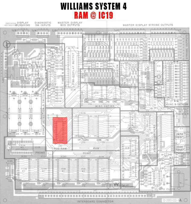
IC 17 definitely exists somewhere. It holds half of the flipper rom. A nice place to find assembly drawings is pinitech as he has them to highlite the 5101 locations
https://www.pinitech.com/product_images/ram_locations/ramloc_williamssys4.jpg
Quoted from johnboy1313:Am I correct that it doesn't look like that diode is even needed? On page 15 of the manual, it shows that the bottom set of switches isn't used.
https://www.ipdb.org/files/871/Williams_1978_Flash_Manual_March_1979_no_schematics.pdf
Looks like it, I bet someone needed a diode and stole it from there because it's not used.
I have always been hamstrung by non booting mpus. Thanks in part to this adapter I've been able to get 3 working. 1 wasn't switching the reset line high and needed a transistor replaced. 1 had a solder bridge under the ram socket. The other was this board. This 01a test is great for this.
You're currently viewing posts by Pinsider cheddar.
Click here to go back to viewing the entire thread.
Wanna join the discussion? Please sign in to reply to this topic.

Great to see you're enjoying Pinside! Did you know Pinside is able to run without any 3rd-party banners or ads, thanks to the support from our visitors? Please consider a donation to Pinside and get anext to your username to show for it! Or better yet, subscribe to Pinside+!

This page was printed from https://pinside.com/pinball/forum/topic/new-pincoder-adapter?tu=cheddar and we tried optimising it for printing. Some page elements may have been deliberately hidden.
Scan the QR code on the left to jump to the URL this document was printed from.