(Topic ID: 134886)

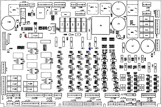
JM - Check fuse F115 F116 J112 Opto

By playboywillis

8 years ago


Topic Heartbeat

Topic Stats

  • 100 posts
  • 7 Pinsiders participating
  • Latest reply 8 years ago by mot
  • Topic is favorited by 1 Pinsider

You

Linked Games

Topic Gallery

View topic image gallery

J212_WPC-s_1left.jpg
IMG_0206.jpg
misplugged-1.jpg
facepalm.jpg
image2.jpg
image1.jpg
wpc-s-cpu-board.jpg
JohnnyNEW.jpg
jm-switch-matrix.png
image1.jpg
C__Data_Users_DefApps_AppData_INTERNETEXPLORER_Temp_Saved_Images_images.jpg
C__Data_Users_DefApps_AppData_INTERNETEXPLORER_Temp_Saved_Images_wpc.gif
jm-cpu-connectors.png
There are 100 posts in this topic. You are on page 1 of 2.
#1 8 years ago

Hi, I've been trying to troubleshoot this in the JM thread but am bringing it to its own topic in hope of assistance. Warning - this is my first real work inside a machine.

Have the error in the title and was using this as a guide: http://www.pinwiki.com/wiki/index.php?title=Williams_WPC#Check_fuses_F114_and_F115_message I complete steps 1-11 and it all passes. I tried step 1 after these steps and get fluctuations from 1 to around 3. Not sure if this is good because there is activity, or bad because it's not the right activity.

I have reseated all ribbon cables, all connectors basically on the power board and sound board. I replaced fuses F115 and F116. All of the LEDs on the power board are on and all TPs come back with the correct voltage. The opto board under the playfield has an LED light that is on, and I have reseated all connections.

There are other errors. Upon startup, the drop target fires quite a few times, and I hear the hand clicking. There are errors for both of these when entering the test menu. These are both related to J107, and I am getting the correct voltage from those pins. I'm unsure if these errors are related to the fuse issue.

I have gone off of a lot of these Check F115 F116 threads that I could find on all forums, but the big difference between them and mine is that all of my board LEDs are working and none of my fuses appear to be blown. I have also tested the fuse holders for F115 and F116 and it all appears normal.

Does anyone have an idea where to go from here? Thanks

#2 8 years ago

I don't know if it helps, but in the switch edge test, some switches work and some don't.

#3 8 years ago

I was wrong, TP7 is not getting the correct voltage. Looking into it.

Nevermind. Still learning the DMM.

#4 8 years ago

Im not a board expert but there is a rom chip on cpu that my have been damaged. Any history? Did the game work and then stop? Any chance you were working on it with power on?

#5 8 years ago

It worked before transporting. It's possible I might have hooked it up yesterday missing a connector or two, but have not been working with the power on. If something was damaged, I was just looking for a point in the right direction to test it.

#6 8 years ago

Def start with voltages at all test points

#7 8 years ago

All test points are correct. J112 J116 J117 & J118 are correct.

#8 8 years ago

any chance a ribbon cable backwards? I would focus on connectors/ribbon cables on CPU

you checked all fuses out of the holders? with DMM?

#9 8 years ago

I only checked F115 and F116 out of holders. Should I do them all separately or at the same time?

Ribbon cables are correct.

I was just reading a guide and this is stated: Test for AC voltage at J101 pins 4 and 7 (or J129 pins 4 and 7 on WPC-95). A reading of 13 to 18 volts AC should be seen. This is the AC voltage coming from the
transformer. If no voltage here, check the Molex connectors around the transformer and at the power driver board.

I think this means continuity testing, or buzz. I also assume this means testing 4 and 5 together and 6 and 7 together. When I do this with the continuity setting, it flashes a high number and falls back down to 0. I'd guess that means that there's an issue with the transformer, but all connections seem tight. So tight in fact, I can't take them apart by hand.

Does this mean anything to you?

#10 8 years ago

Last question for the night. When I test a fuse holder with the fuse out, what should I be seeing? Should it be the desired voltage on one side and a smaller voltage on the other, or should it be the desired voltage on both sides?

For example, should F115 read 12V on the right and around 1-3V on the left, or should it read 12V on both sides?

I appreciate all the help, but I've been at this for 7 hours straight for the second night in a row. Have to pick it back up tomorrow.

Thanks again

#11 8 years ago

About your question in post #9 concerning J101. The fact you can enter the test-menu (post #1) means that 5V and 12Vreg is present and J101 is fine.

Then, in post #10:

Quoted from playboywillis:

should F115 read 12V on the right and around 1-3V on the left, or should it read 12V on both sides?

would suggest 12Vreg. is no longer working. Fuse on the left side should be 12V as well.

Can you check connectors on both ball-trough boards ? or check those opto's in testmenu switch-edges.

#12 8 years ago

I check fuses using continuity. Lead on each side and listen for tone

#13 8 years ago
Quoted from zaza:

would suggest 12Vreg. is no longer working. Fuse on the left side should be 12V as well.

That makes sense. I was thinking at first that the fuse completes the circuit, but it sounds like the circuit should already be there and the fuse is just a safety between the circuit?

Quoted from zaza:

Can you check connectors on both ball-trough boards ? or check those opto's in testmenu switch-edges.

I'll have to check this when I get home.

Quoted from billsfanmd:

I check fuses using continuity. Lead on each side and listen for tone

I have a cheap DMM that doesn't actually make a tone. Is there a specific number I should be looking for?

#14 8 years ago
Quoted from playboywillis:

I don't know if it helps, but in the switch edge test, some switches work and some don't.

This is the core of the problem. The error message you're seeing is displayed because there are problems detected with the switch matrix.

Which switches on the game work and don't work?
Is switch 24 closed?
Do any of the optos work? Are they open or closed?
Do you get the error message if you disconnect the connectors from the opto boards under the playfield?

#15 8 years ago
Quoted from mot:

Which switches on the game work and don't work?

I can't give you all of them at the moment, but I can tell you that the switches in the coin door are seen, if I hold a flipper up it registers, but pushing the inlanes and outlanes down, for example, doesn't register.

Quoted from mot:

Is switch 24 closed?

Switch 24 is open, which I believe is the root cause of the "Check Fuse" error.

Quoted from mot:

Do any of the optos work? Are they open or closed?

I'd have to check this when I get home. I don't think I did any opto tests.

Quoted from mot:

Do you get the error message if you disconnect the connectors from the opto boards under the playfield?

I'll also have to try this when I get home. I did reseat all of the opto board connectors under the playfield, but never checked them in the test menu.

#16 8 years ago

Oh shit, I think I've been reading this wrong. When you guys say test the fuse out of the holder, you mean test the actual fuse itself? I thought everyone was saying to test the fuse holder on the board with no fuse in it.

If that's the case, Fuse 115 and 116 are definitely good. I will check all of the other fuses tonight, and go buy some new ones for the other slots.

#17 8 years ago
Quoted from playboywillis:

Switch 24 is open, which I believe is the root cause of the "Check Fuse" error.

That's a problem.

Do you have any signs of battery leakage on the CPU board? The switch matrix components are right under the battery and can be ruined by corrosion. You can test if the problem is on the CPU board by disconnecting the switch matrix connectors and using a wire to short column pins to row pins in switch test mode.

http://www.pinwiki.com/wiki/index.php?title=Williams_WPC#Switch_Matrix_Problems

#18 8 years ago

No battery leakage. The game was working 100% before I moved it, so I really don't think it would be corrosion.

However, I'll try any fix I can find.

#19 8 years ago

I'll check that out. I've got a weird one for you. On JM, 212, 205, 206, 208 and 209 all have multiple wires going to them. When we were taking the head off of this one, there was a stray wire electrical taped to a group of wires, but I couldn't see any exposed wires, so it seemed like this wire was just taped to get it out of the way.

The game was working fine without this wire. I've found out that wire is supposed to be the only wire connected to J207 and it's described like this in the menu: to cabinet switches

I would think this would make a difference but the game was working without it, unless it was hacked into a wire and I just couldn't see an exposed wire. I've checked multiple wire groups but could not find the sticky electrical tape residue where it was originally taped.

#20 8 years ago

Also, what was suggested in another thread was "Run a jumper lead from J206-2 to J208-4 and see if it goes away. The jumper would simulate the closure of switch #24." I'll buy a jumper after work today too, if y'all think this would help rule things out.

#21 8 years ago

Only fuse that was bad was F104. Replaced that but didn't notice a change.

Now I looked at the ball trough boards and none of the LEDs are lit. The wires that are sodered to it are getting around 72V, but yeah, the LEDs aren't lit up.

#22 8 years ago

Can you make a picture of the trough boards with the wires that are 72 Volt ? Although the LED's are infra-red and not visible for human eyes, this doesn't sound correct.

#23 8 years ago

When I Had this problem on my WPC-S system it was a blown LM339 chip on the opto board.

#24 8 years ago

yeah im thinking opto board issue too.

#25 8 years ago
Quoted from zaza:

Can you make a picture of the trough boards with the wires that are 72 Volt ? Although the LED's are infra-red and not visible for human eyes, this doesn't sound correct.

I was wrong. They're not actually attached to the board, but to the coil that pops the balls out.

Quoted from TheLaw:

When I this problem on my WPC-S system it was a blown LM339 chip on the opto board.

Is there a way to test this with a DMM, or do I need to keep ruling other things out?

#26 8 years ago

When I bought a new one I bought a handful, because they aren't that expensive, and I never wanna go through the shitshow that was finding the problem. Sooo annoying.

#27 8 years ago

Hehe, well I've got about 15 hours in and have tried a lot of stuff. Game was 100% before it rode in the car (and I hooked everything back up).

Going to try to test the switch matrix now.

#28 8 years ago

If the CPU board is good, you can disconnect the opto board to rule it out.

#29 8 years ago
Quoted from playboywillis:

Is there a way to test this with a DMM, or do I need to keep ruling other things out?

See below. If it were me, I would order some online and then go aboot the fixing you're going to be doing anyway, and if you need them, you have them. It could be a ton of things...but whenever I hear "drop targets firing repeatedly" it make me think opto issues.

-What Goes Wrong?
The biggest problem for these boards is switch matrix shorts. If any of the power lines hits the switch matrix, it can easily destroy the LM339 and possibly its output diode. This issue will manifest as a ground short on one or more rows. It can be tested by removing the switch matrix connector. If the problem goes away, the associated LM339 and possibly its diode need to be replaced. -

http://www.pinwiki.com/wiki/index.php?title=Williams_WPC#Miscellaneous_WPC_Boards

EDIT: That's if you're sure the 12v power is fine on the Power board

#30 8 years ago

Just did the testing from this link, http://www.pinwiki.com/wiki/index.php?title=Williams_WPC#Switch_Matrix_Problems and it all checks out.

I disconnected J106 J107 J108 J109 and error remains. Ran a jumper from from J107-2 to J109-4, closing switch 24, and the error went away.

#31 8 years ago

Also, I'm guessing Lm339 needs to be soldered on, hehe.

I can't solder.

#32 8 years ago

Hmm...got anyone near you with a similar machine you could hook your opto board up to and test?

#33 8 years ago

Its' possible. Shit man.

By the way, I appreciate all the help you guys are giving me.

#34 8 years ago

Unless someone can tell us how to test a LM339 chip that's installed, you're gonna have to get to someone close...ANYONE?
Such a bitch of a problem this one, I hated it.

#35 8 years ago

Honestly dude, if it's not that I wouldn't know what to do. Feel like I've tested everything in this thing.

#36 8 years ago

Unfortunately, LM339s can't be tested in circuit.
I've fixed quite a few of these. LMK if I can help.
--
Chris Hibler - CARGPB #31
http://www.Team-EM.com
http://webpages.charter.net/chibler/Pinball/index.htm
ttp://www.PinWiki.com - The Place togo fr Pinball Repair Info

#37 8 years ago
Quoted from playboywillis:

Also, I'm guessing Lm339 needs to be soldered on, hehe.
I can't solder.

If you can't solder there are alot of people on here that do board work, ask for some help I am sure someone would love to do the repair. PM me if u want names. I've had your error before and it was due tina bad edge connected were the +12v was coming in. Make sure all your wires are properly pushed in Molex connectors.

#38 8 years ago

So switch 24 shows as open. That's problem number one in my opinion. Let's look at how switch 24 works. (I'm referencing the manual on IPDB).

On the CPU Board:
J212-2, Green-Red, switch col. 2, to Coin Door Board J3-2
J212-8, White-Yellow, switch row 4, to Coin Door Board J3-6

On the Coin Door Interface Board
J3-2 is connected directly to J3-6 via diode D2

It's that simple. That's why I think you should start here. Forget about the playfield wiring and the opto boards. You might even disconnect all of the following to simplify everything:
J205 (dedicated switches to coin door)
J206 (playfield switch rows)
J207 (cabinet switch columns)
J208 (playfield switch columns)
J209 (cabinet switch rows)

#39 8 years ago
Quoted from playboywillis:

When we were taking the head off of this one

I didn't catch this the first time. You took the head off. That's not really a problem, but you've just got something wrong somewhere somehow, and I still think it's going to be an easy fix!

Quoted from playboywillis:

, there was a stray wire electrical taped to a group of wires, but I couldn't see any exposed wires, so it seemed like this wire was just taped to get it out of the way.
The game was working fine without this wire. I've found out that wire is supposed to be the only wire connected to J207 and it's described like this in the menu: to cabinet switches

That lone wire on J207 is switch column six. If you look at the switch matrix, you'll see that it's for the extra flipper buttons to move the hand back and forth. Switches 67 and 68. Those won't work without that wire...

#40 8 years ago

Problem is that I was the one hooking the head back up. I'm also the one who told him what to mark that side as, the security board.

I've been thinking back and I'm pretty sure I mixed up two of the connectors between j106-j109, specifically, I think either mixed up 08 and 09, or 06 and 07.

Probably blew up something.

#41 8 years ago

Oh and the last thing I did tonight was hook that wire up to 207 and it didn't change anything

#42 8 years ago
Quoted from ChrisHibler:

Unfortunately, LM339s can't be tested in circuit.

Typical.

#43 8 years ago

My guess is loose line on the right side coming on that J101 connector. Optos all run on the 12volts so no +12 no optos. Amended J101. I was going off memory just checked the manual.

#44 8 years ago
Quoted from playboywillis:

I've been thinking back and I'm pretty sure I mixed up two of the connectors between j106-j109, specifically, I think either mixed up 08 and 09, or 06 and 07.
Probably blew up something.

I don't think mis-connecting any of those small switch line connectors could cause any damage. If you can get switch 24 to close by using a wire on the board, you can get the coin door interface to do it's job on switch 24.

I still say figure out switch 24 before you go any further. Use page 3-25 of the manual to verify the colors of the wires at each connector.

jm-cpu-connectors.PNGjm-cpu-connectors.PNG

#45 8 years ago

Awesome guys. I'll give the J101 connector a look.

Mot that board is now correct. If I hooked them up wrong it was only for a few seconds. I feel like that page you linked is burned into my eyes.

Would you have any idea what to look for on the coin board? aside from reseating connectors and testing voltages I'm pretty illiterate at this point in time.

#47 8 years ago

Yeah, that guide always ends with replacing U20 if you can't figure out what's going on.

#48 8 years ago

This thread is all over the place.
What exactly is the problem now?
Switch 24 isn't being seen?
--
Chris Hibler - CARGPB #31
http://www.Team-EM.com
http://webpages.charter.net/chibler/Pinball/index.htm
http://www.PinWiki.com - The Place to go for Pinball Repair Info

#49 8 years ago

Something like that. Switch 24 is open when it should be closed.

There's a couple guides out there, most point to a BR, U20, LM339, or an easy fix. I was hoping for the easy fix one.

#50 8 years ago

I agree with Chris. Starting at beginning of this thread your symptoms like the popping are optos firing due to a lack of 12v. That fuse 114-115 error can be caused by lack of 12v. Always start at power. Confirm your 12v first and go from there.

Promoted items from Pinside Marketplace and Pinside Shops!
3,000 (OBO)
Machine - For Sale
West Chester, PA
From: $ 9.99
Eproms
Matt's Basement Arcade
 
€ 150.00
Cabinet - Decals
Pin-Decals
 
$ 18.95
Eproms
Pinballrom
 
$ 11.95
Playfield - Toys/Add-ons
ULEKstore
 
$ 22.50
Electronics
bdash's bits
 
$ 63.95
Eproms
Pinballrom
 
From: $ 399.95
Lighting - Led
Pin Stadium Pinball Mods
 
$ 29.00
From: $ 27.00
Boards
KAHR.US Circuits
 
5,000
Machine - For Sale
Oakley, CA
$ 22.50
$ 1.00
Pinball Machine
Pinball Alley
 
$ 16.50
Lighting - Led
Lermods
 
$ 37.50
4,500
Machine - For Sale
New Castle, CO
3,500
Machine - For Sale
Merritt Island, FL
From: $ 9.99
Eproms
Matt's Basement Arcade
 
$ 5.00
Playfield - Protection
UpKick Pinball
 
There are 100 posts in this topic. You are on page 1 of 2.

Reply

Wanna join the discussion? Please sign in to reply to this topic.

Hey there! Welcome to Pinside!

Donate to Pinside

Great to see you're enjoying Pinside! Did you know Pinside is able to run without any 3rd-party banners or ads, thanks to the support from our visitors? Please consider a donation to Pinside and get anext to your username to show for it! Or better yet, subscribe to Pinside+!


This page was printed from https://pinside.com/pinball/forum/topic/jm-check-fuse-f115-f116-j112-opto and we tried optimising it for printing. Some page elements may have been deliberately hidden.

Scan the QR code on the left to jump to the URL this document was printed from.