(Topic ID: 239476)

Haunted House resto - PLUS Multiball and speach!

By SunKing

5 years ago


Topic Heartbeat

Topic Stats

  • 115 posts
  • 25 Pinsiders participating
  • Latest reply 2 years ago by ludikris
  • Topic is favorited by 35 Pinsiders

You

Linked Games

Topic Gallery

View topic image gallery

Black-Hole-Pinball-Machine9 (resized).jpg
AC4E28D6-E9E5-4716-97FD-41ACE9F1A5A2 (resized).jpeg
IMG_7571 (resized).JPG
IMG_7537 (resized).JPG
IMG_7536 (resized).JPG
IMG_7531 (resized).JPG
IMG_7521 (resized).JPG
IMG_7518 (resized).JPG
IMG_7516 (resized).JPG
IMG_7515 (resized).JPG
IMG_7513 (resized).JPG
IMG_7508[1] (resized).JPG
IMG_7511[1] (resized).JPG
IMG_7499 (resized).JPG
IMG_7501 (resized).JPG
IMG_7493 (resized).JPG
There are 115 posts in this topic. You are on page 3 of 3.
#101 3 years ago

Next up is to install the ball gate assembly. Measurements on this are just general... you have to monkey with the position to get it just right, so giving a hard measurement probably doesn't help a lot. But I installed mine 2" from the tip of the ball holder triangle, to the end of the big ball guide. Again you'll have to monkey with it. I always installed stuff with just one screw and made adjustments. After i got it where i wanted, only then added the other screws to lock it in place.

http://www.pinrepair.com/sys80/hhmb_lower13.jpg

http://www.pinrepair.com/sys80/hhmb_lower14.jpg

http://www.pinrepair.com/sys80/hhmb_lower15.jpg

#102 3 years ago

Very helpful write-up. Thank you Clay!!

#103 3 years ago

There''s one more step on the Haunted House multiball lower playfield. And that's the ball guide. It was removed previously, but we need to re-purpose it here. It requires some new holes for the ball guide. Since the wire form is about .095" thick, a 3/32" drill bit works well for this.

http://www.pinrepair.com/sys80/hhmb_lower16.jpg

http://www.pinrepair.com/sys80/hhmb_lower17.jpg

http://www.pinrepair.com/sys80/hhmb_lower18.jpg

http://www.pinrepair.com/sys80/hhmb_lower19.jpg

#104 3 years ago

Now that the ball guides are in place, need to finish up the wiring. Pascal's notes on this are difficult to follow. Add to that, I used a micro switch (instead of leaf switch), so my process is a bit different. Also I have no problem drilling holes in things, where Pascal is much more conservative about doing that. (I figure this thing is highly modified anyway, so what's the difference?) For example I drilled a 1/4" hole for my wires going to the ball release coil.

http://www.pinrepair.com/sys80/hhmb_lower20.jpg

#105 3 years ago

Under the playfield is where all the fun happens. You need to add a fuse with a 1amp S.B. fuse for the ball release coil. Pascal correctly identifies the pull up resistor as a great place to get 24 vdc for coil power. Also need to run a wire from the diode block to the micro switch. Also need to add a wire to the 10pt switch for the sling shot. This wire will also go to the added micro switch.

http://www.pinrepair.com/sys80/hhmb_lower21.jpg

http://www.pinrepair.com/sys80/hhmb_lower22.jpg

#106 3 years ago

And then of course the wires go to the mirco switch. The switch originally came with a 1n4001 diode. You can not use that diode on a system80! So replace that diode with a 1n270 diode. These diodes are strange glass animals, and the red is the 'band'. It must be oriented correctly on the switch. And the wires connected properly, or it just won't work!

http://www.pinrepair.com/sys80/hhmb_lower23.jpg

#107 3 years ago

Last up is a modification that Pascal notes in his document. Basically the red "Special when Lit" light blinks when a ball can be locked on the lower playfield for multi ball. He came up with a system to change the GI lamps to CPU controlled lamps, making it more obvious to the player that the ball needs to get locked on the lower playfield. Well i say Bullshite to that! The lower playfield needs all the GI lights it can get, so taking some away doesn't seem like a good idea. Instead I add two new lights.

Drilled two .450" holes (yes that's the proper size, but i guess you could use 1/2") and mounted two new green LED light bulbs and sockets. I used green bright LED lights (in Williams world, green means LOCK!) These need to be bright, because they are under the plastic, and you want the user to see them easily.

http://www.pinrepair.com/sys80/hhmb_lower24.jpg

#108 3 years ago

Then last, you need to tie the two new added LED bulbs to the existing red "special when lit" light.

I would say it's important to use an LED bulb for the red "special when lit" light and the green added lights. Why you ask? because these CPU controlled lights are sunk by an MPS transistor, which aren't designed to sink a lot of load. Using LEDs is great, because you can probably put 10 LED bulb per MPS transistor without any harm! Pascal's document is pretty old, and he was using standard #44 light bulbs. Upgrade to LEDs! The game needs it, at least on the lower playfield. You can thank me later...

Anyway, the CPU controlled lights have a 6 vdc buss that you need to run to the two new sockets. That's the wire that goes to the mounting bracket of the "special when lit" socket. On the "tit" of the "special when lit" socket, run two wires to the "tit" of the added sockets. That's all you have to do, and when the lower lock is available for a ball, you get a nice blinking action from those three LEDs.

http://www.pinrepair.com/sys80/hhmb_lower25.jpg

#109 3 years ago

HAUNTED HOUSE MULTIBALL MOD.
======================
MAIN PLAYFIELD MODIFICATIONS.

Pascal's descriptions in his document are pretty good for the main playfield. But thought I should add some pictures as it may help. Basically though you are stealing ball trought parts from a Black Hole or Volcano or Mars God of War, and adapting those ball trough parts to the Haunted House. It's pretty easy to do (especially if you have a Black Hole sitting right there!) The only bad part is cutting the playfield for the new added switch. Adding the ball release coil is pretty easy. Just go slow and do it after the trough is in place, so you can get the alignment nice. And again i choose to use a micro switch, so my procedure is a bit different than Pascal's procedure. I did the switch slot last, which seems to be the right way to go. And don't forget to add the dual plastic post where the ball drops into the outhole. that is required to slow the ball down, and prevent two balls from getting in the outhole at the same time.

http://www.pinrepair.com/sys80/hhmb_main01.jpg

http://www.pinrepair.com/sys80/hhmb_main02.jpg

http://www.pinrepair.com/sys80/hhmb_main03.jpg

http://www.pinrepair.com/sys80/hhmb_main04.jpg

#110 3 years ago

Great pictures. Thanks again!!

#111 3 years ago

Like Pascal documented on the lower playfield, he also wanted to make the right side ball#2 lock more obvious. So to that end, Pascal re-purposed some GI lights to the extra ball light. This make the lock more obvious, but at the expense of GI lights. As with the lower playfield, me thinks this is a bad idea.

So what I did was to add two new lights, that will tie to the extra ball/lock#2 light. Again I think this is a better approach. And again, using LED lamps is ideal here, as it puts less load on the driving lamp MPS transistor. In this case I added two lights (see picture below), by drilling two new holes (.450" diameter, or 1/2" in a pinch) and adding two new lamp sockets. It's better to use a .450" drill bit here, as it's really tight. Used red LED lamps here (works well, looks decent.) Just tied the new socket wires to the Extra ball lamp socket (just like on the lower playfield.)

Another good idea that Pascal suggested was to remove the plastic post on the slingshot, and replace it with a thinner metal post. And move the ball guide north a bit. This opens up the extra ball/lock#2 opening. Otherwise it's really a hard shot to hit (mostly a luck shot). It helps a lot for locking the ball, you can *almost* hit it with the flipper by doing this.

http://www.pinrepair.com/sys80/hhmb_main05.jpg

http://www.pinrepair.com/sys80/hhmb_main06.jpg

#112 3 years ago

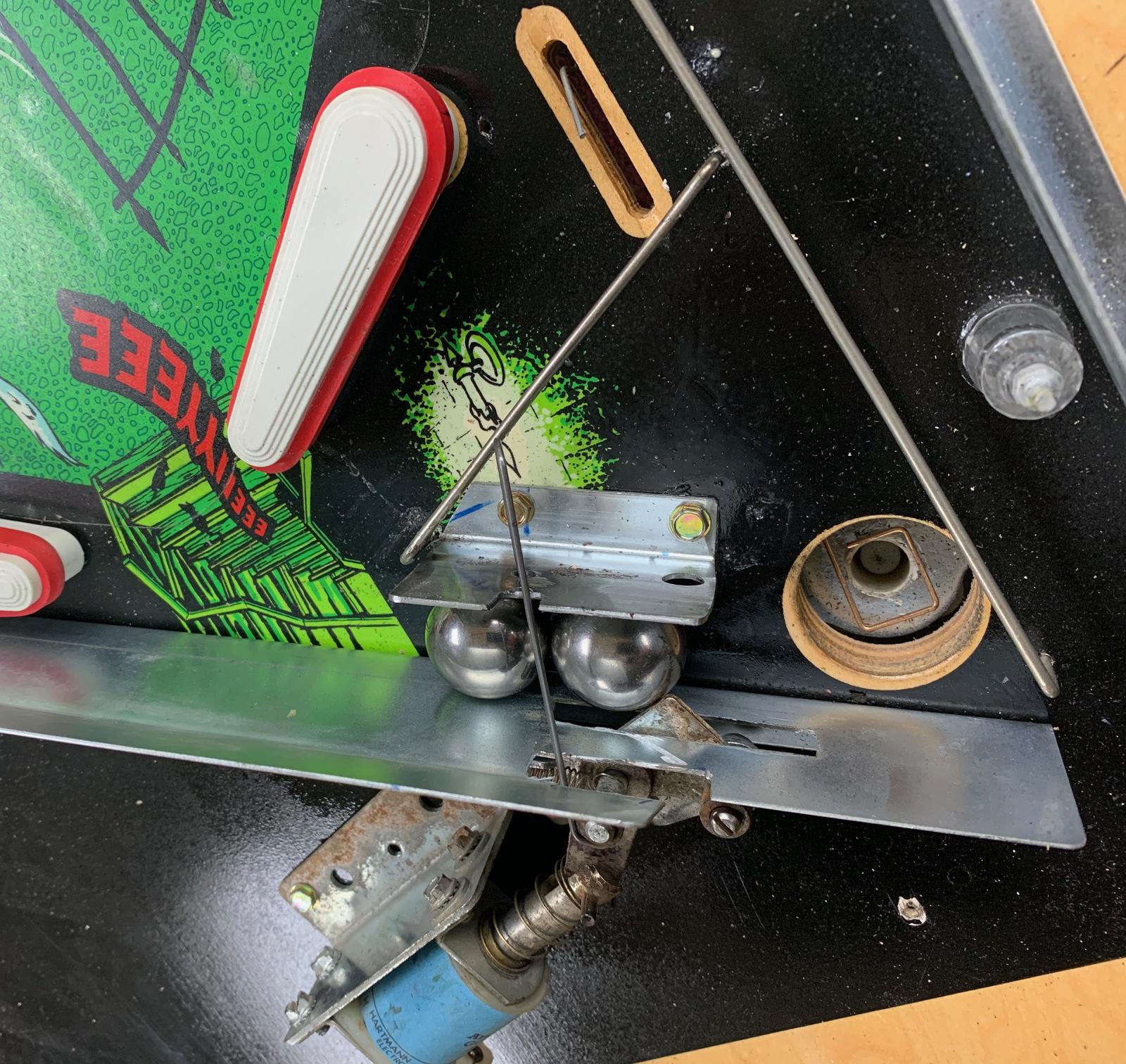
There's one last thing to do, one last modification. It has to do with the flippers. Basically during Haunted House multiball, you need *all* the flippers to work at once. Because when the U relay pulls in (ball on the lower playfield), it turns *off* the main playfield flippers.

I argued with Pascal on this point too. He insisted that he needed to add another relay, the Z relay, to make this all work. I told him he was freaking nuts to do it this way...

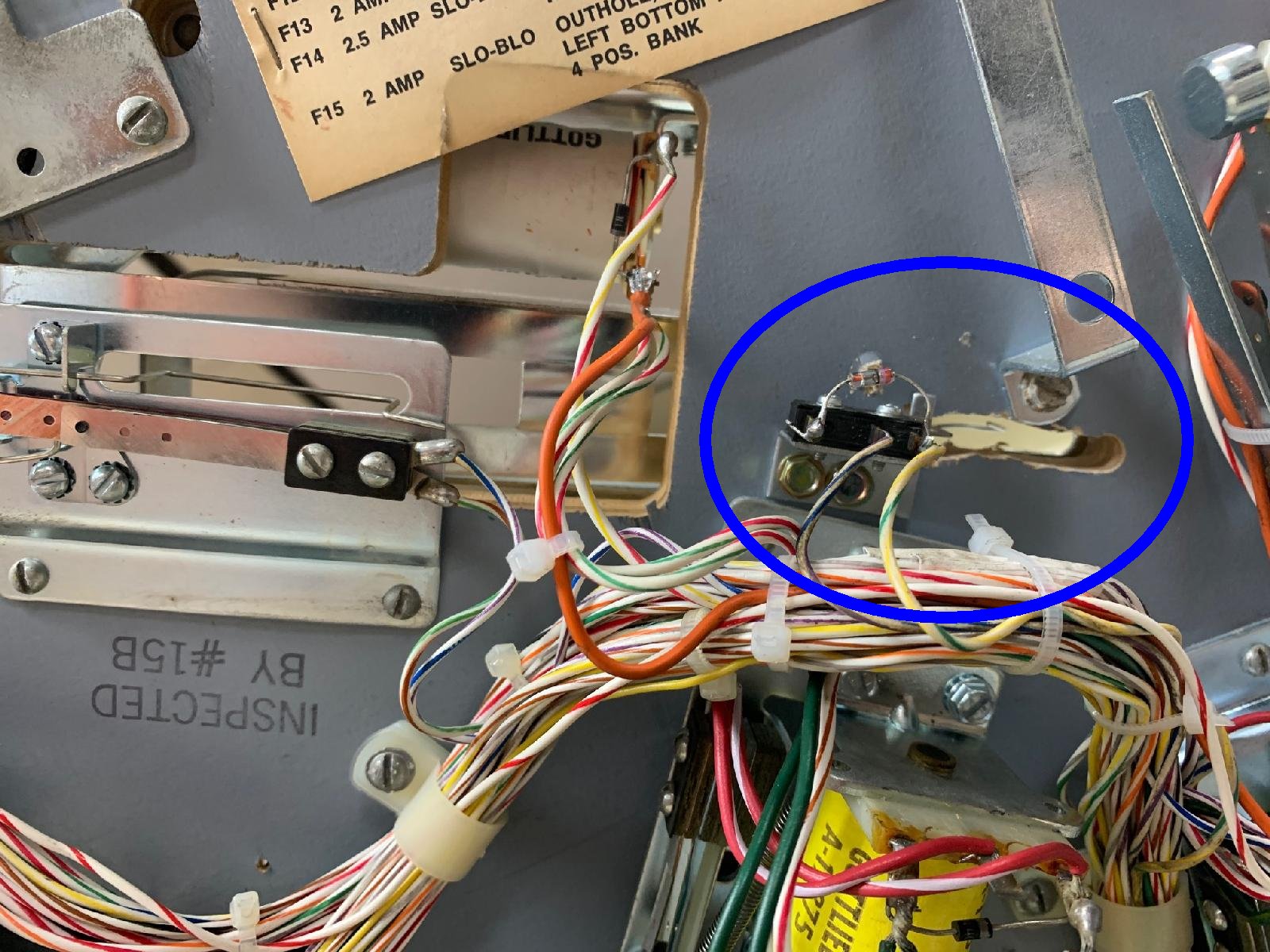
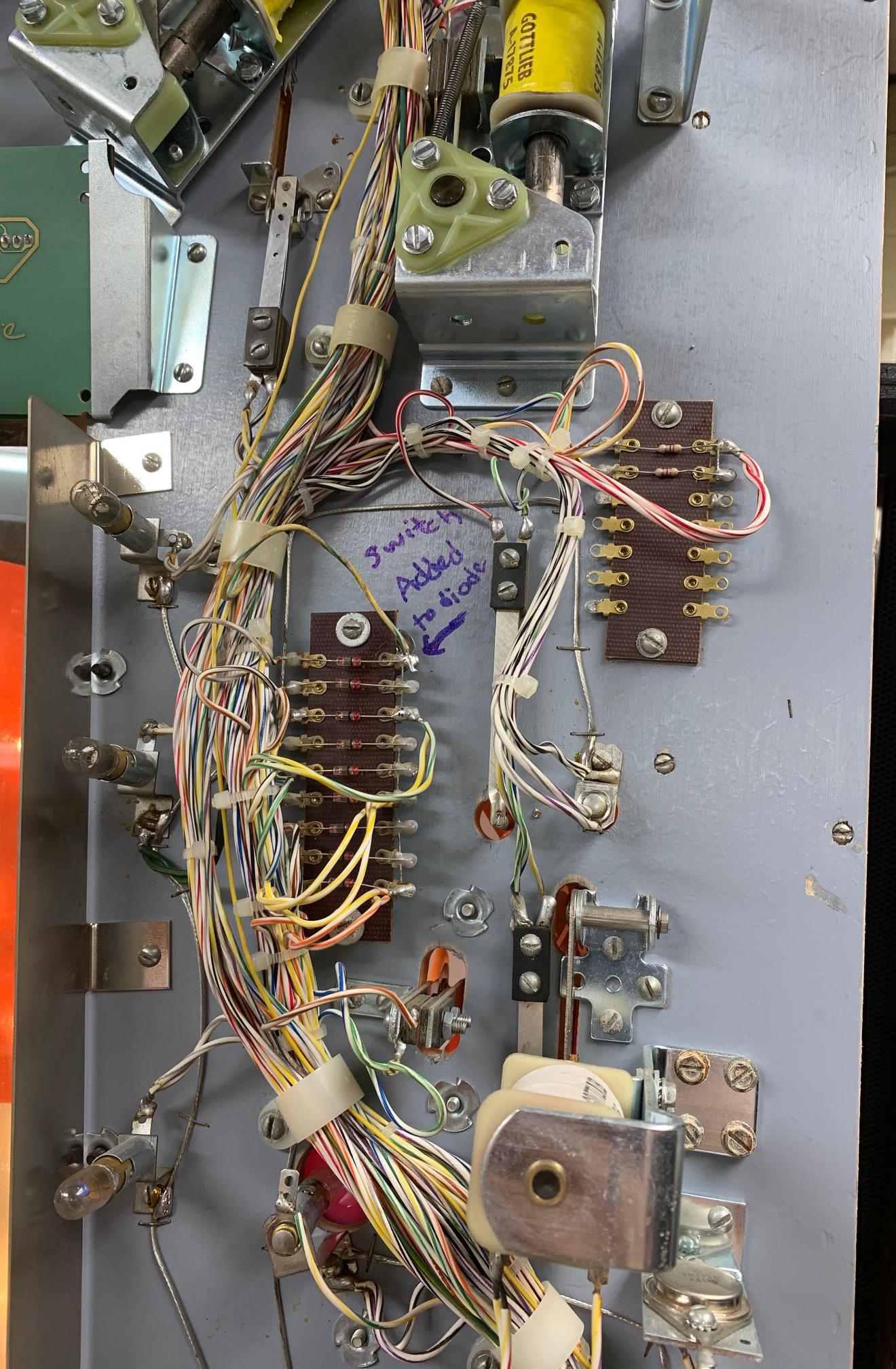
And if you read Pascal's instructions on this, it's freaking complicated what he wants he wants to do! ...Add a Z relay and modify the existing relays. MY GAWD WHAT A CLUSTER SCREW. I'm sorry, I just can't do it. I mean i started to do it... but then thought, this is freaking crazy. I read Pascal's instructions 10 times, and just thought, "this is freaking nuts"... I started to buy into his crap, and took the 3 relay bank, and modified mine for a 4th "Z" relay...

http://www.pinrepair.com/sys80/hhmb_main07.jpg

What mess! I said to myself, "self, this is NUTS, there has to be a better way!" And sure enough, best I can tell, there IS a better way...

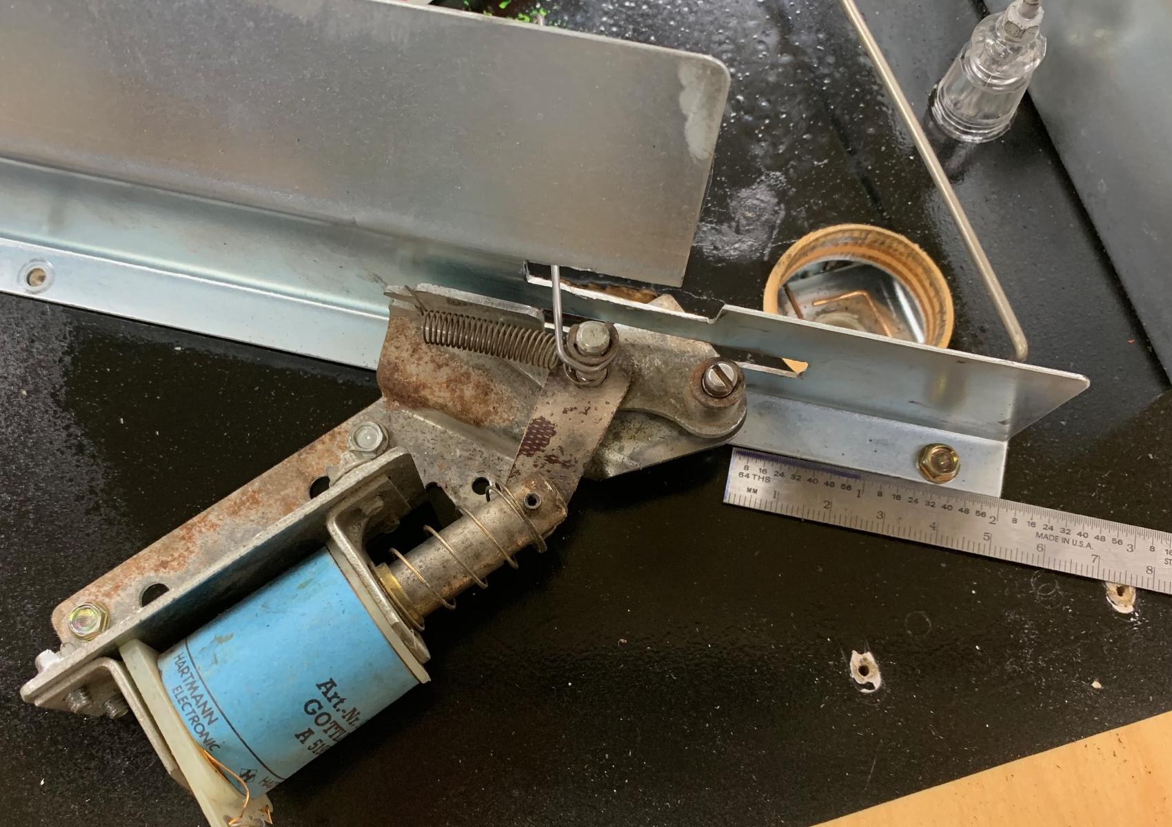
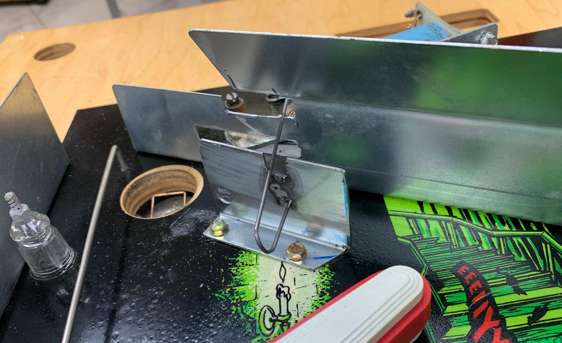
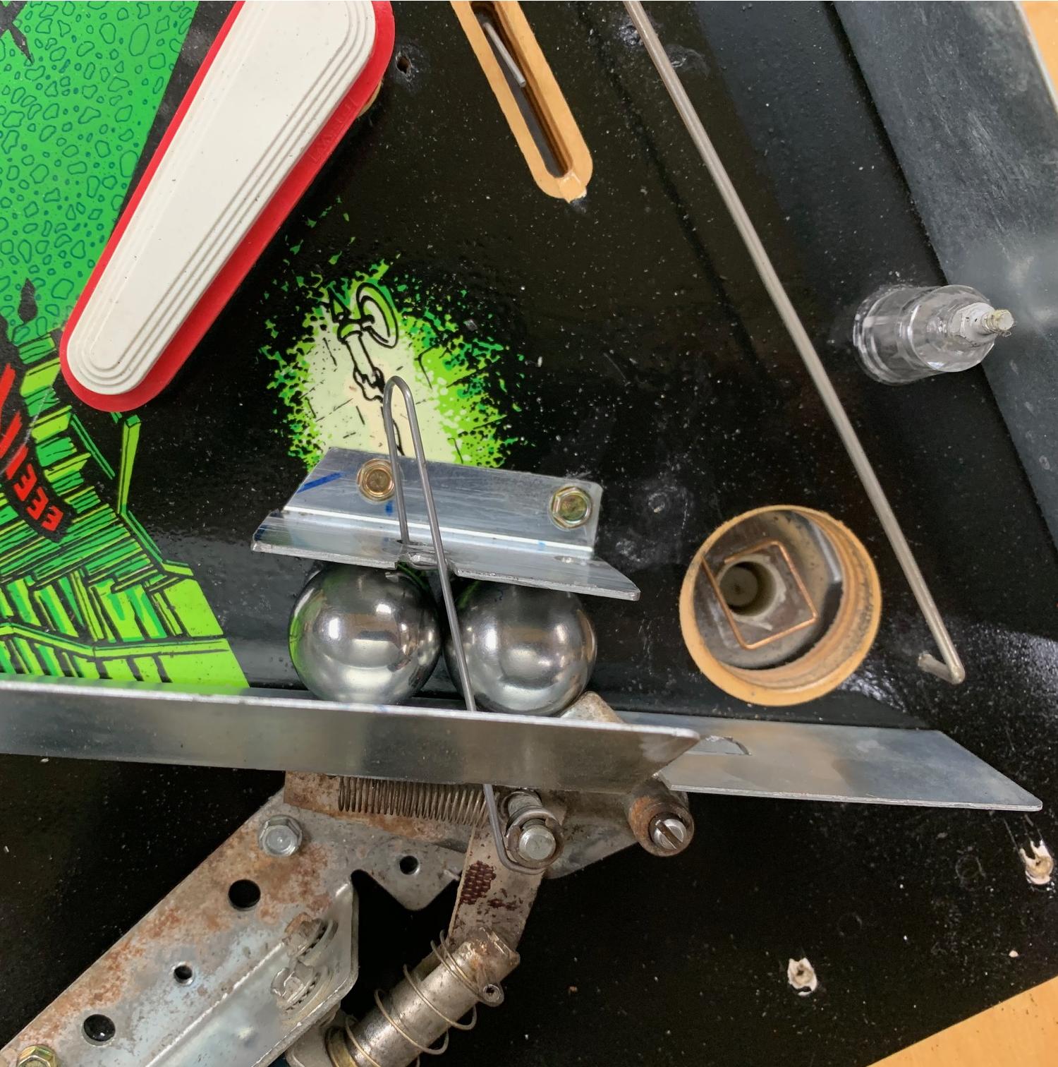
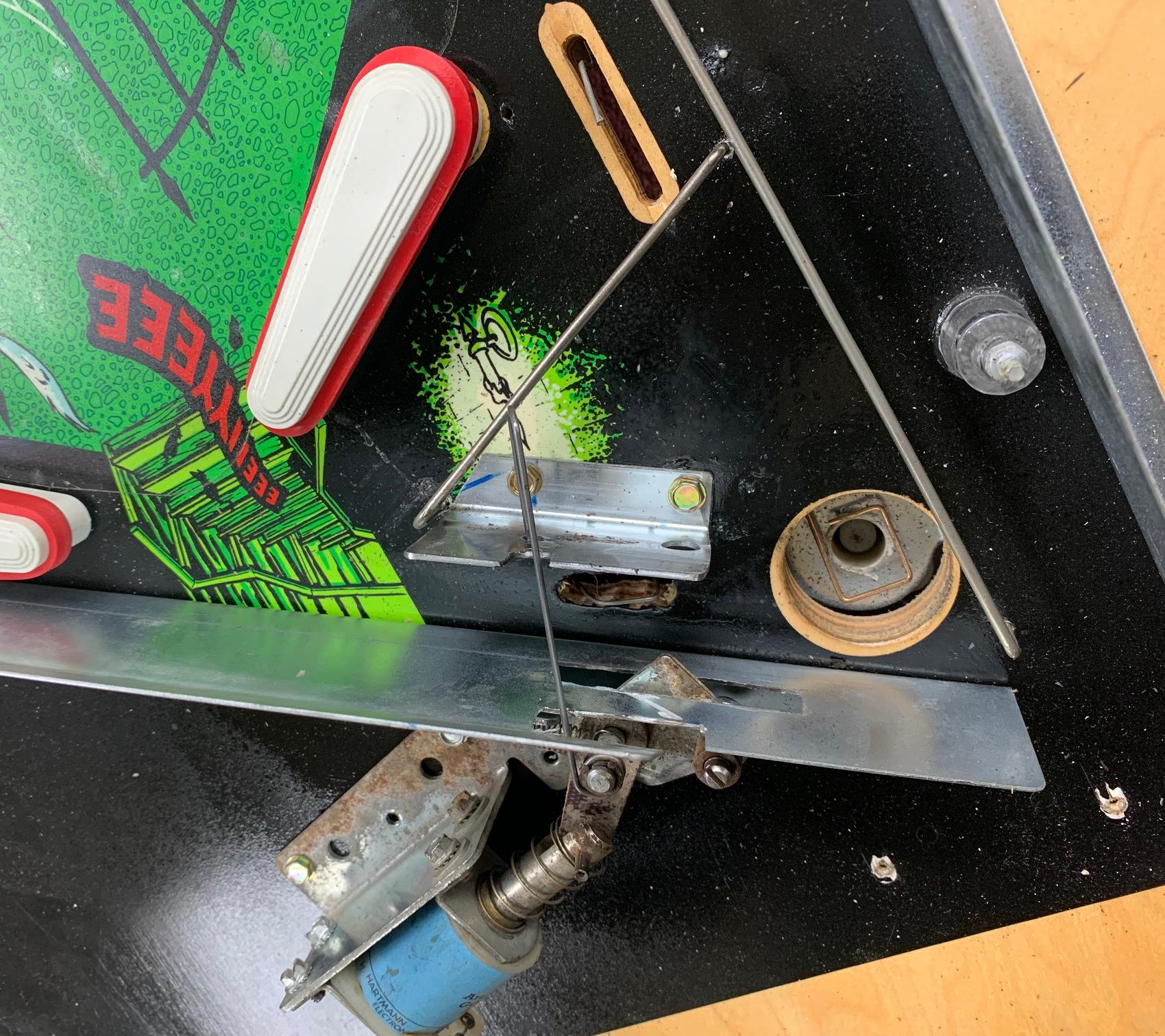
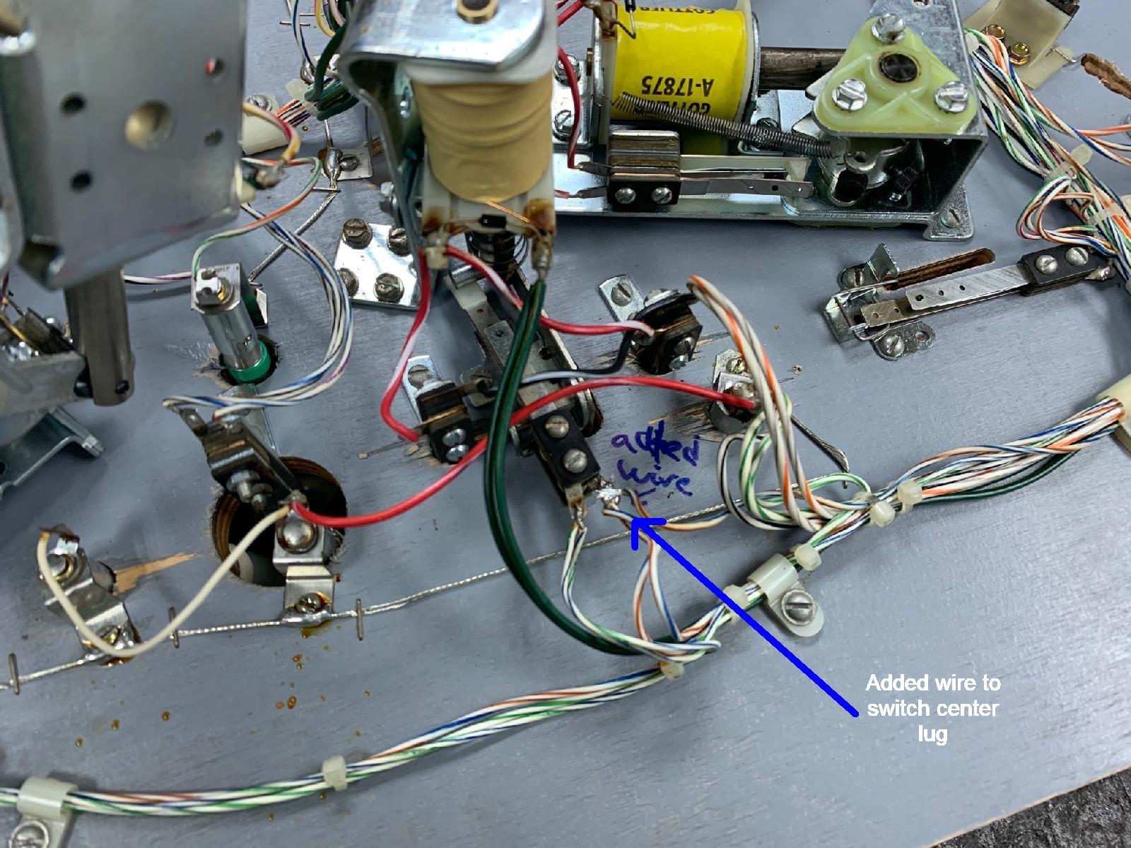
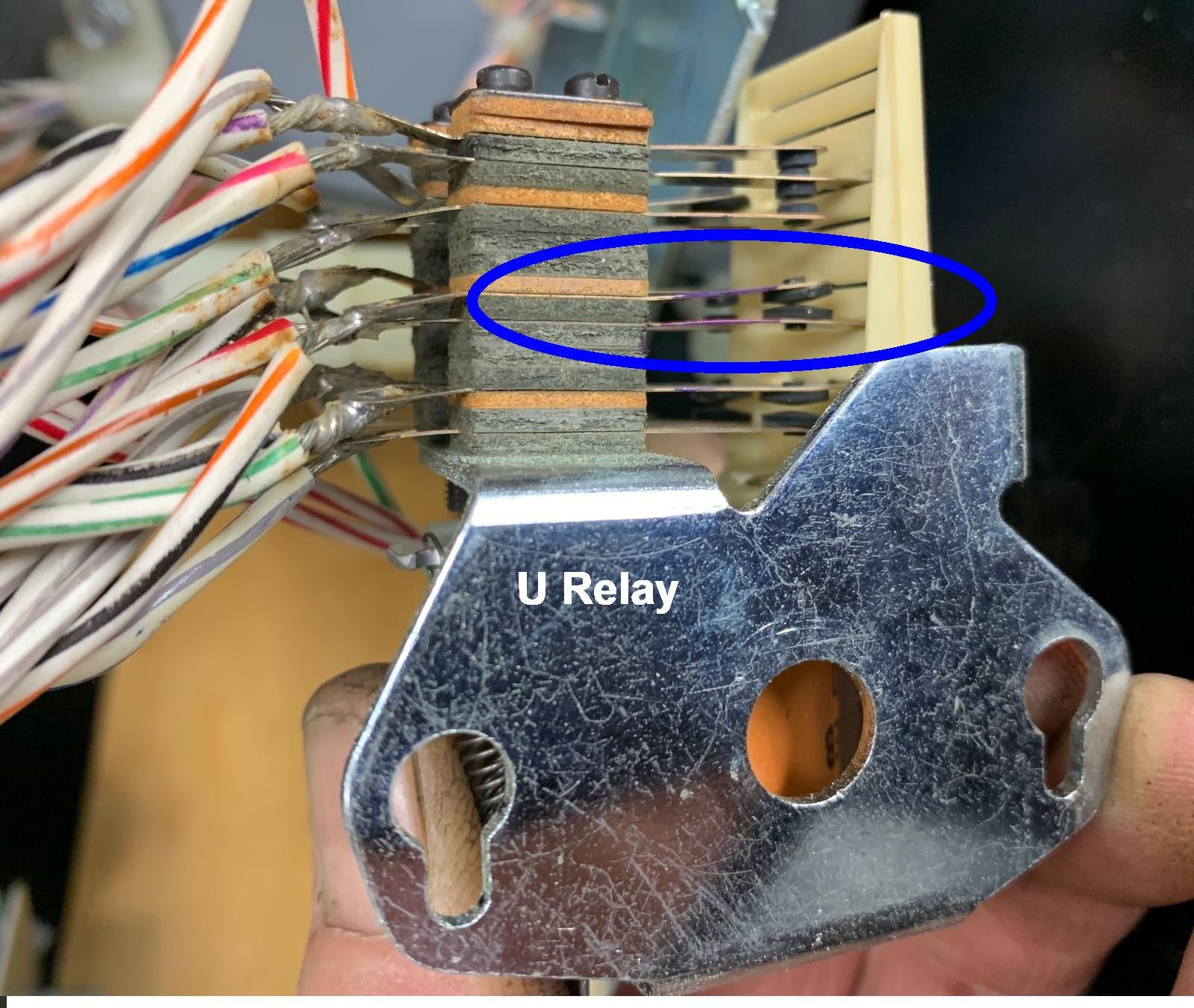
What I did was to modify the existing lower playfield U relay. There's two switches on that relay that when the ball goes on the lower playfield, it turns off the main playfield flippers when the U relay energizes. But WHY does it do this? what is the point? I mean there are separate flipper buttons for the main playfield... why turn them off??? WHY???

Well there's NO point in this. And best I can tell, unless someone can explain this to me, there's no good reason to do the Pascal Z relay modification. I just don't see the point. I mean I'm sure he has a good reason for the Z relay, but what a cluster screw! It's a shite load of work to do this Z relay modification, and i really can't justify it.

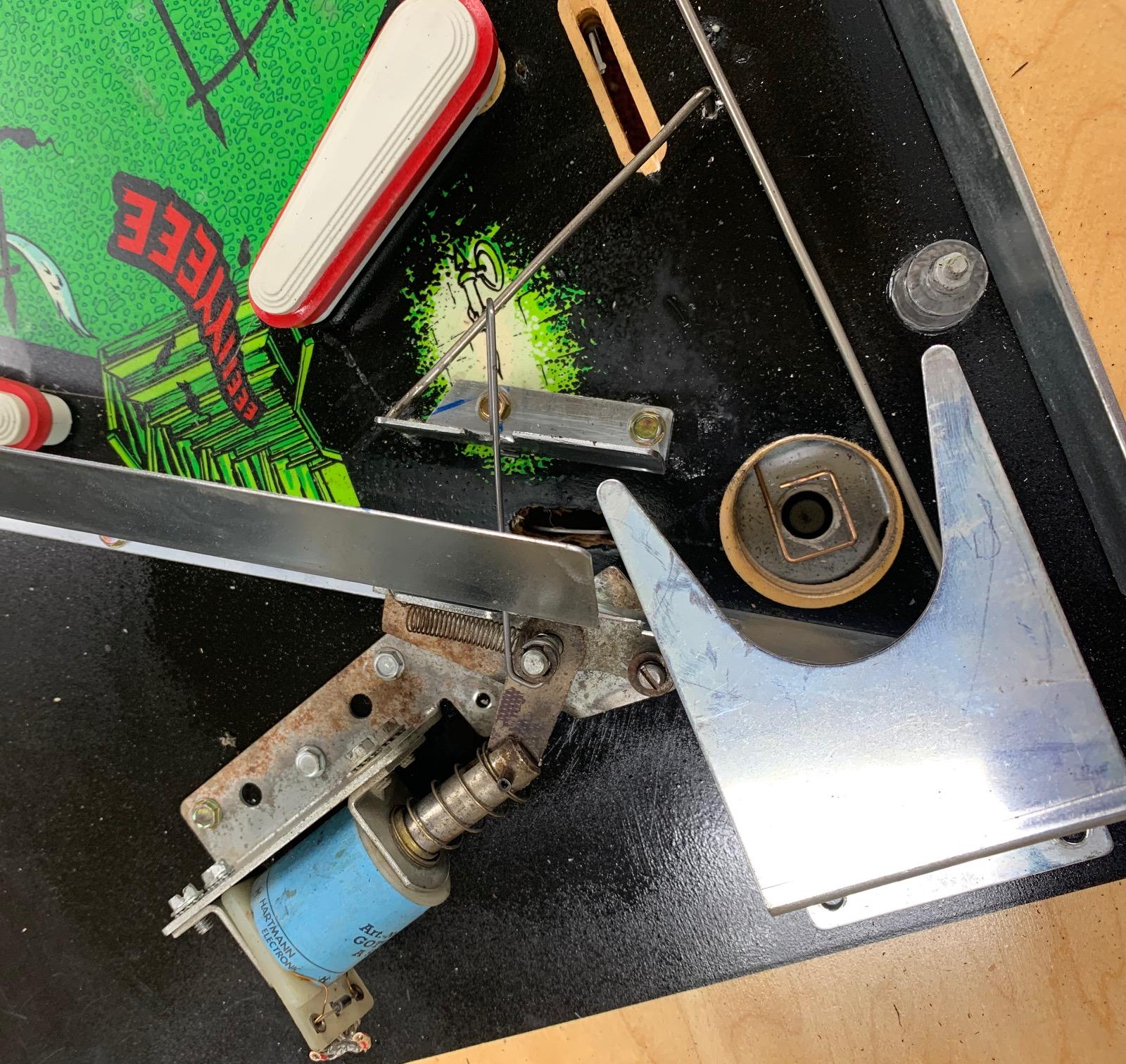
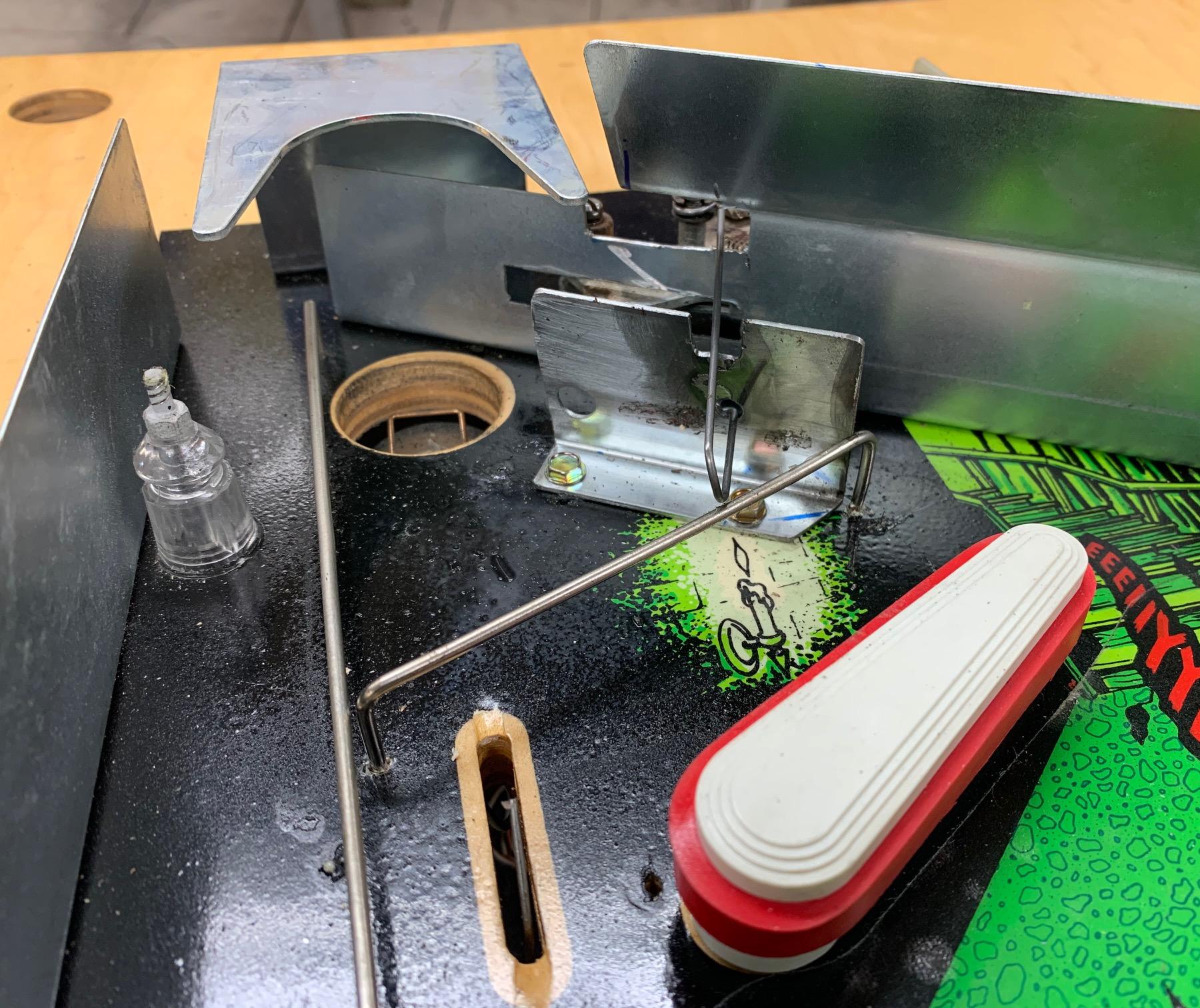
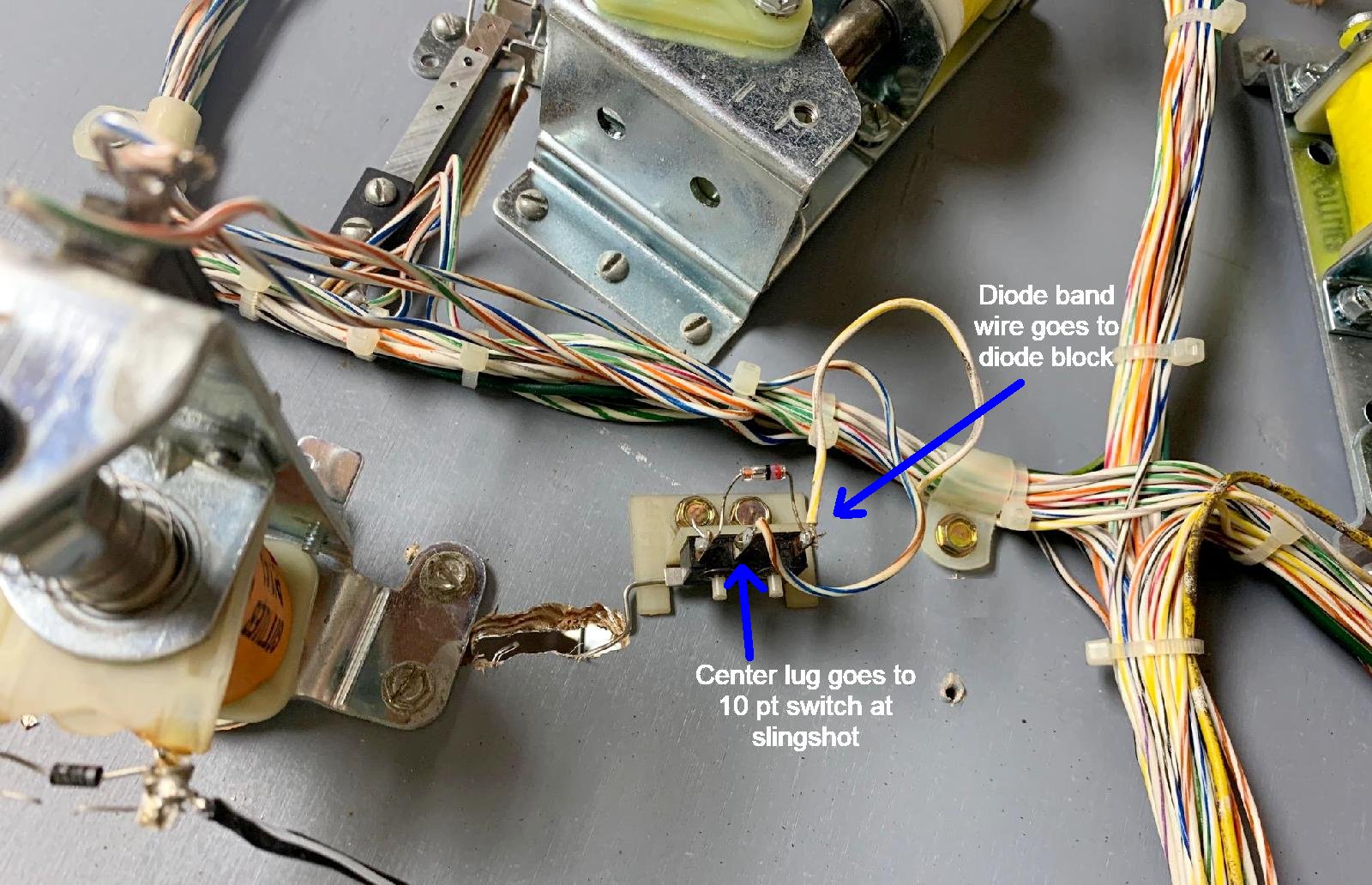
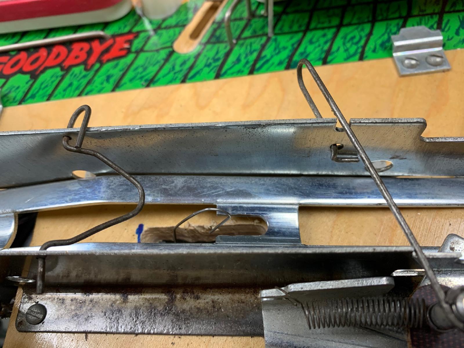
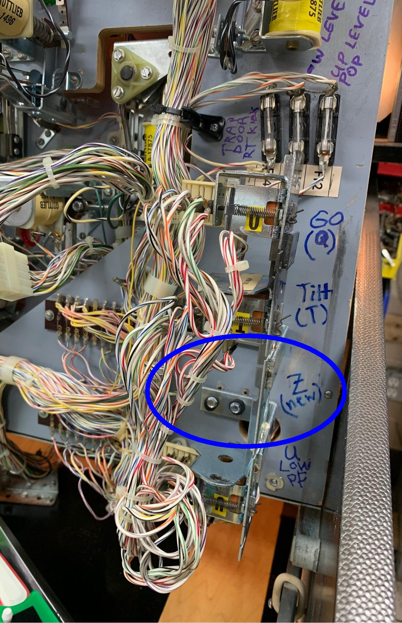
Instead what I did was modify the U relay. There's two NC switches that open on this U relay when the U relay energizes (when a ball goes to the lower playfield, or when you're in Haunted House Multiball)... what I did was just bend those NC switches so they never open. Basically anytime the U relay pulls in (ball on the lower playfield or multiball), the main flipper buttons still work...

http://www.pinrepair.com/sys80/hhmb_main08.jpg

http://www.pinrepair.com/sys80/hhmb_main09.jpg

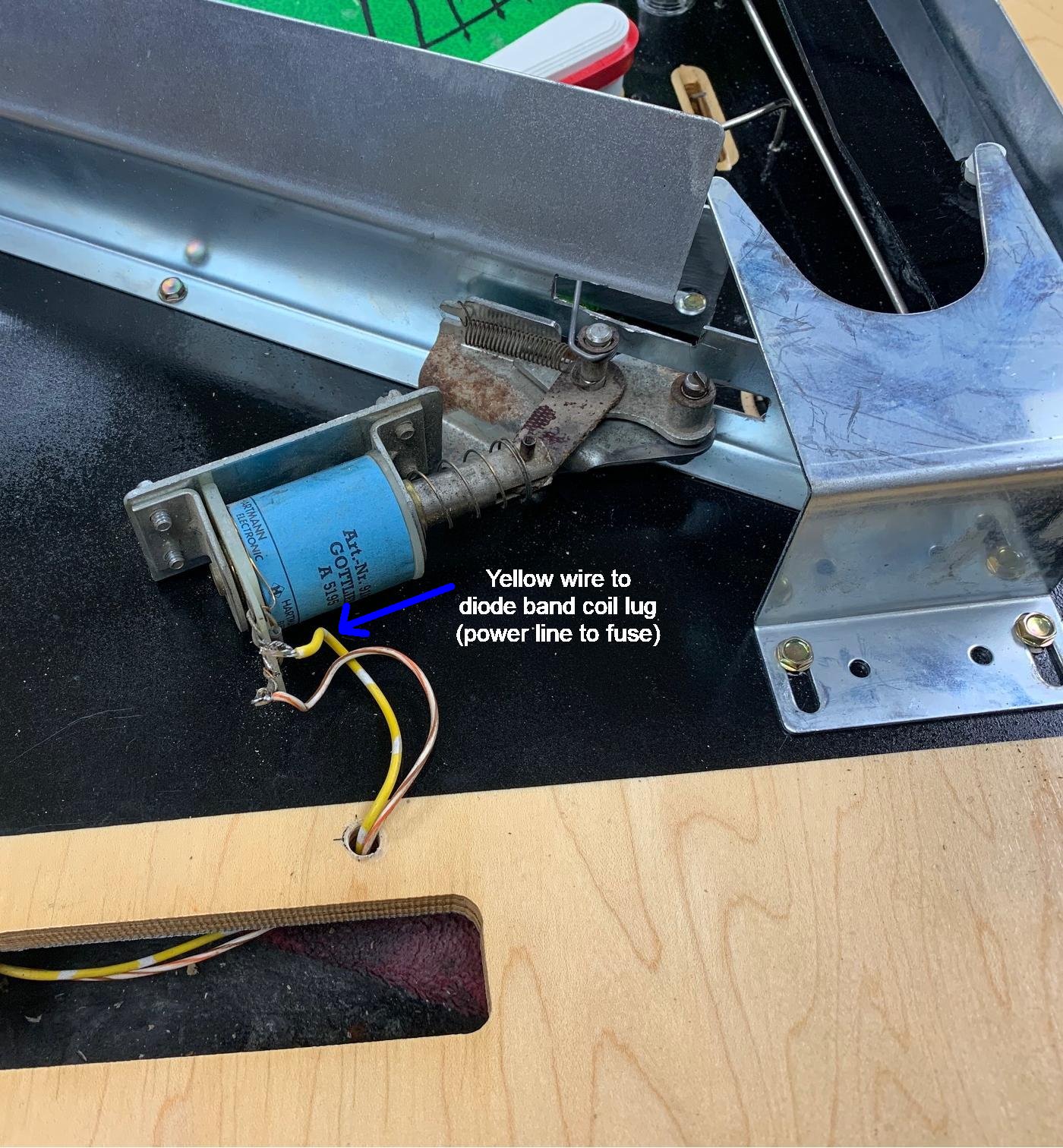
Right now this is the only modification I do for the main playfield flippers. Until I can come up with a good reason to add this Z relay. I will play the game a bunch and see if i can come up with a reason for this Z relay... But for now, this is a MUCH easier approach with less modifications and changes from the original set up.

#113 3 years ago

Another thing I forgot to document is the access to the lower playfield VUK from the main playfield. Since the game is multi-ball now, you don't want two balls to end up going down the VUK tube from the main playfield to the lower playfield. Pascal documents this nicely in his paper too. So a gate is added to the front of the main playfield VUK tube, so no balls can access the lower playfield VUK tube directly from the main playfield. Note the flat playfield plastic now sits on top of the newly added gate. Not a big deal, but it does look slightly different than original.

http://www.pinrepair.com/sys80/hhmb_main10.jpg

We played the Haunted House Multiball all night today, and found it to work well. My 'easy' modification to the U relay really worked fine, with no issues. I highly suggest doing this instead of Pascal's added Z relay method...

PBDB for the VUK
============

The only think left is to add a Pop bumper driver board to the lower playfield for the VUK. without the PBDB, the lower playfield VUK coil is a bit inconsistent. The PBDB makes it really consistent. Because you don't want VUK ball failures, where it takes two tries to get a ball from the lower playfield up the VUK tube to the main playfield. If that happens during multiball, a second ball can get released to the VUK, and then you get a ball stack in the VUK. It will eventually clear it, but it takes several times and a lot of praying!

Frankly a better approach would have been to put a switch on that gate (that we just added). Don't release a ball from the (newly added) lower playfield ball trough to the VUK, until the current ball launches and activates that Main Pf switch (verifying that the ball did in fact get out of the VUK and onto the main playfield). this would really prevent two balls from getting into the lower playfield VUK. After all, isn’t that the reason we added the lower play field ball trough in the first place? To leave out the switch kind of seems like you only did half the job. that's how i would have done it, as it really prevents two balls from getting into the VUK. The game has a hard time launching one ball straight vertically, much less having to deal with two balls at the same time.

If you want more consistent VUK action, the best thing to do is replace the relay on the lower playfield with a pop bumper driver board (PBDB). This way you will get 100% exactly the same pulse length to the VUK coil, meaning you add consistency to the VUK. Currently with the relay and the high voltage switch on the relay, it can be hit or miss. Sometimes it's a clean VUK firing, sometimes not so much. and as the game ages, those high voltage switch contacts pit and wear, meaning consistency gets worse and worse.

It's pretty easy to add the PBDB to the VUK, but that board requires 5 volts DC to work, and there's no 5 volts on the lower playfield (you have to bring it there with some wiring). The problem with doing this multiball modification is getting +5 volts to the lower playfield. In order to do that, in the past, I just added a wire from the backbox to the lower playfield through plug A9J2, through an empty .093" round pin plug going to the lower playfield. But with the addition of the multi-ball release coil, there is no longer an empty plug pin in A9J2. Which means there isn't a clean way to do this (you'll have to add a new connector to the harness.) Not a huge deal but something to think about...

1 week later
#114 3 years ago

Been playing the Haunted House multiball and have come up with a couple small modifications.

First on the U relay. since we didn't add the Z relay that Pascal documented, (we cheated, see up a couple posts), I noticed during multiball it turns on the U relay to light the lower playfield GI. But at the same times, this GI circuit goes through a Make-Break switch, and turns *off* the main playfield GI lights. We really don't want that to happen. So what I did was modify the make-break GI switch on the U relay. Basically the middle blade of the make-break is the GI power. when the relay is not energized (ball on main playfield), the make break has the top switch closed. Go to the lower playfield and the U relay pulls in, and the make-break now sends power to the lower blade.

What I did was to bend the top blade so it's always closed. this way the main playfield GI lights are always on. Now when the ball goes to the lower playfield and the U relay pulls in, the main playfield GI lights are still on, in addition to the lower playfield GI lights.

it's a small comprise in my eyes. Attract mode is a bit different too... every few seconds the lower playfield GI lights turn on (and main playfield GI lights go out). With this modification the lower playfield GI lights will still go on, but the main playfield GI lights also stay on.

http://www.pinrepair.com/sys80/hhmb_main11.jpg

Another thing I did was to change the VUK plunger on the lower playfield. I used a slightly modified Williams VUK plunger that has about 3/8" long length. I found this gives much more consistent upkicks. This is important, because you don't want a lower playfield VUK upkick failure (because if in multiball, this can cause problems.)

10 months later
#115 2 years ago

I’m curious how you wired in the switch so that the VUK doesn’t release a ball until the ball has left the lower play field. i’m in the middle of trying to track down the rest of the parts for my haunted house.. they are next to impossible to find

Promoted items from Pinside Marketplace and Pinside Shops!
From: $ 10.00
Playfield - Toys/Add-ons
Toast-Mach1 Mods Shop
 
From: $ 1.49
Playfield - Toys/Add-ons
Daddio's 3D Printed Mods
 
3,950 (OBO)
Machine - For Sale
Centerport, NY
2,950 (OBO)
Machine - For Sale
Shakopee, MN
From: $ 1.00
Playfield - Other
Rocket City Pinball
 
$ 1,159.00
Flipper Parts
Mircoplayfields
 
Hey modders!
Your shop name here
There are 115 posts in this topic. You are on page 3 of 3.

Reply

Wanna join the discussion? Please sign in to reply to this topic.

Hey there! Welcome to Pinside!

Donate to Pinside

Great to see you're enjoying Pinside! Did you know Pinside is able to run without any 3rd-party banners or ads, thanks to the support from our visitors? Please consider a donation to Pinside and get anext to your username to show for it! Or better yet, subscribe to Pinside+!


This page was printed from https://pinside.com/pinball/forum/topic/haunted-house-resto-plus-multiball-and-speach/page/3 and we tried optimising it for printing. Some page elements may have been deliberately hidden.

Scan the QR code on the left to jump to the URL this document was printed from.