Quoted from MarkG:This is a pretty cool circuit that I haven't studied before. I need to spend some more quality time with it to grok it.
This is the most interesting circuit I've studied in a while. It's a unique problem and a very clever way of solving it. (More) Kudos to Mr. Neyens.
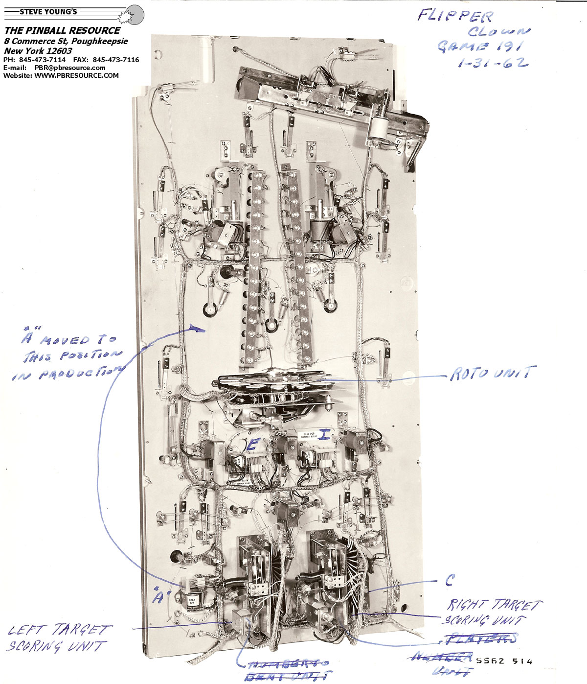
For those who aren't familiar, there are two columns of lights on the playfield (left and right). Hitting the Roto Targets or appropriate rollovers will turn on one light in each column. Once both columns have one light on the game will award an added ball if the light in the right column has a higher value than the light in the left column, then both columns will be reset.
It's common and relatively easy to determine if two things are "equal" with circuitry. Most games have a match circuit for example that awards a replay if a digit of the score matches (or equals) the position of a hidden stepper.
What's unique in this situation is that the game must evaluate a "greater than" function which is more complicated and interesting than an "equal to" function. To explain how that's done I've simplified the schematic above and animated it.
In the first animation both columns of lights start in their reset positions as shown in the schematic above and the left Roto Target is hit while 7 is showing. The result is that the Left Target Scoring Unit takes seven steps:
 Left side first part 1.gif
Note that the Left Target Scoring Unit has two pairs of wipers that move together as the unit advances. Also note that the L2/Left Target Scoring relay is active while the Left Target Scoring Unit advances which closes the two L2 switches in red.
The second animation picks up where the first animation left off. The left column has the #7 light on and the right Roto Target is hit while a 12 is showing. In this case a ball should be added. To achieve this the W/Win relay in the upper left corner must be active when the advancing stops.
Left side first part 2.gif
The P2/Right Target Scoring relay is active while the Right Target Scoring Unit is advancing which closes the two P2 switches in red. When the Right Target Scoring Unit steps to position 8 (which is one greater than the Left Target Scoring Unit at postion 7), a circuit is completed that fires the W/Win relay as shown in red. When it steps to position 9, the circuit to the W/Win relay is broken, but the W/Win relay Lock In circuit in red keeps the W/Win relay active. The Right Target Scoring Unit continues stepping to position 12.
In this scenario (when the left column light is set first) the Right Target Scoring Unit is essentially compared to the Left Target Scoring Unit at each step as it advances to position 12. The Left Target Scoring Unit has a 2nd wiper that points to the position one higher than the current Left Target position (8 in this case) and once the Right Target Scoring Unit reaches it a circuit the the W/Win relay is completed.

