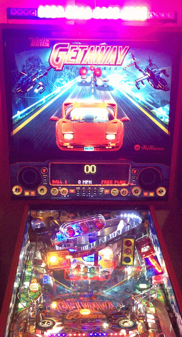
I love my Getaway, after all it was my introduction into pinball as the first game I ever purchased. The game has so much going for it, and I've always loved the theme (what guy at some point doesn't fantasize about being chased by the police in his high-performance supercar?). However, one thing has been missing from the this pin . . . until now. Part of the visceral experience of being chased by the police are those rapidly blue and red flashing lights coming from behind you permeating your entire field of vision. Your heart is pounding, your mind is racing, and your senses are overwhelmed.
A couple of weeks ago  EStroh recommended that I install a lightbar topper on my Getaway, as he's done it on both his High Speed and Getaway pins. After chatting about it with him, it sounded like a good idea so I decided to go for it. Up to this point he had wired his into the beacon light using a relay so that it fired whenever the beacon light was on. However, I had a "take it to the next level" idea.
For those not familiar with the PinSound Motion Control shaker, it is a must have in my opinion as a companion to the PinSound board itself. I remembered that the Motion Control board for the shaker also has an additional relay built in that can be controlled based upon sound events. You can close (turn on) the relay selectively by pairing it to any sound(s), set it up to 10 seconds, repeat it up to 10 times, and set a pause between repeats. Connecting the lightbar this way opens it up to all sorts of possibilities. I was able to program the lightbar to fire based on multiple events in the game (e.g. running the red light, redline mania, various police callouts, jackpots, end of the game, etc.)
Upon getting everything installed, programming and tweaking the relay events, and playing several games, I absolutely love it! It adds a whole new immersive experience when playing the game. Overall, the parts needed and installation are fairly straight forward and probably a 4-5 on a 10 point difficulty scale, so just about anyone can do this DIY in an hour or less. For those interested, here are the prerequisites, parts required, and installation instructions to install the way I did. If you don't have a PinSound board and Motion Control Shaker but still want to add a lightbar, then I'm sure EStroh would be happy to post instructions for wiring it to the beacon light if someone requested it.
PREREQUISITES
- One of the following PinSound Audio Boards: PinSound 1 (v1.3/1.4 - v1.2 is not compatible), PinSound Plus, PinSound Neo
- PinSound Motion Control Shaker with Control Board
- One of my PinSound Getaway orchestrations (or anyone's orchestration that follows my folder naming convention if you want to use my supplied pinsound.config file with shaker and relay events pre-programmed): https://www.pinsound-community.org/index.php?/files/category/22-getaway
- My modified pinsound.config file with relay programming (or you can do your own), just PM me with your email address if you would like me to send you a copy AT NO CHARGE.
PARTS REQUIRED (ABOUT $50 ASSUMING YOU ALREADY HAVE ALL OF THE PREREQUISITES)
- 27" TeddyTT Red and Blue Police Emergency LED Strobe Bar (or similar lightbar): https://www.amazon.com/dp/B07FDD9GZH
- AC to DC Converter 12V Cigarette Ligher Socket: https://www.amazon.com/dp/B09CTMJJTJ
- 2 x Woodscrews to secure lightbar to backbox (not included with lightbar)
- A short jumper wire (optional)
INSTALLATION | DO ALL OF THIS WITH THE MACHINE UNPLUGGED FROM WALL SINCE THE SERVICE OUTLET IS HOT EVEN WITH THE PIN TURNED OFF
- Disconnect the white coupler that joins the wires from the power/control piece to the lightbar.
- Remove the screws and extra brackets that come pre-attached to the lightbar as you will not need them. You will have to remove one of the endcaps from the bar to slide all of the screws out of the channel, but this is simple and non-destructive as the cap is secured by a few small screws.
- Remove the two support brackets from each side of the light bar secured by the two silver screws on each side, and reverse the brackets so they are pointing outward. You can actually keep them inward, but when turned outward they are a perfect fit for aligning the lightbar to the backbox width and easier to screw down.
- Test position the lightbar in front of the beacon light and align such that it is parallel to the front of the back box, then secure to the backbox using one screw on each side (the light bar brackets should fit perfectly in the width of the backbox).
 IMG_6870 (resized).JPG
- I chose to rotate the lightbar at an upward angle then lock in with the two bracket screws on each side. When initially pointing directly forward the lights were blinding to me, but the slight angle is perfect. As a FYI, I'm 6'3" so depending on your height you may prefer less or more angle.
IMG_6871 (resized).JPG
- Next, run the cable around the back and through one of the vent holes at the top of the backbox. You may have to loosen or remove one of the screws inside the backbox to give you enough flex in the grate to feed the wires through.
IMG_6869 (resized).JPG
- Now connect the controller to power and run that wire up through the back of the cabinet and into the backbox. To do this, plug the AC to DC converter into the service power, plug the lightbar cigarette controller into that, run the wire to the back of the pin and up into the backbox.
IMG_6872 (resized).JPG
- You'll see the controller has two switches on it. The one with the red light is the power, and the other is the toggle switch for changing modes. The good news is that whatever mode you select is always recalled even after power loss (I actually turn my pins off at the wall switch, so this is a major plus not having to reset modes every time). My personal favorite pattern is in the animation below, but you can set yours to whatever you like.
IMG_6873 (resized).JPG
- At this point you should have both ends of the cable in the backbox with the white plugs on the end. Now you want to remove the red lead from each connector using a small pin or screwdriver while leaving the black and yellow wires attached to the connectors. Once you remove the red wires, then go ahead and couple the connector with the black and yellow wires. Optionally, instead of removing the red wire pins from the connectors you can just cut and strip the wires. Once everything is hooked up, I suggest covering any exposed connections with electrical tape or heat shrink (not pictured).
IMG_6874 (resized).JPG
- Next, you will connect the red wires to the relay on the motion control board. The red wire coming from the power/controller goes into the IN A (far left) port and the red wire leading to the lightbar goes into the OUT A (far right) port. Since I left the pins in my wires, I used a short jumper wire to hookup the OUT A connection (you can directly connect the IN A without a jumper wire since the lead fits into the slot).
IMG_6875 (resized).JPG
FINISHING YOUR SETUP
- Plugin your pin and turn on your switch for the lightbar. The red light on the lightbar control should be illuminated, however, the lighbar will not turn on yet because the relay is open.
- Remove your PinSound USB drive and place it in your computer. Navigate to the orchestration folder containing the orchestration you wish to apply the lighbar programming to.
- Delete the pinsound.config file in that folder (assuming it is one of my orchestrations or another that uses my folder naming convention), then copy the pinsound.config file you get from me in its place.
- Replace the USB into your PinSound, power on your pin, and select the orchestration (if you have more than one installed) with the new relay actions applied.
HIT THE GAS, DON'T LOOK BEHIND YOU, AND PLAY SOME PINBALL!
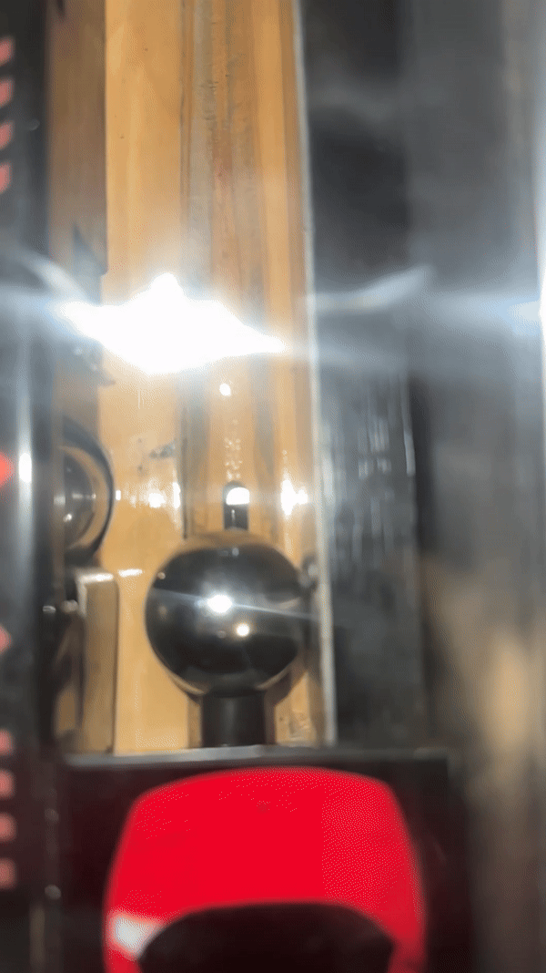
Here's my lightbar topper connected to my PinSound Motion Control fully installed . . .
IMG_6876.JPG
And here it is in action!
Getaway Lightbar.gif
 Fort Worth, TX
 Edmonton, AB

