(Topic ID: 124724)

Flight 2000 Club - members and fans welcome!

By Snux

9 years ago


Topic Heartbeat

Topic Stats

  • 2,325 posts
  • 148 Pinsiders participating
  • Latest reply 28 days ago by chas10e
  • Topic is favorited by 79 Pinsiders

You

Linked Games

Topic Gallery

View topic image gallery

pasted_image (resized).png
Screen Shot 2024-03-16 at 5.55.11 PM (resized).png
PXL_20240310_020948866 (resized).jpg
PF (resized).JPG
IMG20230430200630 (resized).jpg
IMG_4170 (resized).jpeg
IMG_4169 (resized).jpeg
9054E268-F271-40DC-805F-FFAB1924C7B8 (resized).jpeg
9AE80644-F808-46B1-9F40-1EDD65ADB443 (resized).jpeg
15ADFD65-8328-4778-834A-E5EA14EF10DB (resized).jpeg
IMG_9952 (resized).JPG
IMG_9950 (resized).JPG
IMG_9947 (resized).JPG
IMG_9944 (resized).JPG
5D2006E0-2E7A-4A88-A92F-E32EC01C9A5C (resized).jpeg
IMG_9886 (resized).JPG

You're currently viewing posts by Pinsider Quench.
Click here to go back to viewing the entire thread.

#400 4 years ago
Quoted from Tomass:

Trying to figure out why these .100 terminals are shaped like this. They are not consistent either and I don't think they will fit into the housing. Anyone have any suggestions?

Those were "reel" packaged terminals that someone cut to single pieces. You can cut them to about the right width, but it's a PITA to do.
Reel packaged terminals are cheaper because they're supplied in bulk and are meant for automatic crimping machines that also cut them from the reel.

9 months later
#793 4 years ago
Quoted from Lovef2k:

Another problem with flipper hop on the early Sterns is that the original flipper bats are NLA. The reproductions are fatter and causes a not so smooth transition to the flipper from the inlane.

Can you post some pictures showing the plastic flipper bat outer axis diameter width difference between original and new bats?

3 months later
#938 3 years ago
Quoted from clodpole:

Thanks! BTW, please explain thermal paste.

Semiconductors that carry a lot of current can dissipate a lot of heat. Heat is their enemy and will shorten their lives. In your case it's the bridge rectifiers, particularly the one for the feature lamps.
To disperse heat away from these semiconductors, they can be attached to a metal heatsink. The more surface contact between the semiconductor and the heatsink means you get better heat transfer away from the semiconductor that the heatsink can disperse. Neither of the contact surfaces are going to be perfectly flat, so thermal transfer paste is applied between the two to fill in the microscopic spaces/pits and improve thermal conductivity through greater surface contact between the two.

#940 3 years ago
Quoted from slochar:

Adding, that when you use thermal paste - don't glop it all over the place. You want a *thin* layer; too much and it will act as an insulator.

Right, the thermal transfer paste is used to fill in the spaces, that's all. It won't beat metal to metal contact so you don't use too much that becomes an insulator.

BTW, not all thermal transfer pastes are created equal..

#946 3 years ago
Quoted from clodpole:

Well, that's a good question. I'm presuming at C7 on the sound board, but....

Yes, barakandl was talking about capacitor C7 on the Stern SB-300 sound board.

https://pinside.com/pinball/forum/topic/humming-sound-in-old-sterns#post-5765272

#957 3 years ago
Quoted from tyking:

Flutter/machine gun:

Fluttering is caused by an open circuit in the "hold" winding on the flipper coil.
The flipper coil has two windings, one powerful to thrust the flipper, the other low power to hold the flipper up.

At idle, the EOS switch is closed which shorts out the hold (thin wire) winding on the flipper coil.
Player presses the flipper button, which causes full 43 volts to go through the thrust (thick wire) winding on the flipper coil.
The flipper reaches the end of the stroke and opens the EOS switch.
Opening the EOS switch now puts the hold winding in series with the thrust winding to hold the flipper in the up position with reduced power to prevent burnout.

However in your case the hold winding is open circuit so when the EOS switch opens, current through the total flipper coils collapses so the flipper falls back.
When it falls back enough it closes the EOS switch, which now re-energizes the thrust winding. After the EOS switch opens again the open circuit hold winding fails to hold the flipper in the up position and the flipper falls back again - rinse and repeat.

With the machine OFF, put a piece of paper between the EOS switch so it no longer makes contact and measure the resistance across the two yellow wires on the flipper coil lugs. You should measure around 320 ohms.

#961 3 years ago
Quoted from tyking:

Holy crap, I though EM schematics were crazy, but now looking at the schematic for F2K I’m cracking up. I thought I would check and see if there are particular transistors to check, but I’m not sure I’ve found all the flipper switch sections!

Transistors don't drive the flippers on these games.

Quoted from tyking:

Flutter/machine gun: with the paper: the only connection showing Omhs is in the pic (3.5 on the first part of the omhs reader setting) the rest are showing 0.

When you say the rest showed 0, do you mean the meter reading didn't change when you connected the meter probes or the meter reading changed to zero when you applied the meter probes (i.e. just like when you touch both meter leads together as a short circuit)?

Is your multi-meter auto-ranging or do you need to set the range you're measuring? i.e. if you have multiple ohms ranges like 200, 2k, 20k, 200k, 2M you need to select 2k ohms range to check the hold winding resistance.

See the image below with the thin hold winding wires highlighted. Very gently prod those wires to see if any are loose/broken. They sometimes break at the point of connecting to the lug.

Flipper_Windngs1.jpgFlipper_Windngs1.jpg

#969 3 years ago
Quoted from tyking:

Here is my markup of the schematic. Is this right? I forgot to check the other flipper, which is working, to see if the multimeter readings are different.

The diodes on your flipper coil are installed backwards in reference to the schematics, however the wires and EOS switch have been alternatively connected on the coil to compensate. Your connections as-is will work but they don't 100% match the schematics.

Quoted from tyking:

Didn’t seem to work. And correct reading of the lugs is : 1(thick) - 2(thick) - 3(thin) is:

1-2 = 0 (meaning it starts at 1 and goes to 0)

Everything else is “negative” meaning it starts at 1 and doesn’t move.

This is at 200k setting.

Anyone know what this means and/or how I can rule out the diodes? Thanks.

To measure the resistance of the two windings on the flipper coil, you must open the EOS switch (put a piace of paper between the contacts).
Set the multi-meter to "200" ohms range.
Put either meter lead on the middle yellow coil lug and the other meter lead on the other side lug with the green wire.
You should measure around 4 ohms.

Now set your multi-meter to "2k" or "2000" ohms range however your meter is marked.
Put either meter lead on the middle yellow coil lug and the other meter lead on the side lug with blue-white and yellow wires.
You should measure around 320 ohms. If the meter reading doesn't change when you put the probes on the lugs then the hold winding on the coil is open circuit. If you can't find the break in the thin winding wire then you might need to get replacement coils. As mentioned that wire usually breaks next to either lug it's soldered to.
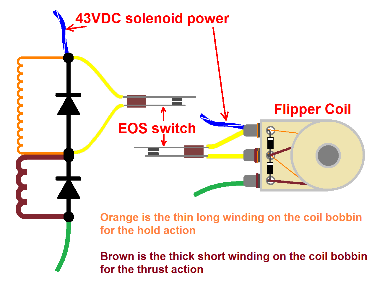
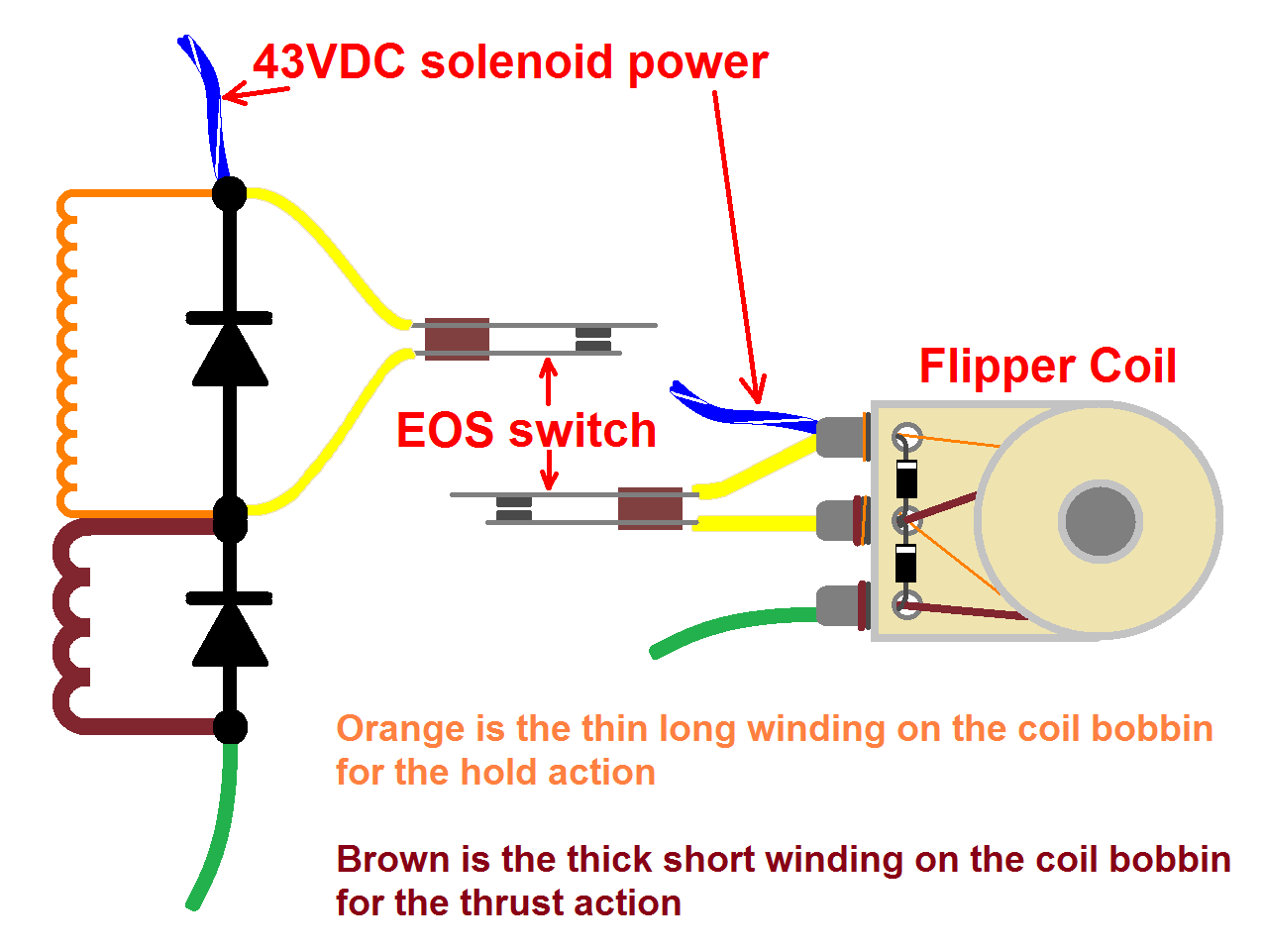
The thin winding wire is the orange coil wire winding as shown below. The left side is the schematic for your setup, the right side represents your coil wiring.

Flipper_Coil.gifFlipper_Coil.gif

#974 3 years ago
Quoted from tyking:

Looks like I’ll just have to replace the coil. I couldn’t find the end that would go to the middle lug, and when I was looking around for it I severed the thin wire somewhere. I did resolder the thin wire after severing it. But I still have the machine gun effect. If I put an old em gottlieb flipper coil it won’t ruin anything right?

So to confirm, you do not measure 320 ohms resistance across the two lugs with the thin wire? Sounds like you need a new coil.

Quoted from tyking:

If I put an old em gottlieb flipper coil it won’t ruin anything right?

Don't do it, EM flipper coil is not appropriate for this application and will likely cause other damage .

1 week later
#996 3 years ago
Quoted from tyking:

but how about from an SS Bally. They are 25-500 / 28-1000.

That is not a flipper coil from a Bally SS, it's from a Bally EM.

Quoted from tyking:

BTW, why are the Bally’s hold winding so strong compared to the Stern?

The hold windings are the same, you're comparing the wrong coils.

1 month later
#1090 3 years ago
Quoted from tyking:

Are Molex 22-01-2201 interchangeable with 22-01-2171?

The only difference between these two Molex part numbers is the number of circuits.
xx-xx-x17x is 17 circuit
xx-xx-x20x is 20 circuit

They're both 0.100" spacing between pins.
Not significant here, but one of those part numbers isn't right. The white housing has the side polarising ribs so possibly the part number is 22-01-3207 or it could be a non-Molex brand housing.

#1100 3 years ago
Quoted from tyking:

do you mean jumper cable from J2 to lamp driver input J4?

Yes, it was a typo. It goes to the lamp driver board at J4

Quoted from tyking:

On the attached pic

Your attached picture is of the switch matrix on the playfield. While by coincidence it might share some same wire colors, they have nothing to do with the signals to the lamp driver board/VSU.
Unfortunately Stern didn't mark the wire colors for the VSU/lamp driver board signals you're looking for.
The only info there is, is the wiring diagram page that tells you where the wire locations from the lamp driver board J4 come from. So you'll have to check the code next to the J4 connector that tells you which board/connector/pin the wires come from.

See below:
A2 = the Power Rectifier board
A3 = the Solenoid Driver board
A4 = the MPU board
A5 = the Lamp Driver board

Wiring_A5J4_1.pngWiring_A5J4_1.png

#1106 3 years ago
Quoted from tyking:

Now I get it. I will start there. Thanks.

Just incase it wasn't obvious/mentioned, the 17 pin connector with the multi colored wires is originally part of the generic backbox harness that connects to the J4 connector on the lamp driver board.
When Stern designed the VSU-100 speech board, they piggy backed it off the signals to the lamp driver board. So now, that multicolored wire 17 pin connector hooks up the the VSU-100 board and the 17 pin ribbon cable passes the signals to the lamp driver board.

i.e. you can plug that multicolored wire connector directly onto the lamp driver board J4 connector and the feature lamps will work (if you ever need to bypass the VSU-100 speech board for whatever reason).

#1109 3 years ago
Quoted from tyking:

Such a fabled connector, it should have its own chart:

Nice work.

Quoted from tyking:

I think I found a typo in the schematic where it references A2J2-14. It should be A2J3-14, b/c there are not 14 pins on J2 on that board.

You are 100% correct - another Stern manual/schematic error. LDB J4 pin 11 (A5J4-11) comes from A2J3-14.

These are the LDB J4 wire colors from a late Stern MPU-100 game: Only one a little different to yours is pin 13.

J4-01 White-Red
J4-02 Red-Black
J4-03 Black-Green
J4-04 Orange-Green
J4-05 Orange-Red
J4-06 Brown-White
J4-07 Brown-Yellow
J4-08 - key
J4-09 -
J4-10 -
J4-11 White-Black
J4-12 -
J4-13 Orange-White
J4-14 Yellow-Blue
J4-15 Red-Yellow
J4-16 Green-White
J4-17 Green-Black

#1113 3 years ago
Quoted from tyking:

So I finally got the connectors crimped, and the machine is running again, like a champ. Has to put it at J2, b/c it is 20 pin housing and doesn’t fit at J1.

Cool.
If a new connector housing is too long I normally cut the excess off with a blade to make it the right length.

1 month later
#1248 3 years ago
Quoted from FlipperFanatic:

When it powers up it stays in test mode.

When all the 32 DIP switches on the MPU board are set to "off", the game will boot up into factory burn in test mode.

Go through the Flight 2000 manual and configure the game play settings via those 4 banks of 8 DIP switches on the MPU board as you desire. You need to move at least one of those switches to the "on" position.

#1250 3 years ago
Quoted from FlipperFanatic:

I reseated the plugs and now it start a game but the only thing that works on playfield are the drop targets.

No playfield switches work? No other solenoids work? need more details to pinpoint your problem but it's going to most likely be connector issues. Did you re-terminate the connectors in this game when you replaced all the boards?

1 month later
#1276 3 years ago
Quoted from Jodannar:

Flippers on this game are meant to droop.

This ^^^

The pins are there as the reference point to align the flippers. When the flippers are down they should rest against the pins for optimum flipper angle. These Sterns are not intended to have the flippers aligned with the return lane guides like Williams machines.

There was a long discussion on this in the Stern club thread:
https://pinside.com/pinball/forum/topic/price-check-1980-sterns-quicksilver-stargazer-seawitch/page/78#post-5872885

3 months later
#1351 3 years ago
Quoted from tyking:

You don’t have to remove the diode do you?

The low resistance of the coils will cause your multi-meter to conduct in both directions across the diode meaning you get false readings. You must at least disconnect one leg of the diode so it's isolated to test it.

#1355 3 years ago
Quoted from tyking:

But If I removed all the connectors to all the boards, and displays, and I left just the 20 pin connector on the solenoid driver board, and I don’t show proper voltages at the test points on that board, haven’t I isolated the problem to the solenoid driver board?

I was only responding to your question about testing diodes on coils. I haven't been following your issue.

You say you're getting 26V at TP5 on the solenoid driver board but what are you measuring at TP3 on the rectifier board (it's the same voltage rail).
How much voltage do you measure across the C23 capacitor on the solenoid driver board (black meter lead on the capacitors negative leg, red meter lead on the positive capacitor leg).

Post pictures of your solenoid driver board.

#1372 3 years ago
Quoted from tyking:

On the solenoid driver board I am getting TP2-193v, TP4-254v, TP5-2.16v., C23 2.15v. On the rectifier board I am getting TP3-14v. I use the ground braid for ground when testing the rectifier board. Is that okay?

The voltage at TP3 on the rectifier board goes to the voltage at TP5 on the solenoid driver board. Yours are not measuring the same so you have some connection issue.

The 12 volts (14V in your case) at TP3 on the rectifier board leaves it at J3 pin 8 and goes to the solenoid driver board at J3 pin 12 (orange wire).

Looking at your J3 solenoid driver board wire connector, I see the terminal at pin 12 in the housing is not as deep as the others (it may be broken). Terminals at pins 19 and 24 in the housing look melted. You have some rework to do on that connector.

Flight2000_SDB_J3.jpgFlight2000_SDB_J3.jpg

#1373 3 years ago
Quoted from tyking:

See pics of the SDB. Thanks.

BTW, you have a number of cracked solder joints at the various pin headers on the solenoid driver board that need to be resoldered.

Flight2000_SDB_J5.jpgFlight2000_SDB_J5.jpg

2 months later
#1565 2 years ago
Quoted from DanMarino:

Machine is having big problems now. My son turned it on and the speaker makes a big gumming noise and the mpu doesn’t do the 7 beeps. Guess I’ll look at the power rectifier board fuses next. I think the general illumination was coming on still.

Wild guess, you've lost DC filtration on the 12V supply rail.
Measure the voltage on the solenoid driver board at test point TP5. If it's below say 14 volts DC then the big filter capacitor on the solenoid driver board at C23 may be bad or lost connection (possibly the ground at J3 pin 10 on the solenoid driver board connector).

#1567 2 years ago
Quoted from DanMarino:

TP5 on the Solenoid Driver Board measures about 10.5 volts.

Yep, that indicates a problem around capacitor C23. It's not filtering the 12VDC supply which is causing the buzzing from the sound amplifier and stopped the 5VDC supply for the logic boards from being steady.
The most likely scenario is you have a flaky connection on the white-brown wire at J3 pin 10 on the solenoid driver board (SDB) or J3 pin 17 on the rectifier board in the lower cabinet which is where C23 gets its ground connection from. If you measure zero volts directly across the capacitor C23 legs that confirms it. Alternatively if you measure 10.5VDC directly on the capacitor legs, then the capacitor is faulty.
It's a weak point in the design, you can add some redundancy by adding the ground mod for C23 (as well as C26 while you're there) on the solenoid driver board. Sorry I don't have ability to modify your picture right at this minute to show where the SDB ground wire mods go, maybe someone else can chime in with a photo till I can get to it later.

#1574 2 years ago
Quoted from DanMarino:

Is it normal for the flipper relay to spark?

Temporarily solder a jumper wire across the flipper relay switch contacts for the left flipper circuit so you bypass the relay switch. If the rebooting no longer happens when pressing the left flipper button then look at replacing the relay. Otherwise one of the diodes on the left flipper coil could be bad.

Quoted from DanMarino:

I've added the ground modifications for C26 and C23. I tested the voltage across the C23 legs and measured 13.5 volts.

13.5 volts still sounds a little low. Put your multi-meter on AC voltage and measure directly across C23 again. From memory you should measure around 0.3 volts of ripple if C23 is doing its job. BTW post a picture showing the replaced C23.

#1576 2 years ago
Quoted from DanMarino:

here is a photo of the front of my board from yesterday. I believe the C23 has been replaced previously by someone.

Cheers, I can't see what value the C23 capacitor is. Can you tell me how many uF it's marked with?
If you get a chance let me know what AC voltage is across that capacitor. If the voltage is too high, it could be indicative of a problem on the rectifier board that's causing the flipper resets (although I think you mentioned the rectifier board is new). It's unlikely since the resets only happen with one flipper but just want to check if it's borderline.

Quoted from DanMarino:

My pins are looking in bad shape with lots of the plating gone on them.

You'll want to also replace the crimp terminals in the connectors because they'll be in bad shape too. Plus you'll need a crimping tool if you don't have one.
Also the big capacitor at C26 looks original. If you're still using the factory plasma displays (not new LED displays), think about replacing him.

#1578 2 years ago
Quoted from DanMarino:

Looks like 15,000 uF.

The voltage across C23 is 29.7 volts AC.

Cap value is ok.
Hmm, it doesn't look like your meter is interpreting the ripple voltage on the AC setting correctly. Oh well.

#1580 2 years ago
Quoted from DanMarino:

My Fight 2000 is back in service! I replaced the diodes on the left flipper and all is working properly now!

Great to hear!

#1591 2 years ago
Quoted from DanMarino:

Are the coil winding wires connected properly on this one?

Yes, the coil windings are connected to the right lugs. With the coil on the bench, measure the resistance of the two windings to check if the coil is ok. You should read around 3.1 ohms across the lugs with the thick winding, and 320 ohms across the lugs with the thin winding.

You then need to make sure the diodes are installed in the correct orientation and then the games wires are connected to the right lugs. See the diagram below:

Flipper_Coil.gifFlipper_Coil.gif

2 weeks later
#1601 2 years ago
Quoted from DanMarino:

I'm new to reading schematics, but it looks like the Q52 transistor handles the second stage go

Something tells me the schematic might be in error and it's not Q52. The 2N5060 SCRs are used to control single lamps because of their lower current capability. The MCR106's are used to control one or more lamps. Both "Second Stage Go" lamps are listed as being driven by the same SCR so it doesn't make sense that it would be from a 2N5060 SCR.
Can you confirm both "Second Stage Go" lamps on the playfield have a white-blue wire and does it match the colored wire on the lamp driver board at connector J2 pin 5 (i.e. white-blue)?

A certain error is the "Special Lane Top" lamp is listed as coming from J2 pin 30 which doesn't even exist!

1 week later
#1611 2 years ago
Quoted from DanMarino:

I need to look at this again tonight, but I'm wondering if I connected that controlled shoot again light socket on the backbox to the general illumination by mistake? If so, is it possible that this is also back feeding to the shoot again lamp on the playfield?

The same player shoots again lamp behind the backglass and at the playfield are on the same circuit. So if you hooked up G.I. to the backbox one, the playfield one will be affected likewise.

9 months later
#1821 1 year ago
Quoted from KurtisEBear:

Then all of a sudden I lost the flippers. Checked all solenoids and nothing was active now. Checked new 1.25A SB and it was still good. Checked fuse at rectifier board and it is good. Probed test point and I get 43 V.

If all solenoids including the flippers stop at the same time and you have 43V on the playfield coils, check the 5V logic loopback wire on the solenoid driver board at J3.
A bad connection on either end of that wire will cause all solenoids/coils to go dead.

SDB_LogicPowerA.pngSDB_LogicPowerA.png

#1825 1 year ago
Quoted from KurtisEBear:

So just check the wire that connects 13 to 25 (dotted line?)

Yes.
As slochar said you can also check it by testing continuity between TP1 and TP3 on the solenoid driver board as shown in the diagram I posted.
The loopback wire provides power to the logic section in the solenoid select/drive circuits.

Quoted from KurtisEBear:

Should I also check J3-pin 17 at rectifier board?

A failure on this connection will cause the game not to boot-up. Unrelated to your issue.

5 months later
#1949 1 year ago
Quoted from JethroP:

Can anyone confirm the dimensions of the playfield glass on Flight 2000? I need to order glass and think I know what it should be, but just want to check. Thanks.

Do the glass dimensions on Marcos look about right when measured against your machine?
https://www.marcospecialties.com/pinball-parts/1E-265-GW

1 month later
#2034 1 year ago

This is an electrical problem, it should be resolved at the source by removing the switch matrix wire acting as an antenna away from the flipper wires with their current transients.

Some people have had success with 2.2uF high voltage capacitors across the flipper EOS switches to clamp the current spikes.

From my experience, it usually happens on fast react coils that are connected to the switch matrix wire shared with the outhole and that's because the outhole return wire usually runs the length of the playfield together with the flipper wires.

#2036 1 year ago
Quoted from slochar:

I'm curious to see how much less 'active' the pops and slings will be.

Well this is the problem. Masking it with software means increasing the chance of making the fast react coils response becoming sloppy.

Or how about this idea, use the display interrupt service to scan the fast react coil switches for two or three successive service activations and mark the switch cache accordingly..

#2038 1 year ago
Quoted from slochar:

Do you mean service activation the register that reacts for scoring? I call that one the action register. At any rate, I hacked something quick in there to use the action register reaction instead of what it was currently using (the initial/history registers is what I call those).

I call it the 'valid' switch register.
Since the display interrupt service occurs at 400Hz the switches can be sampled at a faster rate.
Copy the zero crossing code for sampling the switches to the end of the display interrupt service, but only for the strobe line the fast react coils live on. Remove this from the zero crossing code so they don't conflict.
Then as you've done make the fast react coils fire on a valid action register flag.
The faster sampling rate should not affect the response of coil activation and give a better idea of a valid action switch if it's been sampled twice in a row as active.
All hypothetical of course.

#2040 1 year ago
Quoted from slochar:

So you think I should sample just the action/valid register in the display interrupt instead (even though it's populated in the zero cross)?

No. The idea is to populate the action/valid register in the display interrupt service rather than the zero crossing (for the fast react coils only).

Quoted from slochar:

sample the action register in the fast react (which is in zero cross anyway)

Stern PIGS checks and fires the fast react coils in the zero crossing? Bally doesn't.

2 months later
#2132 1 year ago
Quoted from daly124:

Anyone have a source to get these drop target reset links?

This pinsider made some with spares, maybe see if he still has them available:
https://pinside.com/pinball/forum/topic/price-check-1980-sterns-quicksilver-stargazer-seawitch/page/147#post-7167451

Promoted items from Pinside Marketplace and Pinside Shops!
$ 10.00
$ 12.00
Playfield - Toys/Add-ons
UpKick Pinball
 
$ 20.00
Playfield - Protection
arcade-cabinets.com
 
$ 69.00
$ 3.00
Cabinet Parts
20eyes
 
From: $ 150.00
From: $ 115.00
Playfield - Protection
Beehive Pinball Co.
 
From: £ 110.00
$ 12.00
Electronics
Third Coast Pinball
 
$ 125.00
Hey modders!
Your shop name here

You're currently viewing posts by Pinsider Quench.
Click here to go back to viewing the entire thread.

Reply

Wanna join the discussion? Please sign in to reply to this topic.

Hey there! Welcome to Pinside!

Donate to Pinside

Great to see you're enjoying Pinside! Did you know Pinside is able to run without any 3rd-party banners or ads, thanks to the support from our visitors? Please consider a donation to Pinside and get anext to your username to show for it! Or better yet, subscribe to Pinside+!


This page was printed from https://pinside.com/pinball/forum/topic/flight-2000-club-members-and-fans-welcome?tu=Quench and we tried optimising it for printing. Some page elements may have been deliberately hidden.

Scan the QR code on the left to jump to the URL this document was printed from.