(Topic ID: 262755)

Evel Knievel Display Issues All incorrect digits

By wildinindiana

4 years ago


Topic Heartbeat

Topic Stats

  • 34 posts
  • 4 Pinsiders participating
  • Latest reply 4 years ago by slghokie
  • Topic is favorited by 2 Pinsiders

You

Linked Games

Topic Gallery

View topic image gallery

88257487_2944630082256585_1696798749512171520_n (resized).jpg
74224159_2944629435589983_4002192397772521472_n (resized).jpg
DSC06293 - Copy.JPG
DSC06292.JPG
DSC06292 (resized).JPG
4514_PinNumbering.gif
87956805_2931757636877163_6901919394205532160_n (resized).jpg
88122891_2931757253543868_8674568717864009728_n (resized).jpg
Evel Knievel Display Issues (resized).jpg
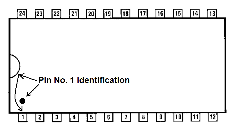
#1 4 years ago

So I am scouring the forums and google for anyone who has had the same issue as mine, and I have not found one yet. So I figured, while I hunt, I would put it out here.

I have reflowed the pins on all display boards, as well as the solenoid driver board. The MPU is an Alltek Board. High voltage section has been tested and is functioning properly. As well, all test points on boards correct. Including Rectifier. Known good boards have been swapped in to no avail. Self test does the same error in incorrect digits. If left on for a while some of the displays will read correctly then go back again, and there is no rhyme or reason. Any help would be greatly appreciated. This thing was a mess when I got it, and still has a lighting issue, that is not connected to the board. As I have used with a known good board.

Evel Knievel Display Issues (resized).jpgEvel Knievel Display Issues (resized).jpg
#2 4 years ago

Some more details about what the displays are doing incorrectly would help.
But judging by the fact your displays should probably be showing zero digits instead of fours in your picture, then you have exactly the same problem as here:

https://pinside.com/pinball/forum/topic/scoring-displays-only-showing-4-5-6-7#post-5420181

#3 4 years ago

Thank You very much for that, I will check that asap. I need to get in some more of the crimp terminals for that size (.100) because I ran out. I missed that forum post. I will post back with results.

#4 4 years ago

Also, yes it is doing just that pretty much. They are only showing 4-5-6-7 generally. I replaced all of the .156 pins and some of the .100 pins but ran out and ordered a couple hundred more which will be here friday, but at least I can pull the pin to check it out, and replace it friday when they come in. Thank you again for the direction.

#5 4 years ago

Did you repin the connector on the MPU? The first digit should always be 0. Looks like you are off by a pin on the digit select wire.

#6 4 years ago

I have the exact same issue on an Eight Ball. I checked the J1 connector, pushed pins in and checked wires but that did not change anything. Is it strictly a repin to fix this or could U20 or another chip be bad on MPU?

#7 4 years ago
Quoted from slghokie:

I have the exact same issue on an Eight Ball. I checked the J1 connector, pushed pins in and checked wires but that did not change anything. Is it strictly a repin to fix this or could U20 or another chip be bad on MPU?

So with your multi-meter set in low resistance mode, do you measure zero ohm continuity from pin 17 at any display connector, to the MPU board on the top leg of resistor R82 (which is near the bottom of the MPU J1 connector)?

#8 4 years ago
Quoted from slghokie:

I have the exact same issue on an Eight Ball. I checked the J1 connector, pushed pins in and checked wires but that did not change anything. Is it strictly a repin to fix this or could U20 or another chip be bad on MPU?

This looks to me like the digit select pins are off by one and need to be shifted over.

#9 4 years ago

Quench I tested this last night: do you measure zero ohm continuity from pin 17 at any display connector, to the MPU board on the top leg of resistor R82 (which is near the bottom of the MPU J1 connector) and with meter on 20 ohm setting I get a reading of .3 Also checked continuity from pin 17 to the resistor and was fine. Logic probe read H.

I also checked the BCD segments at MPU connector

D0 Low
D1 HL pulse
D2 High
D3 HL Pulse

#10 4 years ago
Quoted from slghokie:

I get a reading of .3 Also checked continuity from pin 17 to the resistor and was fine. Logic probe read HL pulse.

Where did you measure this HL pulse? Because below that you said that D2 at the BCD segments of MPU connector measured High.

#11 4 years ago

Sorry @quench, updated the post, the test at resistor was high not high pulse. Just mistyped. Does that indicate that U20 is sending the wrong info?

#12 4 years ago
Quoted from slghokie:

Does that indicate that U20 is sending the wrong info?

Nope. U20 is responsible for selecting display digits. It doesn't control the display BCD data.

The BCD data comes from U10 PIA "port A" pins - these same "port A" signals also share control features with the lamp driver board and the switch matrix.
First thing to do is disconnect both J2 and J3 (switch harnesses) from the MPU board, and also J4 from the lamp driver board. This isolates the U10 "port A" pin solely to the displays.
Does the problem go away?

#13 4 years ago

Quench for mine the problem remains after removing J2/J3 from the MPU and J4 from lamp driver

#14 4 years ago
Quoted from slghokie:

@quench for mine the problem remains after removing J2/J3 from the MPU and J4 from lamp driver

Since that BCD display signal also shares function with the lamp driver board and game switches, are all the lamps and switches behaving correctly?

Grab your multi-meter and set it to resistance mode. With the machine off, black meter lead on ground, use your red meter lead to measure the resistance on both the upper and lower legs of resistors R80, R81, R82 and R83 (next to the lower end of the J1 connector).

#15 4 years ago

@quench the credit/replay switch does not register (I can coin up but never start a game). When I go in switch test it lists 46 which I guess is really 06 for credit switch. Connection from both wires to the connector is good and I replaced the diode.

For the resistors 80-83 the bottom and top legs do not give a reading when checked VS ground.

#16 4 years ago
Quoted from slghokie:

For the resistors 80-83 the bottom and top legs do not give a reading when checked VS ground.

Sounds like you haven't set the resistance range on your meter properly. I measure between 5k and 15k resistance on various boards depending on the brand of PIA chip used. So if you haven't got an auto-ranging meter set it to 20k resistance range and if no luck, then set it on 200k resistance range.

BTW, you should start your own tech thread and post clear pictures of your MPU board.

#17 4 years ago

Quench aha, seems I went way too low with my resistance measurement. If I use 20k I get
Upper
80=3.35
81=3.4
82=4.65
83=3.36

Lower
80=2.17
81=2.21
82=1.41
83=2.17

#18 4 years ago

Here is the MPU, will also do as tech thread

87956805_2931757636877163_6901919394205532160_n (resized).jpg87956805_2931757636877163_6901919394205532160_n (resized).jpg88122891_2931757253543868_8674568717864009728_n (resized).jpg88122891_2931757253543868_8674568717864009728_n (resized).jpg
#19 4 years ago
Quoted from slghokie:

Upper
80=3.35
81=3.4
82=4.65
83=3.36

Lower
80=2.17
81=2.21
82=1.41
83=2.17

Ok, you can see there is a different resistance reading on the problem signal at R82. The problem looks like it's on the board side of that signal, not the MPU J1 connector side.
There are three capacitors on that signal which one might be internally shorting, or the U10 chip itself may have a fault on that signal pin.
That signal goes to the MPU board dip switch block S9 to S16 so the next least invasive test is to make sure all those switches are in the off position to isolate the switches from that signal and redo the resistance checks on the lower legs of resistors R80-83. See if the reading on R82 changes to match the other resistors.
If not pull out the 6821 chip at U10 and again redo the resistance checks on the lower legs of resistors R80-83. If R82 reading is still vastly different the problem will be on one of the capacitors on that signal either C47 or C53. Unsolder one leg of each of these capacitors one at a time to see if the R82 reading changes. Try C53 first then C47.

#20 4 years ago

Quench excellent! I tested with the dips all off, pulled the 6821 and still get the same readings on R82. So I will find my parts board and check on the caps. Not sure if I have any of those caps on hand other than a parts board. Will let you know what happens.

#21 4 years ago

Wow, this forum blew up!! Awesome, I finally got to check it out. I pulled the pins and they looked good, but of course when my new pins finally came in, I repined the connector, and sure enough, displays great. So all good on the displays. I went ahead and repined the other connectors so we are good to go. But, I might as well throw out the last problem as it has been driving me nuts.

I have an alltek MPU and the rest of the boards are original. All of my controlled lamps are on at all times. Well, a picture says a thousand words, so I figure a video says a million theoretically... lol possibly a bit of help getting me out of my head and maybe simplify. I cant seem to find anything in the schematics that is common to all of them, other than possibly a ground, but I cant find the bad ground. I have swapped all the boards with known working boards to no avail except for the transformer / rectifier. Again, thank you to everyone here that is so helpful on stumped issues. Also Game Over High Game To Date and Tilt flash during game play...! Here is a quick video to get an idea...

#22 4 years ago

@quench Thanks again for all your help!. Well I replaced C47 and C53 and the display issue remains. It did fix the credit/replay button so it will start a game now. I did recheck with removing the connectors but still same display issue and resistance is still higher on R82 than the others.

You mentioned there was a 3rd capacitor to check, which one is it?

#23 4 years ago
Quoted from wildinindiana:

All of my controlled lamps are on at all times. Well, a picture says a thousand words, so I figure a video says a million theoretically...

Please grab your multi-meter and set it to DC voltage.
Measure the voltages at the following chip pins on the lamp driver board during attract mode and report back:
U1 pin 1
U1 pin 2
U1 pin 3
U1 pin 21
U1 pin 22
U1 pin 23
U2 pin 23
U3 pin 23
U4 pin 23

The following image shows how to find pin 1 on the chips. Look for the notch on the end and/or a dot at a corner pin. Pins are numbered anti-clockwise.

4514_PinNumbering.gif4514_PinNumbering.gif

#24 4 years ago
Quoted from slghokie:

Well I replaced C47 and C53 and the display issue remains. It did fix the credit/replay button so it will start a game now.

Not sure how but capacitors C47 and C53 have no correlation to the start button.
Has the resistance reading on the lower leg of R82 changed from before?

Quoted from slghokie:

You mentioned there was a 3rd capacitor to check, which one is it?

Ignore that. When I mentioned switching off dip switches S9 to S16, that disconnected any other capacitors.

What happens if you swap U10 and U11? (they are the same spec part)

Find resistors R35 to R38 (they're under the red S33 switch at the top of the board). What do you measure across them? (i.e. meter leads on each leg). R38 is on the PA6 signal, if it measures a lower than the other three resistors, unsolder one leg and lift that leg from the board. Remeasure the resistance across that R38 resistor and report back. Those four resistors are 3.3k ohm resistors.

While you have the board removed from the game take it outdoors in daylight but out of direct sunlight and take some high resolution pictures front and back. When you attach the images here, make sure you select "Original size (no rescaling)" - I need to see as much detail as possible.

#25 4 years ago

Quench I measured R38 and it was (20k meeter setting) 3.53 while the surrounding ones were more like 2.1. I checked another board and all the same resistors were all 3.X. Both boards were -35 versions. I did not lift the leg since it was not lower.

I also checked the continuity from the bottom of R38 to pin 8 on U10. Did not have it at first. Pulled this chip and checked. Had continuity to the socket but not when the chip was in. Added a little solder to leg 8 of the chip and now have continuity from bottom of R38 to pin 8 chip leg and socket+board. However still have 44 on the display.

#26 4 years ago
Quoted from slghokie:

Upper 82=4.65
Lower 82=1.41

Umm, I just reread post #17 and realised I missed something. Resistor R82 is 1.2k ohms spec. But according to your R82 readings, yours measured 3.24k (4.65k - 1.41k). Your R80, 81 and R83 (which I didn't quote) gave good 1.2k readings.

Please confirm the reading across R82 (place meter leads on each leg).

Hook up your logic probe. In attract mode, what does it indicate on the PA6 signal originating at U10 pin 8, then the bottom leg of resistor R38, bottom leg of R82, top leg of R82 and top leg of C47?

Quoted from slghokie:

I also checked the continuity from the bottom of R38 to pin 8 on U10. Did not have it at first. Pulled this chip and checked. Had continuity to the socket but not when the chip was in. Added a little solder to leg 8 of the chip and now have continuity from bottom of R38 to pin 8 chip leg and socket+board.

That tells me the U10 socket has loose receptors. Lately I have been using this trick to check socket receptors. Using a new faulty chip, I bend a single leg outwards 90 degrees and try placing the bent leg in each location of a socket looking for receptors that don't grab the leg. I've already found a number of bad sockets with one or more loose receptors doing this.

Quoted from slghokie:

I measured R38 and it was (20k meeter setting) 3.53

Well, that's already out of spec and note that measurement was in circuit. That resistor is a 5% tolerance part, so at 3.3k spec, a reading above 3.465k is out of spec. I suggest desoldering the lower leg and lifting it out of the board to measure the resistance across it out of circuit.

#27 4 years ago

Quench R82 now reads 1.2 so that seems good now.

Will have to check the rest of the socket receptors

R38 measures 3.53 in circuit and 3.50 out of circuit. When I desoldered the leg it mostly came off. The resistors around it read 2.1. So I guess I need a new 2.1k ohm resistor to continue or is it supposed to be 3.3k ohm (based on schematic)? I guess the leg could have been faulty

#28 4 years ago
Quoted from slghokie:

So I guess I need a new 2.1k ohm resistor to continue or is it supposed to be 3.3k ohm (based on schematic)? is it supposed to be 3.3k ohm (based on schematic)?

It's a 3.3k ohm resistor. The other resistors are reading lower because there's other components in circuit putting parallel resistance across them which this signal is missing somewhere.

Do the logic probe checks first before checking the socket receptors.

#29 4 years ago

So, Quench I went to boot the EK and everything works great. Its actually very frustrating. I would have rather it mess up again so I could fix it, but apparently its not going to happen, at least not for now. Thank everyone for their help and Happy Gaming!!!

#30 4 years ago
Quoted from wildinindiana:

So, Quench I went to boot the EK and everything works great. Its actually very frustrating. I would have rather it mess up again so I could fix it, but apparently its not going to happen, at least not for now.

I didn't mention it above because I was hoping the voltage readings would confirm but I suspect you have a suspect connection on the "Lamp Strobe #1" signal from the MPU board J1 pin 11 to the lamp driver board at J4 pin 13 (Orange-White wire). Note the pin numbers on the lamp driver board are upside down - pin 1 is at the bottom and counts upwards.
An open circuit on that signal can cause a bunch of lamps to come on when they shouldn't. If the problem comes back, re-terminate the crimp terminals with new ones on both ends.

#31 4 years ago

@quench Thank you so much for your help diagnosing all this!

Since the leg came off R38 I replaced it with a new resistor (not from part board). Measurement across now is 3.3k.

For the logic probe measurements:
U10 pin 8= HL Pulse
Bottom R38= H
Bottom R82= H
Top R82= H
Top C47= H
Bottom of C47 = L
Resistance across R82 is 1.2k

Could it be that the C47 I replaced was also bad? It came off the parts board.

Here are the daylight photos of the board

#32 4 years ago

For some reaon it wont let me select the original size so I did high res which it allowed.

DSC06292.JPGDSC06292.JPGDSC06293 - Copy.JPGDSC06293 - Copy.JPG
#33 4 years ago
Quoted from slghokie:

U10 pin 8= HL Pulse
Bottom R38= H
Bottom R82= H
Top R82= H
Top C47= H

Cheers. The logic probe readings show that you've got activity on U10 pin 8 which is good. There's two traces running from that pin, one goes to the dip switch S9-S16 block then up to the bottom leg of R38, the other trace runs to the top leg of C47. Both of these showed no activity with the signal sitting high (because R38 is a pull-up resistor).

You have a bad pin receptor connection at that U10 socket on pin 8.

You can try the pin receptor test I previously mentioned - do all locations on that socket.

If you don't want to change the socket right now, pull U10 out. Very carefully pry off the plastic part of the U10 socket without damaging the PCB - this will expose all the pin receptors. Compare the one at pin 8 to the others. Carefully bend the receptor back into shape (and any other suspect ones) and then put the socket cover back on including the U10 chip and try it in the game.

See the example pictures here - if you zoom in on the third picture look at the receptor at pin 4 which you can see is squashed in compared to the other receptors:
https://pinside.com/pinball/forum/topic/as-2518-35-continuously-rebooting#post-5400784

#34 4 years ago

@quench Great news! I checked each socket on U10 and did the solder trick on each leg, popped it back in and boom....got 00. Could have been a combo of the receptor and the pins were marked up from use. For anyone reading after the fact, I put a little solder on each leg, just enough to coat it and make the leg marginally thicker side to side. That kept me from replacing a 40 pin socket and fixed my display issue.

Also fixed the flippers and all features work. Got some janky light sockets and switch adjustments, but should be smooth from here out.

Thank you again Quench, your help and guidance was the key to getting this Eight Ball over the finish line.

74224159_2944629435589983_4002192397772521472_n (resized).jpg74224159_2944629435589983_4002192397772521472_n (resized).jpg88257487_2944630082256585_1696798749512171520_n (resized).jpg88257487_2944630082256585_1696798749512171520_n (resized).jpg
Promoted items from Pinside Marketplace and Pinside Shops!
From: $ 150.00
From: $ 10.00
Playfield - Protection
UpKick Pinball
 
$ 69.00
4,000 (OBO)
Machine - For Sale
Queen Creek, AZ
$ 12.00
Playfield - Toys/Add-ons
UpKick Pinball
 
$ 99.00
$ 69.00
Gameroom - Decorations
Pinball Pimp
 
From: $ 14.00
Electronics
Third Coast Pinball
 
$ 179.00
$ 69.00
Gameroom - Decorations
Pinball Pimp
 
$ 18.95
Eproms
Pinballrom
 
$ 179.00
$ 29.99
Cabinet - Shooter Rods
Pinball Shark
 
From: $ 3.50
Playfield - Other
Rocket City Pinball
 
2,500
Machine - For Sale
Tehachapi, CA
$ 69.00
Gameroom - Decorations
Pinball Pimp
 
Hey modders!
Your shop name here

Reply

Wanna join the discussion? Please sign in to reply to this topic.

Hey there! Welcome to Pinside!

Donate to Pinside

Great to see you're enjoying Pinside! Did you know Pinside is able to run without any 3rd-party banners or ads, thanks to the support from our visitors? Please consider a donation to Pinside and get anext to your username to show for it! Or better yet, subscribe to Pinside+!


This page was printed from https://pinside.com/pinball/forum/topic/evel-knievel-display-issues-all-incorrect-digits?hl=slghokie and we tried optimising it for printing. Some page elements may have been deliberately hidden.

Scan the QR code on the left to jump to the URL this document was printed from.