(Topic ID: 159104)

EM Pinball Circuits-Basics to not-so-basic

By SteveFury

7 years ago


Topic Heartbeat

Topic Stats

  • 132 posts
  • 50 Pinsiders participating
  • Latest reply 2 years ago by RetroDad65
  • Topic is favorited by 329 Pinsiders
  • Topic is sticky in its sub-forum

You

Linked Games

No games have been linked to this topic.

    Topic Gallery

    View topic image gallery

    0Fast-Draw-Work-23 (resized).jpg
    0Fast-Draw-Work-22 (resized).jpg
    0Shangri-La-Work-33.jpg
    schematic (resized).jpg
    Schematic scan 2 (resized).jpg
    Schematic scan 1 (resized).jpg
    Jack Layout.pdf (PDF preview)
    cam timing.pdf (PDF preview)
    Lug_ID.png
    Flipper_Strength_Range.png
    Flipper_Ckt.gif
    Flux_Lines.gif
    20161106_105952_resized (resized).jpg
    Special_1_lite_tst_c_(resized).png
    Special_1_lite_tst_b_(resized).png
    Special_1_lite_tst_a_(resized).png
    There are 132 posts in this topic. You are on page 2 of 3.
    #51 7 years ago

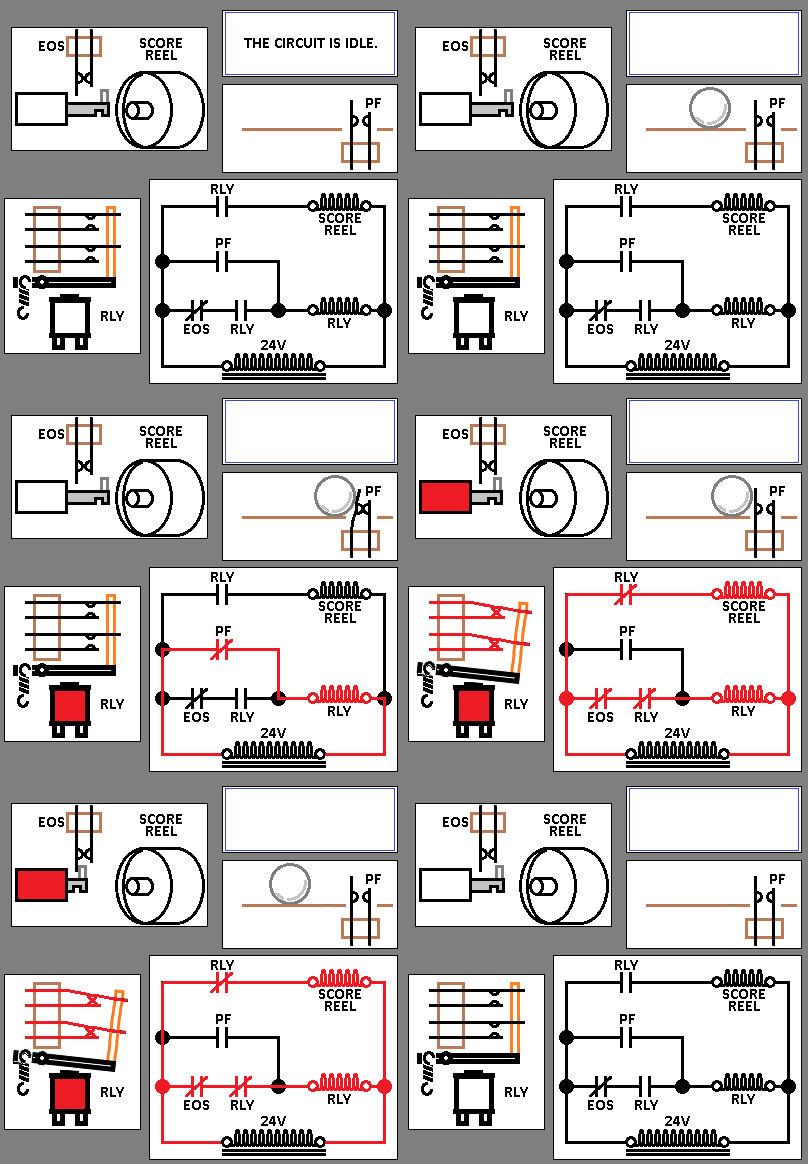
    Let's find the parts of the 10 point End of Stroke circuit on a schematic.

    We know a playfield switch does not connect directly to the score reel but instead connects to a 10 point relay.
    That will be the focus of my first search on the schematic. The 10 point relay is found on the top right corner:
    10p1_(resized).PNG10p1_(resized).PNG


    Let's find the circuit that will pull in the relay. We locate the playfield switch that operates it and I drew a red line through it:
    PFS_(resized).pngPFS_(resized).png


    One thing to note, is the schematic says "(3) STAND UP SWS". It means they've only drawn one playfield switch but there's three in the circuit. How are the others drawn? Would they be in series or parallel? Since we know the ball will be hitting "that switch or that switch or that switch" we can know they will be in parallel:
    3Sws_(resized).PNG3Sws_(resized).PNG


    We also know the relay will have a locking circuit so I am looking for a switch that is in-series with the relay, and is also named the same as the relay:
    10ps_(resized).PNG10ps_(resized).PNG
    The circuit path can be mapped out:
    10pSeries_(resized).png10pSeries_(resized).png
    We can see it passes through some other switches labeled "10 point D.U.E.O.S switches". Williams call their score reels "Drum units" so those are the 10 point score reels for players 1-4. Since they are all arranged in series we know "that switch and that switch and that switch" needs to be closed for the current to flow through the relay.

    In review, one of the (3) playfield switches will momentarily close, pulling in the relay and the relay will be held on by its own switch.

    We know the score reel (Drum Unit) will be part of this circuit so I locate it on the schematic.


    Here it is and I've drawn a line through its 10 point circuit.
    We can see current will flow through the 10 point relay, through the Player unit before passing through the score reel solenoid. When the 10 point relay closes then the score reel solenoid will go on:
    10pDU_(resized).png10pDU_(resized).png

    We know, based on the operation of my previous EOS circuit the plunger will pull in, the EOS switch will open to drop off the relay and thus turning the score reel solenoid back off.

    Study for fun:
    *What would happen if any one of those four 10PT D.U.E.O.S. switches break and is no longer able to close?
    *What will happen if the 10 point relay goes on but the score reel jams and all four 10PT D.U.E.O.S. switches remain closed? Why?

    Here's a schematic preservation tip:
    You can scan your schematic into a computer image file by either using your own scanner or have a neighborhood print shop do it for you. Since schematics are so large they don't fit on most scanners but you can scan the sections at a time. You can use most editing software (Even MS PAINT) to re-assemble them into one image.

    It takes a bit of effort to scan and assemble the images into one- but you only need to do it once and use that scan forever, even burn it onto a CD or thumb drive to store in your machine for future use. That way you can keep the original in the machine as they are usually kept. When you need to fix your machine then you won't be unfolding/folding/manipulating the original document but using the image file instead.

    You can certainly use your cellphone but the results won't be as good as an actual scan.

    One -HUGE- benefit is you can create copies of your scans and mark it up with notes, something you shouldn't do with the original.
    Gottlieb for example uses letter assignments not names for most coils and switches and uses references for score motor timing. I have an original scan, and another scan with the components re-labeled which makes the understanding/analysis much easier.

    #52 7 years ago

    I'm going to step out and take a big leap.
    Suppose you have a Gottlieb 4 player game that is having trouble counting the balls and/or keeping track of the players. In any case it is helpful to know how the circuits are supposed to work in the first place. I plan to go through the schematic and show a logical process to figure it out. I don't intend it to be a Gottlieb player unit tutorial but instead to show a logical learning method.

    I choose that process simply because it is very complicated as many EM pinball circuits are. It is little more than a collection of the circuits already covered. Arranged in clever ways.

    If you're unfamiliar with a Gottlieb 4 player game then you can fast forward on this video I found (not my video) to 2:18 and watch how it switches balls/players (Watch the back glass):


    Those are our observations but we don't yet understand what is happening inside the machine to make it so. We'll find out over the next few days (As my time permits).

    #53 7 years ago

    If you are trying to learn how a complex circuit is supposed to work and you try to consider all the circuits at the same time it is certainly overwhelming. It is always easier to simplify things as much as possible.

    We're looking at a Gottlieb 4 player game.
    Our goal is to decipher the sequence of events when it's switching players and balls. The schematic is about 3 feet long and more than a foot wide. We must determine where to begin first. At this point all we know is the game makes clicking noises and flashes lights as it moves from from ball to ball and player to player.

    Lighting circuits are usually the simplest to understand so that's a great place to begin.

    On this particular game, the score reel back lighting indicates which player is "up".

    I look around the schematic to locate the score reel lights:
    Score_Reel_Light_Ckt_(resized).PNGScore_Reel_Light_Ckt_(resized).PNG
    We can see the simple circuit. Each score reel has 5 lights wired in parallel and controlled buy two switches so when either switch closes then the lights go on. One switch on each player is labled either "Last Ball Relay" or "Game Over Relay".
    We are not interested in the "Last Ball Relay" or "Game Over Relay" so it's pretty safe to ignore those.

    The remaining switch is labeled "P1F", "P2F","P3F" and "P4F". We need to find out what those switches are. Looking around the schematic, no documentation about those switches can be found.
    Frustrating for sure.

    I check all the other generic Gottlieb documentation and found this as part of their "Installation Procedures and Game Operating Instructions" booklet:
    Player_Cam_Docs_(resized).PNGPlayer_Cam_Docs_(resized).PNG
    Here we found "P1F", "P2F","P3F" and "P4F"
    We can see that switch:
    "P1F" is operated by the 1st cam.
    "P2F" is operated by the 2nd cam.
    "P3F" is operated by the 3rd cam.
    "P4F" is operated by the 4th cam.

    That image is part of this larger page which shows a series of cams. It will be helpful to learn how those cams are arranged:
    Player_Cam_Docs_2_(resized).PNGPlayer_Cam_Docs_2_(resized).PNG
    Looking at the cam lobes, we see that:
    *Each cam has 5 lobes.
    *Each cams are identical, but rotated to a degree one to the next.
    *Because they are rotated one to another, the lobes will change the state of the switches in sequence.

    One piece of our puzzle is solved, what the P1F through P4F switches are and the cams that operate them.

    Looking again at the lighting circuits, we locate the ball in play lites:
    Player_lights_(resized).PNGPlayer_lights_(resized).PNG

    We can also see some of the Double bonus circuitry in the schematic. That will only muck up and confuse our thought process so we can ignore it. We're only focused to know how the Ball in Play lites are switched.

    We can see a stepper symbol on the left (Review post #14 if needed).

    Schematics are drawn on the 1st player with the 1st ball ready to shoot and then the machine unplugged. -ALWAYS- keep that in mind.

    Keeping that quote in mind, we know player 1 ball 1 is indicated on the stepper.

    We can notice on the schematic, that the stepper:
    *Will need to make 4 more steps to make it to ball 2.
    *Will need to make 4 more steps to make it to ball 3.
    *Will need to make 4 more steps to make it to ball 4.
    *Will need to make 4 more steps to make it to ball 5 (Then game over).

    We know the stepper rotor will rotate with the 4 cams previously discovered because they are connected by a common shaft.

    #54 7 years ago

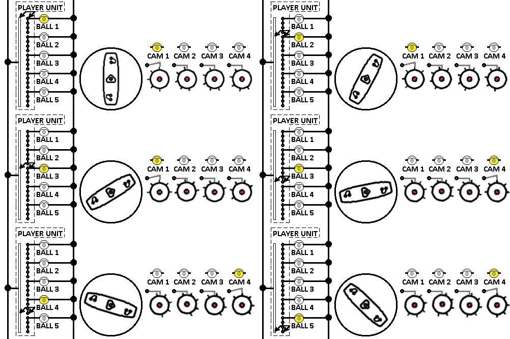
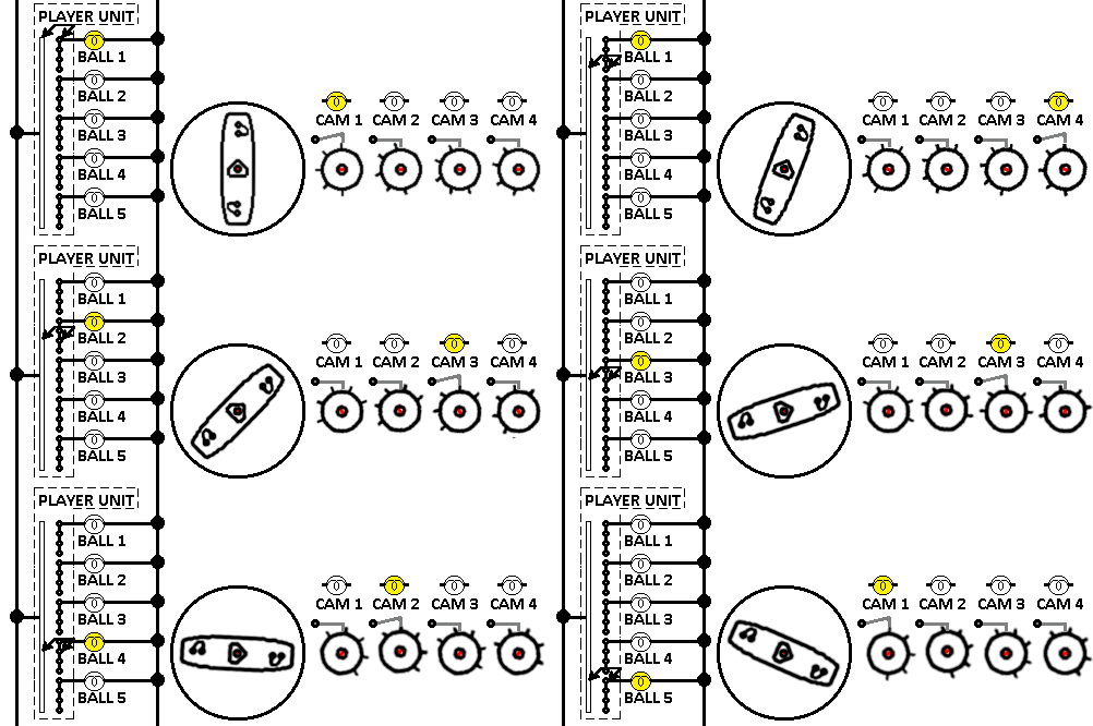
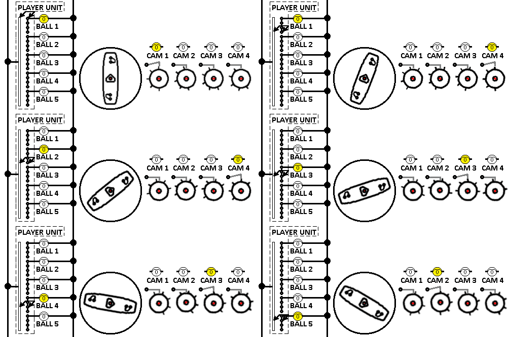
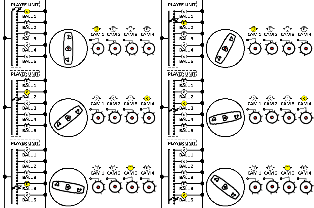
    We also discovered the rotor takes 4 steps to make it to the next ball number, and the 4 cams operate the player up lites in order. Therefore we can picture this 4 player 5 ball sequence.
    Keep in mind the cam number correlates to the player number:
    4PGame-fx.gif4PGame-fx.gif
    How about a 1 player 5 ball game? We know it will need to operate as follows.
    The animation will pause for ball play, then step to the next player:
    1PGame-fx.gif1PGame-fx.gif
    2 player 5 ball:
    2PGame-fx.gif2PGame-fx.gif
    3 player 5 ball:
    3PGame-fx.gif3PGame-fx.gif

    So far we've learned a logical method to learn something from a schematic, and that sometimes other documentation is needed.
    We learned that a Player Unit switches the game from player to player and ball to ball.
    We've also learned how stepper units can be used along with cams to achieve something (In this case the switching of indicator lights).

    Generally when I am analyzing a segment of circuit that contains many segments, I don't always have a chance to make physical notes. I often need to keep the current status of different relays, steppers etc as a mental note for each circuit. Then consider how various elements change for an event.
    I find that to be the biggest challenge of all when learning how a circuit works from a schematic. I find with most things the more you practice the easier and more natural it gets.

    I plan to move on to a method to analyze other parts of a schematic, the Player stepping circuit as it pertains to what we discovered here.

    Please let me know whether the flow of this still seems OK.

    #55 7 years ago

    Are folks able to follow the above posts?

    #56 7 years ago
    Quoted from SteveFury:

    Are folks able to follow the above posts?

    Love the animations keep em coming

    --Jeff

    #57 7 years ago

    yup, flowin right along! thanks

    #58 7 years ago

    Yes, it is good for me.

    #59 7 years ago

    Thanks for the feedback.
    So far we know the player unit on this particular game switches the player and ball count lights. We know that something is causing it to switch (pulse). Here's a method to discover how it's being operated.

    The player unit will likely be stepped by a solenoid, as most steppers are. Since this solenoid is a main part of the stepper then by locating it you can find the things that operate it. Looking around the schematic I find the "Add Player Unit" solenoid, middle left:
    PPC01_(resized).PNGPPC01_(resized).PNG
    Sure enough it is surrounded and wired to some pretty complicated looking stuff. Different parts of the circuitry does different things. Remember we are only looking to discover how the game switches between players and ball numbers so we can eliminate the other circuit parts that make it confusing.
    This schematic is the kind that assigns letters to switches instead of naming them which can make it a bit more difficult.

    So we can pick a random point to begin identifying what the various circuits do. You'll find clues most of the time based on the name of devices. For example find the AX switches on the top right of the schematic. To find out what the AX switches may be, the answer is in the legend:
    Legend_(resized).PNGLegend_(resized).PNG
    We can see the AX is the "Reset Control Relay". Hmm. Looking further down its connecting wire I see it goes through the player unit disk (Positions 20 & 21) and onto Z1 and Z2 relays. I also see the line goes down to the "S" relay. Looking at the legend I discover that is the "Start" relay.


    I consider these devices for a moment:

    A reset control relay along with a Start relay probably doesn't have much to do with changing players. Sounds like those may be used to start the game so I can eliminate those.
    I will picture the image below in my mind as I continue with the circuit:
    PPC02_(resized).PNGPPC02_(resized).PNG
    It looks a bit less cluttered?

    Inspecting what components are left, we see a mess of switches near the top, a "coin unit" and a "Player unit" stepper rotor switches and a 3-5 ball adjust jack. We also see some familiar switches "P2G",P3G" and "P4G" switches that we know are operated by cams on the player unit.

    The only devices left that don't appear to be switching players is likely the upper cluster of switches. I say that because I see a whole bunch of reset switches and those Z1 and Z2 relays that I previously eliminated.

    If I examine the block of switches below, I notice there are two definite ends to that mystery cluster. One end connects directly to the "Add Player Unit" solenoid and the opposite end connects to the other stuff below it. Like this (See the arrows):
    PPC04_(resized).pngPPC04_(resized).png
    We eliminate the clutter in the green box but look what happens to the circuit when I eliminate the clutter:
    PPC05_(resized).PNGPPC05_(resized).PNG
    The circuit will not work because nothing connects to one end of the player unit solenoid.
    More, the previous circuit is isn't complete either.

    I bet I can find a circuit path in the cluster I've just eliminated. There's actually a few circuit paths through that mess. Here's one path that goes through the two closed Z1 and Z2 relay switches:
    PPC06_(resized).pngPPC06_(resized).png
    Knowing the cluster is likely not part of my player switching and ball count circuit, and the path only completes through the two Z relays then I can probably remove the messy cluster and connect it like this:
    PPC07C_(resized).pngPPC07C_(resized).png
    I did a bit of clean-up for sake of the website but it's really the same as the previously cluttered copy. I left the 3-5 ball adjustment stuff on the diagram because it may, more or less be part of my player switching and ball count circuit.

    You can see how a previously overwhelming diagram becomes something much more manageable.
    If, in the analysis something doesn't make any sense then we can revisit those circuits we decided to ignore and see if it works out.

    You won't normally be able to re-draw schematics like this when you are troubleshooting problems but you can learn how to compartmentalize segments of circuits to effectively do the same thing.

    That is entirely the point I am making in this post. That you can see the schematic as it is printed with all the clutter but you read what is the last cleaned-up image I posted.

    (continued soon)

    #60 7 years ago

    Well Steve, I have to say you have moved from Basics to not-so-basic...
    Good stuff.

    #61 7 years ago

    Hi Steve, Chris, +
    lets hope for "Newbies" to give feedback. I do and I have seen other pinsiders giving the tip "look-up in this "basics to not so basic" topic. So "one post - one problem / thema" is helpful / good.

    I enjoy post-53, post-54 (great animation) ... post-59. (((I feel a bit uncomfortable asking))) I would like to have (new post) post-54 AND post-59 connected - HOW does the COIN-Unit influence the X-times stepping the "Add-Player-Unit" ? - and as the Player-Unit is stepped - what do P2G, P3G, P4G have to do in this circuitry ? How to understand the drawing of Coin-Unit - How are connections set in this Unit when we play a 1-player-game ?
    With some added information: When a pinsider wants to help on a Gottlieb "stepping through players / balls" -> a simple "Look-up 'basics to not so basic - posts 54 to 59, ??-??' " will be a great help. Greetings Rolf

    #62 7 years ago

    This is a great resource for people new to EM circuitry (or even electrical theory in general). I'll be pointing people this way soon. Thanks for taking the time to post these animations and schematic snippets. I've tried explaining basic electrical theory and schematic reading/troubleshooting concepts on my show, but it is difficult for some folks to learn or follow along with an audio show.

    You hit two out of the three learning styles (if you fudge the definition of 'kinetic' a bit to reference your animations), and I hope everyone just getting into EM repair and maintenance will review. Thanks again for putting this together.

    #63 7 years ago

    Thanks for the encouragement. I should be able to continue shortly.
    The coin unit is a part of player switching so we will need to go over that.

    I am saying "we" because my goal in this series is to offer the basics and raise the understanding so folks can read their own schematics in a logical way and make their own diagnostics. It's not my intent to demonstrate how a particular circuit works (although it necessarily happens) but rather to outline a method to figure it out.

    If I can repeat a method many times across many sub-circuits then I am hoping folks can notice the common patterns in the process of diagnosis. I am actually applying the same diagstic steps over and over.

    The feedback is really appreciated because it lets me know if my presentation is effective or not.

    #64 7 years ago

    Sorry, I'll be re-posting this today for errors.

    #65 7 years ago
    Quoted from bingopodcast:

    I'll be pointing people this way soon.

    I've been pointed. Thanks BingoPodcast.

    AND THANK YOU STEVEFURY!!! This is an incredible resource. Thank you for putting this together. I just found this, but I'll be pouring over this soon. I'm an artist, not a tech. I bumbled my way through my first Electro-Mechanical restore recently, but still feel like I could understand circuitry a lot better. I have a feeling this thread will be my gateway into better understanding of all things electrical.

    Grateful,
    Ryan Claytor
    Elephant Eater Comics
    www.ElephantEater.com

    #66 7 years ago

    I've changed the circuit appearance again, to keep it original as possible while d-emphasizing the unrelated clutter, as we might consider it while studying the circuit design. You can always refer to the clean version in post #59 if you wish.
    PPC08_(resized).pngPPC08_(resized).png
    We can find the "ADD PLAYER UNIT" solenoid attached to the left power bus. Since current will always be trying to flow from one bus to the other, I will begin my investigation with what ever associated devices begin on the right bus.

    The first (break) switch is labeled "I". Looking at my legend I see the switch "I" is part of the "Extra Ball Relay" as shown on the legend:
    Legend_(resized).PNGLegend_(resized).PNG
    I was going to brush past that switch, but I had discovered it uses a new kind of switch to mention. Let's go through the extra ball circuit and see what we find.

    The Extra ball relay coil "I" is found among some fairly confusing circuits:
    ExtBallCkt_(resized).PNGExtBallCkt_(resized).PNG
    I think the bend in the connection to the "G" switch is what makes it confusing, so I can recognize what is not relevant to our extra ball circuit and ignore it. Like this... now I have a better chance to understand it:
    ExtBallCkt-FD.PNGExtBallCkt-FD.PNG
    I see the isolated diagram and try to discover the things which look familiar.

    The relay coil name is "I" and I also see an "I" switch in series with it.... So I consider it may be its locking switch. I can follow the line beginning on the right side, through the runway switch to the "I" switch.

    I have just verified that line is the relay locking circuit because once "I" closes the relay will be locked on until the "Runway SW" opens. The runway switch exists in the shooter lane so it changes state when the ball is shot down the lane.

    If there's a lock then something must trigger the lock.

    Always look for the trigger connection to be wired between the locking switch and the relay coil. The locking switch will have the same name as the relay coil.

    That leaves the other line.

    Since the coil is connected to the left bus I look for the first device on the right bus. I'm skipping the switches G, Motor 3E and the J switch.

    That leaves switch 6B. We look at the legend and find this:
    Bank.PNGBank.PNG
    We see it is the "Sequence completed relay" and it has no coil. What the heck is a relay without a coil?

    Most pinballs have sequences which the player must complete before they get a reward like an extra ball or special etc. Such as getting the ball through lane A, and lane B and lane C lites the special.
    Getting the ball through those lanes activate its associated relays.

    Those series relays will be a latching type relay.
    The latching type relay has a mechanical arm which interacts with the armature. The arm/latch holds the armature down after power is cut off from its coil.
    The pinball in play can roll over... And then back off of the lane switch and a latching arm holds the relay arm "on" but the coil cuts off when the ball rolls off the lane switch.
    IE: The ball rolls through the "A" lane and the "A" lane remains lit after the ball rolls through.

    The A+B+C=special series mechanisms can be designed a couple different ways. Electrically or physically.

    Electrically: the Series circuit.
    An electronic series circuit was cheaper and easier to manufacture if the relays and/or series switches were on devices located in different parts of the pinball machine.
    Remember switches in series can be thought of as "This switch and that switch and that switch" will cause something to happen (See post#3 if needed).

    Physically: The series mechanism
    It was cheaper and easier to manufacture a physically operated series mechanism if a row of relays were in close proximity to each another. In that case the manufacturer would install the relay minus the coil.
    Usually a long row of relays are mounted on a common frame and the entire row is reset by one big (or two) solenoids. Sometimes relays in the row are reset by a player operated arm or motor.

    Instead of the series relay armature being magnetically operated by a coil, it is physically operated by a mechanical arm or bar which spans across several coils.

    When all the associated relays are latched then the series relay arm is pulled down by a spring or other device. Like the animation below. Notice the lite only illuminates when all 3 of the coiled latching relays are down (Latches not shown). The lite could be a special lite, extra ball lite etc:
    ColLessRly.gifColLessRly.gif
    I drew the above animation using normal relays to illustrate the mechanical linkage in a series configuration. A typical latching relay operates closer to the animation below:
    LatchinRlyAnim.gifLatchinRlyAnim.gif
    Here is an image of a series relay bank.
    You can easily recognize the "6B" series relay because it is missing both the coil and the latching arm (yellow). There is a metal bar which spans across the other coiled relay armatures (blue), and the bar is welded to the armature of the series relay (red):
    Bank.jpgBank.jpg

    We return back to our ball and player counting circuit. We've identified what the first switch does.
    We remember the fact in red as we figure out how it works:
    PPC09.pngPPC09.png

    #67 7 years ago

    Continuing with our player up and ball in play project, the next switch to look at from the right is the "U" switch.

    We can look on the legend from the previous post and see it is part of the 1st ball relay.
    We should notice the "U" switch is drawn open so it will not allow the current to flow through it. We should investigate what that switch is because it is an open circuit.

    I was also going to brush over that circuit but, like the previous post there's some important points to know.

    We locate the "U" first ball relay coil on the schematic, middle coil:
    Uckt-or.PNGUckt-or.PNG
    We can isolate the relevant circuit as before:
    Uckt.PNGUckt.PNG
    We see the coil is connected to the left bus so I first consider the associated switch furthest to the right.
    We see a strange looking "H" switch. It looks like a pair of switches with an arrow pointing between them.
    The arrow indicates that it's a make-break switch. On the animation below, both circuits are the same, but drawn a little differently. The push button switch could be a switch on a relay, roll over switch, score motor etc:
    MB2.gifMB2.gif

    The make-break switch is labeled as on the "H" device and the legend tells us that's the Tilt Hold relay.

    The "H" switch (and another switch in this circuit) will cause a lot of confusion unless something is well understood.
    The state of the machine when schematic was drawn is on the first ball for player one, sitting in the shooter lane, and then the machine is unplugged.

    You must consider what ever (non-latching) relay was previously on... Went off when the machine was unplugged. Because of that the state of their switches will be drawn opposite on the schematic

    Does that make sense? That's a very important thing to keep in mind or else it will mess you up!

    The "H" Tilt Hold relay is an example. The Tilt Hold relay goes on and only drops back off when the machine goes into a tilted condition. Therefore it is normally always on during normal game play.

    Further down the line we come across the "R" switch. The legend says it is part of the Hold relay. That too is another always-on relay so it should also be considered to be drawn in its normally opposite state.

    You will never be able to understand the operation of this circuit without that consideration!

    So when we try to analyze this circuit, we must picture it like this:
    U-Fixed.pngU-Fixed.png
    The next switches in the line is the "N" and "M" switches. We notice the two switches are wired in parallel so activating either the "N" or the "M" switch will complete the circuit. The legend shows the N switch to be on the 10 point relay, and the M to be on the 100 point relay.

    We have already looked at the 10 or 100 point relay back in post 50:
    EOS_2.gifEOS_2.gif
    Examining our circuit we can understand that as soon as the ball hits a 10 or 100 playfield switch then relay coil "U" will pull in (red line). We notice a switch named the same as the coil "U" so we know that's in the locking circuit. Following that line we see closed switches on the AX and the MOTOR3C. I drew the locking circuit in green:
    U-Fixed-lines.gifU-Fixed-lines.gif
    We have learned that our mysterious "U" switch on our player up/ball count circuit will close when the pinball hits a 10 or 100 playfield switch, and it will open again when the game is reset (The AX relay will pull in)

    That's the second identified switch:
    PPC10.pngPPC10.png
    We'll keep the function of those switches in mind as we look at the rest of the circuit.

    #68 7 years ago

    Steve, thank you for sharing your wisdom. I don't consider myself a complete noob, but this is really opening my eyes on reading the schematics.
    1) I have a question, in post 66 you are looking at the switches starting on the right bus, but you immediately skipped G, Motor 3E and the J switch. I assume you skipped them based on the legend, but you didn't say why you skipped them. When you say start on the right bus, then skip the first 3 items, it's a little confusing.
    2) Also you are talking about being able to "declutter" the print as you work on a specific problem. This is a great reason for scanning it in the computer as you suggested, you can make a working copy that you can highlight or "paint out" the sections not relevant to the problem you are working on.
    3) The other thing i noticed, is earlier in post 51 you did "study for fun", and asked a couple of questions. It would be nice if a couple of posts later you gave the answer, so people know if they are figuring it out correctly.
    4) You said that the schematics are drawn 1 player, ball 1 in shooter lane, then unplugged. I assume that is the same for all manufacturers, Is that indicated on the schematic anywhere, or is it just something you are supposed to know? Please keep up the good work.

    #69 7 years ago

    Great topic thread.
    Now I just need one covering how best to clean or adjust
    those GTB score motor switches
    that are buried on the bottom cam & inside switch stacks.

    #70 7 years ago

    Hi Insane.
    Thanks for the feedback it's great to hear from folks, especially those new to this. Without feedback I have no way to know if the methods I'm using are effective or not.

    1) Some of these sub-circuits (Circuits off of the main player up/ball count circuit) have deeper sub-circuits and delving into them will get too distracted from the main goal of the player up/ball counting circuit.

    I was originally just going to post the red "Opens for extra ball" on the schematic as a given fact without explanation.
    I looked into that sub-circuit before hand and found a mysterious coil-less relay that I felt needed explanation.
    So when I came to G, Motor 3E and the J switch those are even deeper circuits within the sub-circuit and I didn't want to go too far off the path.

    If you're reading a schematic to fix a broken game, you can often see the name of a switch and make a guess of how it works if the name of it is plain enough. Some circuits like the "Hold" is found in almost every game and when you get to see them enough they become self-explanatory.

    Guessing a switch's operation based on its name can speed up the time involved to read the schematic. But it can sometimes be misleading and the guess can prove to be wrong. If a circuit doesn't make sense then I might revisit those guessed circuits.

    I'll be posting a given state of certain switches again for other circuits for that reason. Such as the switches which are part of the game reset.
    2) Yes, exactly. All these schematics I'm using had been scanned years ago. I've made copies of the main file scan, marked them all up for different things then deleted the altered files when done with them. The frail original paper schematics would have been damaged long ago, if not for scanning once then keeping them with the machine again.
    I'm using MS Paint to draw out the animation slides and using a different GIF program to assemble them into a single animation file. I'm using the MS Snipping Tool to cut out different parts of the schematic scans as I go and cleaning them up with GIMP. Then I use MS Paint again to draw lines, replace blurry characters etc.
    3)

    Study for fun:
    *What would happen if any one of those four 10PT D.U.E.O.S. switches break and is no longer able to close?
    *What will happen if the 10 point relay goes on but the score reel jams and all four 10PT D.U.E.O.S. switches remain closed? Why?

    The answer in the post itself:

    If any of these switches are broken and can't close then the relay's self-locking circuit won't function and the EOS will be disabled.

    Also in post 50:

    If an EOS switch gets broken or otherwise is not able to close, the relay will not be able to lock itself on. However the solenoid will still operate because the PF switch can still momentarily operate the relay.
    ==and==
    If the EOS switch fails to open (out of adjustment, stuck mechanics etc) then the relay will remain stuck on "forever"...and also the solenoids the relay operates will remain on. Bells/chimes are also switched by most EOS relays so they will also be stuck ON. How many photos have you seen of games with burned out bell coils?

    4) I am not aware of any pinball schematics that are drawn a different way.
    The state of the machine is posted on some manufacturer's documentation and sometimes not.
    Note_(resized).PNGNote_(resized).PNG
    Thanks again for the feedback.

    #71 7 years ago
    Quoted from pinwiztom:

    Great topic thread.
    Now I just need one covering how best to clean or adjust
    those GTB score motor switches
    that are buried on the bottom cam & inside switch stacks.

    Thank you.
    Perhaps someone can chime in, on a new thread please.

    #72 7 years ago

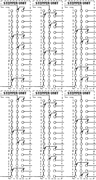
    Before I go forward I need to point out that the stepper unit animation I put on post #22 is not entirely correct. The arrows on the moving connecting wires should indicate the stepping direction but these are moving backwards:
    Stepping_unit_1.gifStepping_unit_1.gif
    The animation above is a resetable style stepper and the arrows are pointing downward. I should have made the arrows point upward because the animation steps upward.

    There are also steppers which step both ways such as a bonus unit. In that case the step-up direction will follow the arrows and the step down direction will be opposite the arrows. Make sense?

    So the proper forward direction of a generic continuous stepper unit will be as follows:
    Stepper3.gifStepper3.gif

    Here we are in our project. Next is the Coin unit and you'll see why knowing the direction of the stepper is important for you to understand more clearly:
    PPC10_(resized).pngPPC10_(resized).png

    I don't want to go all through the Coin unit circuit so here is a given sequence of events:

    A player will drop coins in the game to establish 4 credits then press the start button. The game will reset, deliver the ball to the shooter lane and be ready for player 1 to shoot the ball.

    Instead of shooting the ball, the player will push the start button again to establish a two player game. Then push the start button again for a 3 player game and once again for a 4 player game.

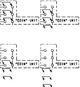
    When the player repeatedly presses the start button to add players, they are advancing the Coin Unit stepper. Each time the stepper unit advances another player is added.

    We know the schematic is drawn on player 1 of a 1 player game.
    I just mentioned the arrows on the schematic stepper indicate the direction of travel, so as the player adds more people to the game this is what the Coin unit is doing.

    Remember the schematic is drawn on player 1 and the animation steps to player 4 and repeats::
    CoinStepper1.gifCoinStepper1.gif
    That image is technically accurate but not really practical when diagnosing circuits.
    The animation below is more useful as we contemplate the sequence of events in the overall circuit (Note the animation below may not be in sync with the similar animation above).
    CoinStepper2.gifCoinStepper2.gif

    #73 7 years ago

    Moving past the coin unit we come across a Player Unit rotor disk and contacts along the bottom of the diagram.

    The path leaves the player unit and goes through a 3-5 ball adjustment and onto the "O" switch.
    The legend shows that "O" is part of the Ball Return relay.

    Without study, the Ball return relay goes on when the ball drops into the drain hole. The next device is the BX coil and the legend identifies it as the "Last Ball relay".

    We'll make a mental note in red about those devices:
    PPC10c_(resized).pngPPC10c_(resized).png

    Going down the line we come across MOTOR 2C.
    We can find it on the timing chart:
    Sequence_Chart_(resized).PNGSequence_Chart_(resized).PNG
    We notice where the switch changes state in the cycle and make a mental note on our diagram (Notice the timing chart I put under MOTOR 2C):
    PPC11_(resized).pngPPC11_(resized).png
    Next there are switches P2G, P3G and P4G. We've seen those same player unit cam switches before in post 54:
    Player_Cam_Docs_(resized).PNGPlayer_Cam_Docs_(resized).PNG
    Next in line is the "P" switch. The legend says it belongs to the "Add Player unit relay".
    Since switch "P" is open and current can't flow through it, let's take a look at how that switch works.

    I located the "P" coil on the schematic and here it is, the second coil from the top:
    P_(resized).PNGP_(resized).PNG
    This again looks way to complicated so I can follow the switches and lines to isolate the actual circuit. We discovered two MOTOR switches are involved so we need to consult the chart to find out how the circuit works. I've made a mental note and posted it on the schematic:
    P-Cln_(resized).PNGP-Cln_(resized).PNG
    The first thing I see is the coil name is "P" and there's a switch connected to it also labeled "P" which will likely be its locking circuit. Following its line I see that it connects to MOTOR 2B. According to the timing chart relay "P" will drop off at the very last of the cycle.

    If there's a lock then there must be a trigger to make it locked in the first place.
    I locate a switch connected between the P coil and the P switch and find the "I" switch. We looked at that before and already know it is on the Extra Ball relay. Further along we find a "THROUGH SWITCH".

    The through switch exists on the ball ramp between the drain hole and the shooter.
    The ball gets kicked out of the drain hole and rolls down a steel ramp, activates the Through switch and then drops in the lane where the player shoots the ball.

    Also note the "I" (Extra Ball) switch in series with the through switch.

    By that we can know that if the machine is in an extra ball condition then the Through Switch will not be able to turn on the "P" coil. Maybe that might be important to remember?

    We must consider the relay "P" will be locked on until MOTOR 2B releases it. The only way relay P can be released is if the score motor is turning.

    What can cause the score motor to turn?
    First thing to consider is the score motor circuit.
    There I find a switch "P" will turn on the motor causing the cams to turn:
    SM_(resized).PNGSM_(resized).PNG

    With all of that we know the "P" switch in our player up/ball counting circuit closes when a ball rolls under the lower pinball machine skirt on its way to the shooter lane (Unless the machine has Extra Ball activated) and the "P" switch will remain closed until the very end of the cycle then open again.

    Next is the BX relay which we recognize as the Last Ball relay, and finally MOTOR 1A. We can see MOTOR 1A is the impulse cam and we'll keep that in mind as I put it on the schematic.

    Like this:
    PPC13_(resized).pngPPC13_(resized).png

    We now have all the information needed to learn how the player unit pulses player up/ball in play.

    It is not normal to go through all these sub-circuits when trying to figure out a trouble. You can begin to recognize common patterns in circuits the more you work with them. Even from manufacturer to manufacturer, although they can name the same things differently.

    There are a lot of parts to this player pulsing circuit and I'd be overwhelmed to remember each and every one. I'd remember some things and make notes for the other things.

    I've said it is often easier to isolate individual circuits from the clutter by looking at what is on the left bus and what is related on the right bus. That's a general suggestion which mainly applies if no recognizable circuits exist. For example if a coil and switch are wired together and both have the same name it's usually part of a locking circuit so I'll often follow that path.

    The next post I make will be a method to process what makes this circuit pulse.
    I'll have to try to compile it in a clear presentation...Hopefully it will be understandable.

    #74 7 years ago

    As you know my aim at this presentation is to show a method to diagnose problems so you can figure it out yourself, while not so much as how something specific works. I'm finding it difficult to keep the two separated especially with this complicated circuit.

    But I'll try.
    You know we've been analyzing what the individual switches do and how they affect the operation in our player pulsing circuit. Now that we have all the information we need, it may help to take an inventory of everything involved. I'll begin from the right bus and move to the left:


    *A closed Extra Ball switch (I) that will open if an extra ball is queued.
    *An open First Ball switch (U)that will close and remain closed after the ball hits the first 10 or 100 point playfield switch.
    *A Coin Unit rotor/disk with arrows on all connections.
    *A Player Unit rotor/disk with contacts wired together on steps 8-11 and steps 16-19.
    *A 3/5 ball adjustment plug.
    *A Ball Return switch (O) that will close when the ball sits in the drain hole.
    *A Last Ball relay coil (BX)
    *An open Score motor 2C switch
    *Player unit cams P2G, P3G and P4G.
    *An open Add Player Unit relay switch (P) that will close as the ball runs under the lower skirt to the shooter and start the Score motor.
    *A closed switch on the Last Ball relay (BX).
    *An open Score motor 1A switch.
    *The Add Player unit solenoid

    My first consideration is how power can be routed to the solenoid coil.
    Current won't flow through open switches so those will be my first areas of consideration.

    The open switch "U" first ball relay switch is pretty simple. The ball hits a 10 or 100 point playfield item and my switch closes. So that's pretty much a given and I may consider that a closed switch.

    There's an open switch on the other side of the player unit rotor/disk. But it leads out of the path to the Player unit coil and onto the BX Last Ball relay instead so I'll disregard that section for now.

    Next is a row of 4 open switches: P2G, P3G, P4G and Score Motor 2C:
    4OpenSw_(resized).PNG4OpenSw_(resized).PNG
    At this point in time it is not clear how to make a circuit path through any of those. So I just make a mental note that it will need to be solved and move on. It may become clear later.

    I see an open "P" Add Player Unit switch and open Score motor 1A.

    Nothing here is really obvious and my biggest concern are this cluster of switches:
    4OpenSw_(resized).PNG4OpenSw_(resized).PNG

    Going through a process of elimination:
    *We know the three switches P2G, P3G and P4G rotate with the player unit. We also know the player unit won't be turning until its solenoid is pulsed so I can eliminate those from consideration for now.
    *Only the Score motor 2C switch remains so that must (somehow) become the path.

    We know the only way for Score Motor switch 2C to close is if the score motor is turning.
    How can we get it to turn?
    We can see in our inventory that the Add Player Unit relay switch (P) will start the score motor when the ball is on the way to the shooter lane. Additionally it will close the now open "P" switch.

    Great, now we know how to make a circuit path through those 4 clustered mystery switches (By running the score motor).

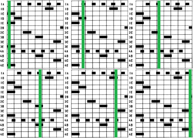
    That leaves the Motor 1A. Consulting the timing chart we see that it is an impulse cam that delivers 5 pulses per cycle.

    Doesn't it make sense the two score motors must be closed at the same time to deliver a pulse to the player unit? Technically they are wired in series so "this switch and that switch must be closed for the electricity to flow.

    I think there should be a point in time on the score motor when both Motor switches are closed together.

    I bet I can verify that hunch on the timing chart.
    We already know the player unit solenoid will end up needing 4 pulses so the two score motor switches should turn on toward the beginning of the cycle.

    The score motor operates like this on the chart, pausing at home position:
    Timing_chart.gifTiming_chart.gif
    Sure enough I find a position on the chart where switches 1A and 2C are both closed at the same time. Plus it is the first of 4 impulse cam switches which I also expected:
    Sequence_Chart_2_(resized).pngSequence_Chart_2_(resized).png

    I can start to assemble a logical sequence of events:
    1. The ball hits a 10 or 100 point playfield switch.
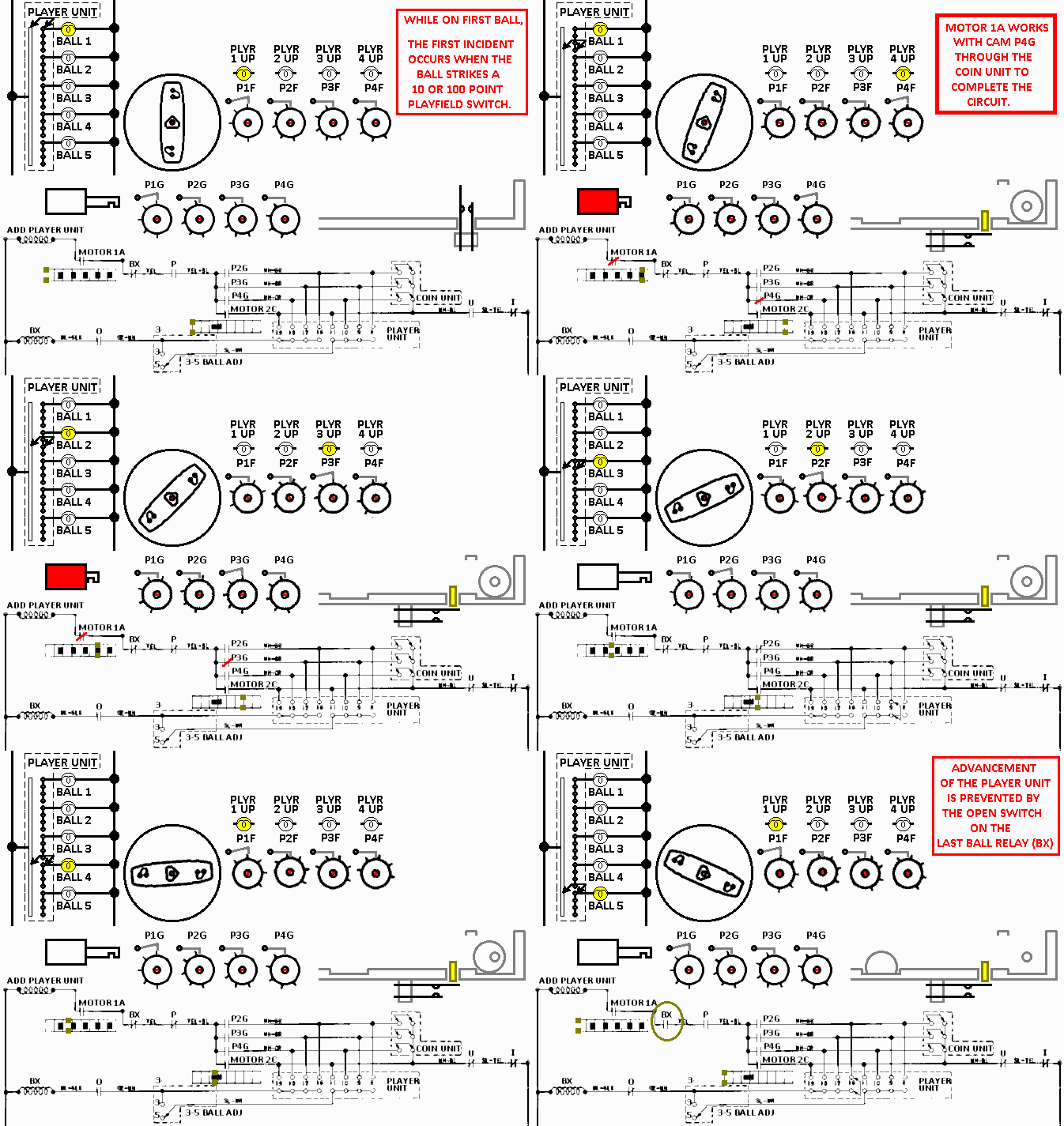
    2. The ball eventually drains, bonus's added and the ball is kicked out to the shooter. On its way to the shooter it rolls over the circuit for "P". The score motor runs, both score motor switches close and pulse the player unit solenoid.
    Like this. The orange block in the timing charts indicate the position:
    Web_Pulse_1_(resized).pngWeb_Pulse_1_(resized).png

    The player unit advances when the solenoid releases. When that happens then we know cam P2G will be closed.

    Now there is another path for current to flow through our mystery switches.
    So the cycle can continue and when the next impulse cam closes Motor 1A, another pulse will be delivered to the player unit:
    Web_Pulse_2_(resized).pngWeb_Pulse_2_(resized).png

    Again the Player unit solenoid releases from the impulse and the cams turn again, closing switch P3G, creating a different path:
    Web_Pulse_3_(resized).pngWeb_Pulse_3_(resized).png

    The process is repeated once more:
    Web_Pulse_4_(resized).pngWeb_Pulse_4_(resized).png
    When the solenoid releases the cams rotate back to player 1.

    We consider the ball is sitting in the shooting lane, the player can shoot the ball and play it. When it drops back in the drain the process can repeat. We might contemplate the function of some of the other switches. For example if an extra ball is in queue then it's switch on this circuit will be open and the player unit can't pulse.
    Effectively giving them an extra ball.

    Why would they put a switch in for the first ball relay?
    Have you ever shot the ball onto the playfield and it didn't hit any points but instead miss everything and go into the drain?
    If that happened in this game then the player unit couldn't advance and just deliver the ball back to the shooter.
    Slick!

    But something's got to happen to end this process after the last ball else the game won't end. A counting circuit isn't a counting circuit until it knows it reaches its end.

    See the Player unit rotor/disk along the bottom. The numbers indicate the stepper position beginning at zero. (Zero being its first position- Player 1 Ball 1). Looking closely at it the switch positions are pretty high, beginning on 8 to 11 steps and 16 to 19 steps.

    We also see the Ball Return (O) switch is in series with the Last Ball relay (BX).

    It isn't too far off to consider that when the stepper reaches high enough to get through the Player unit rotor/disk, that when the ball drops in the drain (Turning on the Ball return relay) that the Last Ball relay (BX) will come on.

    We already know a BX switch exists in series with the Player advance solenoid so when the relay goes on, that switch opens to prevent further counting.

    Below is an animation of the 1 player 5 ball game:
    Stepper_ckt_Super_8_colors.gifStepper_ckt_Super_8_colors.gif

    Here is the coin unit again as it would be for a 1, 2, 3 and 4 player game (no arrows are a 4 player game):
    CoinStepper2.gifCoinStepper2.gif
    *Can you see how it effects the number of steps applied to the player unit solenoid?

    Also take a look at the stepping arrow on the bottom Player unit rotor/disk. It will cycle through the proper switch positions.
    *Can you see how changing the 3-5 ball adjustment will effect when the game ends?
    *Can you see how changing the numbers of players in the coin unit effect the connections to the Last ball (BX) relay?

    #75 7 years ago

    Here's a couple noobe exercises.
    First, there is something wrong with all 3 switches here. What ever they do in their circuit it won't work right. Can you spot the defects?
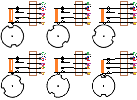
    Bad_Cam.gifBad_Cam.gif

    The relay problem below may be a bit more challenging to figure out. Here are some givens:

    *The relay pulls all the way in but it "hangs" half way out when power to the coil is cut. As a result only some of the switches make/break correctly...if they work at all. Or the contacts are intermittent.
    *There is no bind in the armature movement and the return spring is normal.
    *Although the switch blades on the animation look weird, yours look straight and normal.
    *The condition exists mostly on small relays with a lot of switches with little normal armature travel to begin with.

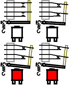
    Why won't the relay relax normally on the animation below? The one on the left is normal the one on the right is not:
    Bad_Rly.gifBad_Rly.gif

    But I want to wrap up the counter circuit. How does it actually change players?

    The player scores are indicated in the score reels so that might be a starting point to find on the schematic. Here are all 16 of them:
    Player_unit-score_reels_1_(resized).PNGPlayer_unit-score_reels_1_(resized).PNG
    It looks pretty complicated like all the others did.
    Again we need to see only the relevant circuits. If I look closely there's separate circuits that go through the "Z" relays. The legend says the Z relays are part of the reset circuits so we can ignore them.

    Also, we can see some familiar relays: The 10 point relay (N), 100 point relay (M). We were working with those relays before so we can consider them part of our circuit here:
    Player_unit-score_reels_2_(resized).PNGPlayer_unit-score_reels_2_(resized).PNG
    That graphic is pretty big so I'll post just the tens units but the others work the same:
    Player_unit-score_reels_3_(resized).PNGPlayer_unit-score_reels_3_(resized).PNG
    On the right we see the Hold (R) relay. That's an always-on relay so the state of it will be opposite drawn.

    Further along the line is the 10 point (N) relay. We can recognize that as part of the 10 point score reel end of stroke (EOS) circuit. We know that "N" switch will close when the pinball hits a 10 point playfield switch.

    Next are switches we should recognize by now: Player unit cam switches P1D, P2D, P3D and P4D.
    Notice how P1D is closed. That's because the game status is on the first player first ball. When the 10 point (N) switch closes, the circuit is completed to the Player 1 10 point score reel solenoid.

    If player 2 was up then the Player unit would be advanced. Switch P1D would open and P2D would close to route the pulses from the "N" switch to player 2.

    And so forth.

    We've spent a lot of time analyzing this player circuit.... from switching of lights to pulsing to switching players.
    Honestly I got about half way through and realized this is probably way too advanced for those just starting out, it's my hope folks were able to pick things up anyway.

    Ok back to the answers to the questions on the top of this post.
    The three cam switches:
    Bad_Cam.gifBad_Cam.gif
    *The top switch is broken. There are a couple hints that a switch -should- be there. The first hint is there's a contact rivet on the blade below and the broken switch has wires soldered to its connection tab.
    *The middle switch is adjusted so it never opens.
    *The bottom switch is adjusted so it never closes.

    Now the tricky relay question:
    Bad_Rly.gifBad_Rly.gif
    The lazy relay problem occurs when the switch blades which pass through the armature are adjusted incorrectly. They should be adjusted so no pressure is applied to the armature either up or down when the relay is relaxed. Those on the animation are pressing down on the relay causing it not to relax all the way. They fight against the spring and the armature rests somewhere in between.

    When someone comes across this a natural diagnosis is the return spring is old/sprung/worn out.
    Incorrect
    The switch blades need adjusting.

    With the player unit concluded I hope to delve into methods of trouble analysis and testing.
    But that's another day(s) or so. Thanks for helping to make this thread a success.

    #76 7 years ago

    Love this thread! Thank you so much!

    #77 7 years ago
    Quoted from SteveFury:

    Thanks for helping to make this thread a success.

    I think you get ALL the credit Steve. You have and are doing a great job here, thanks.

    #78 7 years ago

    Fantastic Thread and tutorial. Thank you Steve.

    I knew very little about EM pinballs but feel now that I could debug some easy failures. Thank you for going into this much details and teaching us how to read these very unorthodox schematics. In comparison, the first generation of Solid State pinballs is a piece of cake.

    I wish I could print your tutorial Steve. How about providing a PDF for your readers?

    Yves

    #79 7 years ago

    Yes thank you so much for sharing your knowlage and taking the time to go into such clear and detailed explanation and animations!

    It would be awesome if you document this in a pdf.

    Thanks Steve!

    #80 7 years ago

    If you all want to print it (you lose the cool animations, though!) then I might suggest that you click the little person silhouette (the head-and-shoulders one) beside a SteveFury post, which will filter only to Steve's posts in this thread.

    #81 7 years ago

    I registered in pinside just to say thank you for this guide, thanks you Steve.
    The animations and the pace is great.
    Don't be afraid to expand it to the maximum complexity.
    I always was tempted to study that EMs circuits, seems basic enough to try, buy complex in his core.

    Do you know this?
    http://markgibson.zenfolio.com/.../fun-with-pinball-small-boards

    Great Mark Gibson project to see this evil machines working.

    #82 7 years ago

    Thanks for the comments and compliments especially the newbees.

    I plan to go over some troubleshooting methods but please let me say this first:

    You should identify any/all the line voltage devices in your machine before you work.
    Some motors and bank reset solenoids operate on 120/240 volts and they are often switched through the score motor and relay(s). There may be a potential for lethal shock on a score motor switch(s) and other devices.

    Find and remember all the line voltage devices and danger points before you begin working on your game. They should be listed on the plug side of the transformer. Like here:
    Shock_(resized).PNGShock_(resized).PNG
    We can see that a shock hazard exists on the main 10A fuse, on-off switch, the Game Over relay, the transformer and the "Swinging Target" motor.
    You should also consider other non-obvious things. The Swinging Target motor on this game is located on the playfield. We know the playfield is connected via Jones plug so two pins on a playfield plug will be "Hot".

    Not to be scary but to be aware.

    I should also say that you should work on your pinball while it is unplugged if possible. Sometimes it is necessary to have it on but follow the "One hand" rule. That's to keep one hand behind your back when you need to touch something.
    Be safe!

    With that said, when troubleshooting....

    Be investigative and observant in your initial diagnosis and save time. You won't usually need to pull out the schematic when something stops working (Except for the disclaimer above). More often than not you can use a process of elimination coupled with investigative observation to fix a problem.

    If a machine has multiple failures it is best to stick with solving one problem at a time.
    Was it working before you did something? You can sometimes backtrack to find the cause. Did a playfield a switch get bent during cleaning/waxing? Perhaps a rubber rebound ring has lost some of its flexibility and doesn't operate the switch as it used to. Maybe the switch just needs cleaning.

    Suppose a 100 point playfield switch stops working.
    Do all the other 100 point switches work or is it just one switch?

    A 50 point roll-over lane will almost always have a 50 point relay.
    When a failure occurs, the first concern would be the roll-over switch because it's the easiest and fastest to check. If no trouble is found then visually check the 50 point relay for proper manual operation. Check that each switch makes and breaks properly and the armature doesn't bind.

    My point here is simply that most problems can be solved by looking around rather than in-depth troubleshooting.

    If your pinball machine doesn't start properly...maybe you can get it to serve up a ball by pressing this relay or that relay with your finger. You should fix the reset problem first.
    Consider this analogy:

    You'd fix a computer boot problem before worrying if the printer is out of paper.

    If your car doesn't start you wouldn't worry about low tire pressure.

    It's the same thing. There's lots of good people here who are willing to help.

    Sometimes you may need to do some deep troubleshooting and I plan to post some tips over the next few days.

    #83 7 years ago

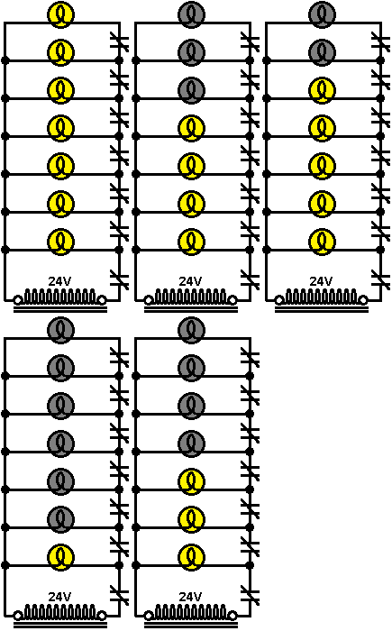
    You can often find a defective switch by observing what other devices are doing (or not doing) on the same circuit.

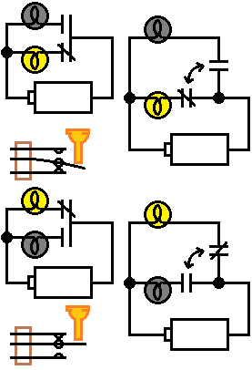
    See the animation below.
    You are trying to figure out the problem with the very top light.
    Current must pass through all seven switches to reach the top light.
    You can spend all the time (Waste the time) required to test all seven switches but that is not necessary.
    Below are 5 slides and 4 of them have a defective switch.
    Can you tell the bad one on each slide?
    You can often quickly find the bad switch by observing what other associated devices are doing:
    Lites_1.gifLites_1.gif

    Here is a scenario.
    You have a pinball with an eject hole feature that doesn't work.
    Observation shows the ball dropping into the hole, the points are tallied and the ball remains stuck in the hole with the machine tallying away until the power is turned off.
    You do some preliminary checks. You look over the eject hole relay switches etc. All appears good so you look at the schematic.

    Finding the eject coil itself would be a good way to start so you can find out what turns it on.
    You locate the coil below (Top, right) and the circuit looks fairly simple. It goes through 3 switches before reaching the coil (Red line):
    Coils_1_(resized).pngCoils_1_(resized).png

    You will have to check all 3 switches, right? Wrong!

    If you notice the shooter coil just below the eject coil, that it follows through two switches shared by the eject coil (Motor cam switches 5-B and 4-C). You do more investigative observation and drop a ball in the shooter lane and watch it operate normally.
    The fact the shooter coil worked rules out problems with the motor cam switches. That leaves only the Eject relay switch.
    So you clean that switch and it works.

    Sometimes you may be able to go further into the circuit (Green line).
    If we make a comparison with the animation to the game schematic, the eject coil would be the top lite, the shooter coil the second lite and the shooter relay the third lite.

    #84 7 years ago

    When you use a schematic as it relates to your game, you must keep in mind that a schematic is not a wiring diagram. The image below shows a simple wiring diagram and its schematic counterpart:
    Wiring_diagram_(resized).pngWiring_diagram_(resized).png
    You can see quite a difference between the two.
    The wiring diagram shows some devices such as Jones plugs that don't appear in the schematic. The wiring diagram have what looks like mystery wires that are confusing. Wiring colors are sometimes different than posted on the schematic. Old/dirty/faded wire colors make it impossible to follow.

    So how to understand that mess?

    Notice the red letters in the schematic below:
    SchLites1_(resized).PNGSchLites1_(resized).PNG
    Consider all those "a" connections.
    On your game, all those a's are connected in a method which was easiest and cheapest to manufacture. All the a's can be soldered together in many different ways but the key here is they are all soldered together. For example if the top lite on the schematic is located in the head by the credit unit and the bottom lite is on the coin entrance, the connection "a" will be found on both.

    The schematic shows what is connected to what... But does not show any physical wiring routes.

    In the factory, the schematic was designed first then the physical wire routing was worked out on the game. Therefore when we troubleshoot a game, it's the schematic we reference not the game.

    Wire colors are usually marked on the schematic but are more or less useless.
    All the "a" connections usually have the same wire colors. Same thing with all the "b" wires and so forth.

    Look at the "h" connection near the top. One end connects to the lite and one end to a switch.
    If you need to know the wire color on the "h" side of the switch all you need to do is look at the wire colors on the lite which "h" connects.

    #86 7 years ago

    We're going to work out a problem in a machine using the concept outlined in post #83.
    The idea is to isolate a problem by means of testing other associated circuitry.

    Our pinball machine is designed so that when the player gets the items "A" + "B" + "C" lites the special. The special is located in the outlanes, left and right. The special alternates between the left and right outlanes during the game.

    Problem
    The specials feature used to work but they no longer award a game. The red "SPECIAL" lites light but no game.

    We unplug the machine for an initial inspection.
    First we inspect the outlane switches. Then the credit unit. We find a set of relays labeled A,B and C. Those are probably in our circuit so we inspect those. The switches appear to be working properly and the armatures operate normally. We find a credit/extra ball jack and find it plugged into Credit.

    All those things looks good so we go a bit deeper.

    We turn on the machine and start a game.
    We operate the item "A" on the playfield and observe the relay "A" go on. We operate item "B" and relay "B" goes on. We repeat again for "C" and the "C" relay goes on.

    We then observe the Special lite go on one of the outlanes.
    We press the lit outlane switch and nothing happens. We score some points somewhere else and the other outlane lights. We press its red lit outlane switch and nothing happens.

    Hmm. So far we have determined both outlane specials are not working. We note that as it may be helpful later.

    Nothing is found to be a quick and easy fix so we look at the schematic.
    Where to begin?
    We know the specials award games so we can locate the credit step up solenoid. We also know the outlanes light for special so we find those too. Here is the snippet below. The credit step-up coil on the top right and the outlane switches on the bottom right:
    Special_1.PNGSpecial_1.PNG
    There's a lot of complicated muckety muck in there, but we are able to find the pathway from one bus to the other... To the credit step-up coil:
    Special_1b.PNGSpecial_1b.PNG
    I count seven switches and an adjustment jack in that circuit. Gosh it would take a lot of time to track all those switches down. What a big job!

    You don't have to check all those dang switches!

    Instead, we begin to reconsider some of the muckety-muck we disregarded before.
    Our goal is to find something else that will operate the credit unit S.U. coil which is closer to the coil itself. Here we find a very simple circuit through the 10 cent circuit:
    Special_1c-10c.PNGSpecial_1c-10c.PNG
    We simply drop a dime through the 10cent slot or easier yet reach in the machine and manually operate the 10cent relay armature with a finger tip.

    The 10cent relay locks on, 1 credit is added to the counter then the relay goes off.

    Excellent. We have just verified:
    (1) The Credit unit S.U. coil is good.
    (2) The Credit unit can mechanically add a credit
    (3) The Credit unit zero position switch is not the problem.
    (4) The circuit is good to that point.

    Can we find something further in on the circuit?
    The red arrow in the graphic below points to the high score circuit (I took it out to keep the graphic size manageable).
    We score a bunch of points and discover that it adds games with the high score.
    Special_1c-10c-HS_(resized).PNGSpecial_1c-10c-HS_(resized).PNG
    Wonderful! We can consider:
    (1) The Credit unit S.U. coil is good.
    (2) The Credit unit can mechanically add a credit
    (3) The Credit unit zero position switch is not the problem.
    (4) The adjustment jack is good.
    (5) The game over relay switches are good.
    (6) The circuit is good to that point.

    See how the number of potential problems have been dramatically reduced by a couple simple tests and observation.

    Can we eliminate anything else?
    Let's consider the outlane switches and the change relay.
    I will tell you the change relay changes state when a 100 point score is made (I don't want to go through that ckt).

    We can see both out-lane switches go to the change relay.
    If only one lane was defective then those would be the prime suspect. But it's unlikely that both outlanes and/or both Change relay switches would be bad so we can skip over those. We can return to those later if needed.

    That leaves only 3 relay switches left. the A,B and C relays.

    There isn't any other circuit we can test those with so we inspect those relays again. The schematic shows those are "Make" switches which are normally open so we inspect all the normally open switches on each of those relays again.

    If we find one out of adjustment and fix it then great.
    If the inspection looks good then we can clean all the "make" switches on each relay.
    If it works after cleaning then great.

    If it still does not work then we need to get down and dirty.

    #87 7 years ago

    Hi Steve
    great, "concept post-83" --- quite often "a new pin (broken down) - nothing happens when I press the 'Start Button' ". I then use "concept post-83" -> I look in the schema -> Does the pin has an Adj. Plug for 1st Coin Chute "1 Coin 1 Play 1 Coin 2 Plays". I adjust for "1Coin 1 Play" -> try the 1st Coin Chute -> the result give hints. Great, You explain "concept post-83". Greetings Rolf

    #88 7 years ago

    Thanks Rolf.
    Ok, all of our attempts to find the Special feature problem has failed.

    We will need a tester.
    Some people choose to use a meter. Me? I choose not to use a meter to measure voltages through EM pinball switches. Why? because the very small insignificant current required to move a digital meter (And to a degree a mechanical meter) does not represent the current draw of a coil. For example a dirty/pitted switch might pass 0.05 amp and show full voltage on a meter but it will not pass the couple amps required by a coil(s). A meter is used for checking coil condition / ohms but may be misleading for voltage checks through switches.

    Instead I've created a very simple test jig for those difficult problems.
    Most pinball coils operate with 24-30 volts. You can go to your auto store and pick out the cheapest package of two brake light bulbs and use them. They must have the same product/part number.

    Automotive bulbs are 12 volts so you will wire them in series together (12v + 12v = 24v). If they are not the same kind of bulb then one may draw more current than the other and one will burn out.

    I've wrapped the bases of the two bulbs together with a dot of solder on mine and added a 4 foot wire lead with a clip on the end, soldered to the center light bulb terminal as shown in the testing images below. I also tie-wrapped the wires on the bulb and wrapped the bases with electrical tape so it won't short or cause problems should it fall into the game.

    Back to testing:
    We know the circuit works past the A,B, and C relays. Inspections show nothing amiss.
    We are going to essentially replace the coil with inserting our temporary light bulb tester in its place. Nothing is unsoldered or soldered at this point.

    Looking at the image below we locate the left bus in our pinball game.
    The schematic shows it as a -BLACK- wire.

    Being the main bus, most if not all solenoids and coils will be soldered to this bus throughout the machine.

    We can clip one wire of our light testing jig to a black wire on any solenoid or coil in the game.

    Our entire point in testing will be to discover the place in our circuit where the current stops flowing. That will indicate the failure point.

    We can begin toward the bus on the left but for discussion sake let's start on the left:
    Special_1_lite_tst_a_(resized).pngSpecial_1_lite_tst_a_(resized).png
    Notice how testing point (1) connects onto the red "f ".
    If you read my post #84 then you know all points "f " will be wired one to another in the game. The actual wire routing in the game may appear as unexpected but all the "f's" will indeed connect together.

    I consider exotic wire colors that contain tracers, codes etc to be unreliable. With the age of these machines what was once yellow is now slate, dirt has turned white to gray etc.

    I want to first put my tester on the indicated test point (1) but the relay has gobs of wires soldered to it. How can I find the one I need?

    Process of elimination can help. We know the "A" relay switch is a "Make-Break" so we can ignore all the others. We can locate the other two relay switches on "f ". Those would be the 1,000 point and Game Over relays. Process of elimination also helps on those.

    We are looking for a wire that is common to all three relays. If, for example we find a black/white wire on the A relay, and also find a black/white wire on both the game over and 1,000 point relays on the type of switch we expect then that is the wire we seek. (Incidentally black/white is what's listed on the schematic but it may be different in the actual game).

    So we clip our tester onto the "f " terminal on the "A" relay.
    We start a game and hit A,B and C to lite the specials.
    We can see that when the ball runs through a lit special then current should flow at our tester point.
    We press to close the lit lane switch and...... the light does not light.

    **If** the light illuminated then I'd check all 3 "f " connections for a failure.

    The next testing point would be the next switch closest to the left bus, test point (2) on the "B" relay.
    We find the correct wire as before, perform the test again and our jig fails to light.

    Again we get the same result on the "C" relay switch on our test point (3).

    So then next testing point is connection "c" on the Change relay.
    We run the test again and our testing bulb lights up!
    Special_1_lite_tst_b_(resized).pngSpecial_1_lite_tst_b_(resized).png

    Looking at the schematic this may be a failure on the "C" relay switch. Right?
    We connect our tester on the "c" test point and perform the test on the "C" relay but get no light:
    Special_1_lite_tst_c_(resized).pngSpecial_1_lite_tst_c_(resized).png

    Ok wait a minute. What the heck?
    The schematic says connection "c" goes to two switches on the Change relay and the "C" relay. Something is amiss!

    Going back to the Change relay, we begin to tug on the solder connections and a black/white wire falls out. It happens to lead to the "C" relay.
    We solder it back onto the other black/white wire found on the same relay and problem is solved.

    Some notes:
    In the scenario above, if the loose wire was not found on the Change relay then it becomes more difficult to solve.
    It would likely come down to physically tracing the wire through the wiring bundles in the game and find the failure point (To find out why all "c" points don't connect together).
    In a game where this feature never worked you may find anything, perhaps a cut wire. But this game worked before so that's not likely.

    If you wanted to positively verify your suspected broken connection, you could temporarily clip a plain test wire onto a "c" connection on the Change relay and the other end of the test wire onto connection "c" on the "C" relay and the feature should work normally.

    In tracing a suspected wire you may find it passes through a plug and socket.

    Be aware that some/most schematics do not show inter-connecting plugs like Jones plugs.
    Those are also a point of failure due to age-corrosion.
    The wire color soldered to the male side of a Jones plug should be the same as its mate on the female side.

    But you have successfully (and proudly) fixed your own game.
    We close the machine up, grab a beer, put our feet up and watch some tube while surfing Pinside.

    #89 7 years ago

    Great stuff Steve! Hey be sure to do a post on those nasty delay circuits, ie cap, diode, resister. ive got a Flip-A-Card not scoring like it should...

    #90 7 years ago
    Quoted from SteveFury:

    Thanks Rolf.

    If you wanted to positively verify your suspected broken connection, you could temporarily clip a plain test wire onto a "c" connection on the Change relay and the other end of the test wire onto connection "c" on the "C" relay and the feature should work normally.
    .

    Conversely I had an issue where a gameover relay was getting tripped when a certain feature was getting made... went to the extreme of disconnecting the wire at the score motor (the first switch closest to GO relay). Still did GO when the feature was hit. Closely inspecting the harness coming off the controll bank (where the GO relay was mounted) I found a needle like wire sticking up from a solder lug and it was pearcing the cloth sheath of a conductor of the harness, you guessed it the game over lead. A little snip and some insulting paper on the harness and we were all good!

    But yea a long aligator jumper is one tool in my tool bag. How else are you going to verify all the match bulbs? (ok I could work the AS stepper by hand)

    Ken

    #91 7 years ago

    Thanks Steve, I wish I lived closer to you to learn this lost art of EM repair.

    #92 7 years ago
    Quoted from SuperPinball:

    Thanks Steve, I wish I lived closer to you to learn this lost art of EM repair.

    Hell, I just wish I was closer to Steve so I could drink his beer and play pinball with him, I need a break from all my restorations.

    Great stuff on all the repair info for folks too Steve!

    Ken

    1 month later
    #93 7 years ago

    Great stuff Steve, not been here for a bit, but made a point to read your last post, Love your “Some Notes” bit.

    3 weeks later
    1 month later
    #95 7 years ago

    Steve,
    From your quote,
    "Thanks for the input.
    Here's a bit about the EM power supply, the transformer.
    The job of the transformer is to both isolate the rest of the circuitry from line voltage of either 120v or 240volts and to provide a safe working environment of approximately 24 or 30 volts for coils and (some) motors, and about 6 volts for lights."

    Now I am working on a Gottlieb EM machine, and I have a question regarding transformer output voltages.
    The following is what I am reading at the transformer. I am using commercial ground.
    The upper lugs are "High" = 68v, "Normal" = 66v, "Start" = 37v, "6" = 37v, "5" = 35v, "0" = 31v.
    The lower "Normal" = 0v which has one side of the line cord attached as well as 2 white conductors, and "5" = 120v which has 1 red conductor.
    Now I am concerned that I don't see an output of 6 volts for the light circuit. Am I missing something here?

    #96 7 years ago
    Quoted from Playdium:

    Steve,
    From your quote,
    "Thanks for the input.
    Here's a bit about the EM power supply, the transformer.
    The job of the transformer is to both isolate the rest of the circuitry from line voltage of either 120v or 240volts and to provide a safe working environment of approximately 24 or 30 volts for coils and (some) motors, and about 6 volts for lights."
    Now I am working on a Gottlieb EM machine, and I have a question regarding transformer output voltages.
    The following is what I am reading at the transformer. I am using commercial ground.
    The upper lugs are "High" = 68v, "Normal" = 66v, "Start" = 37v, "6" = 37v, "5" = 35v, "0" = 31v.
    The lower "Normal" = 0v which has one side of the line cord attached as well as 2 white conductors, and "5" = 120v which has 1 red conductor.
    Now I am concerned that I don't see an output of 6 volts for the light circuit. Am I missing something here?

    Measure the AC voltages directly across the transformer taps not with respect to ground.

    #97 7 years ago

    Hi SteveFury +
    after "basics" You write about GOTTLIEB - I allow myself to mention this - a nice picture of the Gottlieb Player-Unit: http://webpages.charter.net/chibler/Pinball/Images/CamPositions-4Player.jpg
    and here some Start-Up Sequences: http://user.xmission.com/~daina/tips/pub/emTips.html , greetings Rolf

    #98 7 years ago

    Steve, thanks for the description of your double bulb testing rig.
    This is a great thread, many thanks for your efforts. Over time through research and hands on I'm slowly figuring things out but it's no replacement for having a voice of experience giving a simple explanation of something that seems so complicated to those like myself.
    I've got a gottlieb Top Score that will!not! kick! out! the! ball!!!.argggh! The 'O' relay never seems to get the pulse to operate the kicker coil. Its making me crazy because it did work, and then wouldn't, then did, now not at all. I'll build me a testing rig and try again.
    willbeEM

    2 weeks later
    #99 7 years ago
    Quoted from willbeEM:

    Steve, thanks for the description of your double bulb testing rig.
    This is a great thread, many thanks for your efforts. Over time through research and hands on I'm slowly figuring things out but it's no replacement for having a voice of experience giving a simple explanation of something that seems so complicated to those like myself.
    I've got a gottlieb Top Score that will!not! kick! out! the! ball!!!.argggh! The 'O' relay never seems to get the pulse to operate the kicker coil. Its making me crazy because it did work, and then wouldn't, then did, now not at all. I'll build me a testing rig and try again.
    willbeEM

    I bought a Top Score last year for $100.

    Sad, sad shape as it was in a hay barn with the glass off, but it actually powered up.

    It will be a project and a half, but I know I'll be referring to this thread when resto time comes.

    #100 7 years ago

    Steve, here's a pic appropriate to this thread. This contact was the score motor continuation lead, ie keep the motor spinning between the 120 degree stop points.

    After a couple of spins of the score motor the contact would heat up and get electrical isolated. I could hold the pad with a pair of pliers and spin the finger, very loose.

    So yes a little toasty. Sometimes hard to find because these issues can be intermittent, you clean the contact, it work for a game or two but then return...

    20161106_105952_resized (resized).jpg20161106_105952_resized (resized).jpg

    There are 132 posts in this topic. You are on page 2 of 3.

    Reply

    Wanna join the discussion? Please sign in to reply to this topic.

    Hey there! Welcome to Pinside!

    Donate to Pinside

    Great to see you're enjoying Pinside! Did you know Pinside is able to run without any 3rd-party banners or ads, thanks to the support from our visitors? Please consider a donation to Pinside and get anext to your username to show for it! Or better yet, subscribe to Pinside+!


    This page was printed from https://pinside.com/pinball/forum/topic/em-pinball-circuits-basics-to-not-so-basic/page/2 and we tried optimising it for printing. Some page elements may have been deliberately hidden.

    Scan the QR code on the left to jump to the URL this document was printed from.