(Topic ID: 159104)

EM Pinball Circuits-Basics to not-so-basic

By SteveFury

7 years ago


Topic Heartbeat

Topic Stats

  • 132 posts
  • 50 Pinsiders participating
  • Latest reply 2 years ago by RetroDad65
  • Topic is favorited by 329 Pinsiders
  • Topic is sticky in its sub-forum

You

Linked Games

No games have been linked to this topic.

    Topic Gallery

    View topic image gallery

    0Fast-Draw-Work-23 (resized).jpg
    0Fast-Draw-Work-22 (resized).jpg
    0Shangri-La-Work-33.jpg
    schematic (resized).jpg
    Schematic scan 2 (resized).jpg
    Schematic scan 1 (resized).jpg
    Jack Layout.pdf (PDF preview)
    cam timing.pdf (PDF preview)
    Lug_ID.png
    Flipper_Strength_Range.png
    Flipper_Ckt.gif
    Flux_Lines.gif
    20161106_105952_resized (resized).jpg
    Special_1_lite_tst_c_(resized).png
    Special_1_lite_tst_b_(resized).png
    Special_1_lite_tst_a_(resized).png
    There are 132 posts in this topic. You are on page 1 of 3.
    114
    #1 7 years ago

    I'm making this thread mainly for those who had bought (or will buy) that used pinball machine and doesn't understand a thing about circuits, or doesn't understand it enough to get it working again.
    It's -not- about how to rebuild a stepper or other sub-units, and please open a new thread if you have questions about fixing a specific machine.

    Depending on interest I plan to go from Romper-Room basics and build upon the concepts and apply them to practical repair by reading and understanding pinball schematics. A click on the "thumbs up" link on the top of the posts will say a lot.

    I had began the concepts here in this thread: https://pinside.com/pinball/forum/topic/help-with-startup/page/2 and opened this thread series by a member's request. Please feel free to ask concept questions... or to provide input if you wish.

    With that said:
    The very basics:

    See the image below.
    Ckt_Basics_1__(resized).pngCkt_Basics_1__(resized).png
    Example A only consists of a light bulb and battery. There are no connections so the bulb is dark.
    Example B shows only one connection to the bulb. There is no return path for the electricity to flow so the bulb is still dark.
    Example C adds the second half of the circuit. The bulb lights because there is a supply path (Red) -and- a return (Blue) path.

    Every circuit needs a supply and return path for current to flow.

    Adding a switch:
    A switch can be added to make or break either the supply or return path. There are different types of switches. Below are the two most basic types. All pinball switches build upon these two concepts:
    Ckt_Basics_2_(resized).pngCkt_Basics_2_(resized).png
    A shows a basic "make" switch. If you press down the orange button it will mash the switch blades together and provide a circuit to light the bulb. Release the button and the blades separate causing the bulb to go out again.
    B shows a "Break" switch. This time the light is already lit and pressing the orange button down cause the blades to separate, extinguishing the bulb. Release the button and the blades touch again turning the light back on.

    Note that in most electronic circles these would be called normally open and normally closed switches. But in the pinball world they are referred to Make and Break.

    Also note the light can be a coil or motor, depending on what the circuit does in the game.

    #2 7 years ago

    Here are some switches along with their schematic symbols:
    Basic schematic switch symbolsBasic schematic switch symbols
    A "Make Break" switch, pressing the button "Makes" one side of the connection and "Breaks" the other.
    A "Shorted" switch (As I call it) all 3 blades short together when the button is pushed.

    Switches can be stacked and actuated in so many diverse configurations as you find them in the machine but they almost always follow those basic types.

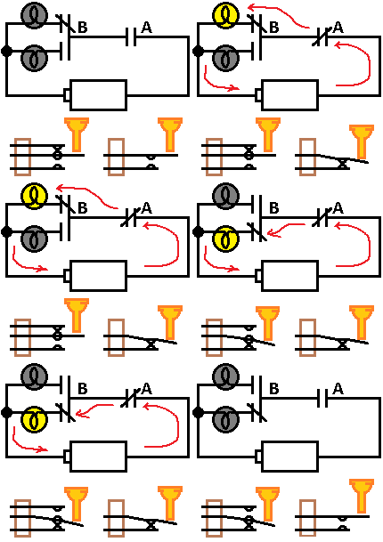
    The example below shows a simple make-break circuit. Please understand its concept:
    Make-Break circuitMake-Break circuit
    Changing the state of switch A will illuminate the top bulb. Releasing it will extinguish it.
    Changing the state of both switches A and B will make the bottom bulb light.
    Below is an animation activating the switches at random and the association in the schematic. Red arrows are the circuit path:
    Make-Break AnimationMake-Break Animation

    #3 7 years ago

    ALL of the circuits in a pinball machine only fall into two different types. Series and parallel circuits. Thankfully understanding them isn't too difficult.

    Take a look at the series circuit below:
    Series CircuitSeries Circuit
    You can observe the light will not illuminate unless switches A and B and C and D and E are all closed at the same time.
    When I am studying a schematic I think of switches in series as "and" switches.
    For example, I will recognize a series circuit and think "This switch, -and- that switch -and- that other switch need to close" in order for the device to operate. The device being a light, coil or motor.

    Now consider the two parallel circuits below:
    Parallel circuitsParallel circuits
    Both left and right circuits are wired and work the same, they are only drawn differently.
    You can see that closing A or B or C will cause the light to illuminate. It is important to consider that when one of the switches in a parallel circuit is closed, it makes no difference if the other switches associated in that parallel circuit close.
    For example, while switch B is closed it makes no difference if switch A and/or switch C closes.
    I think of switches placed in parallel as "OR" switches.
    I will recognize a parallel circuit in a schematic and know "This switch or that switch or that switch" will turn on the device.

    Getting a bit more complicated, see the series-parallel circuit below:
    Series-Parallel cktSeries-Parallel ckt
    Series-Parallel circuits combine the two types in one circuit path.
    You can see that switches A and B.... and also C or D or E have to be closed for the lamp to illuminate.

    It is absolutely essential that you have a good grasp of the concept of series, parallel and series-parallel circuits in order to diagnose and fix your machine in a methodical, logical and timely manner.

    #4 7 years ago

    I think a basic primer on circuits and schematics is a great idea and can really help those new to the hobby. Are you planning in the more advanced sections to take some basic, common, pinball circuits and explain their operation? Or maybe trouble shooting techniques using schematics for the top ten problem areas for the various manufacturers? Good work!

    #5 7 years ago

    THANK YOU!!!!

    I've been reading tech threads like crazy so I'm starting to pick up this info, but it's super helpful to have it explained clearly in one location!

    #6 7 years ago

    HI aahgo.
    I plan to continue with the very basics and gradually progress into more in depth concepts.
    My overall goal is to make this simple enough so most people can understand it. Hopefully it will eventually lead to the understanding of how to read a pinball schematic. Every "modern" EM pin have operational sequences some examples are reset, bonus counts, ball returns etc. Hopefully they will be able to know those sequences by reading their schematic.

    For most people outside of the EM arcade circles, when they have a pin that doesn't work they see the rows of relays, wires and are automatically overwhelmed. I've posted a few things on YouTube but I was taking for granted that people already knew the basics.
    So here I am posting the basics and working up.

    #7 7 years ago

    Great stuff!

    I have done a ton of stuff on my woodrails but I still can't read schematics that well and my head hurt reading the above but it all made sense . Well nearly all of it - the make/break section with how the bottom bulb lights kind of went over my head a bit.

    #8 7 years ago
    Quoted from Shapeshifter:

    The make/break section with how the bottom bulb lights kind of went over my head a bit.

    Thanks for the valuable input. I've added an animation (up in post #2). Please let me know if that makes it more clear.

    #9 7 years ago

    The animation does show it clearly, but it moves a little fast to register all the info at first. You might want to either break the steps up into separate loops or slow down the loop just a tiny bit. We noobs have to study the image closely to make sure we aren't missing anything on it, lol.

    Otherwise, the way you are breaking down the info is very easy to follow. My dad has shown me a little bit about reading schematics, and he never mentioned the part about needing a return path for a circuit to activate. I'm going to go out on a limb here, and guess that I will need to remember that when I get into more complicated circuitry.

    #10 7 years ago

    That makes more sense now

    And guessing this means that on that diagram it is not possible for both lamps to light at the same time?

    #11 7 years ago
    Quoted from Shapeshifter:

    That makes more sense now
    And guessing this means that on that diagram it is not possible for both lamps to light at the same time?

    That is correct.

    10
    #12 7 years ago

    Thanks for the feedback.
    We know our games have coils of different types. When current flows through a coil, a magnetic field expands throughout the coil. The expanded magnetic field will magnetize an iron slug "core" of the coil and it will become a powerful magnet. If the core is hollow with a loose iron slug partially through it, the magnetic field will encompass the slug and pull it inside into the center of the coil.

    A coil with a fixed iron slug is usually just called a "coil" but a coil with a movable iron slug core is called a "Solenoid". They are the type used to work the flippers, for example.

    One really cool use of an electro magnet is that it can be used to activate other switches. We know those to be relays.

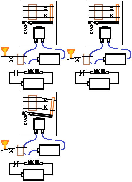
    Below is a basic common relay.
    Up until now I've used a light bulb as a load. This time I am using the relay coil instead of the light bulb. There is no circuit connected to the switches on the relay.
    Please observe these things:
    1. How the switches move with the armature.
    2. A spring returns the armature to rest when power is removed from the coil.
    3. There are two separate switches on this relay. Those are the switch types mentioned earlier, and they will also appear on various relays in your own game.
    4. How the schematic changes on the bottom:
    Relay1.gifRelay1.gif
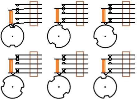
    Switches can be stacked into any configuration necessary to perform its function in the machine. It is often times when a single incident will need to operate several switches at a time. In that case the switches may be bridged together. Probably the most common use of bridging is on a Score Motor.
    We can consider the score motor and cams later, but for now just notice these things:
    1. How the switches are physically bridged (By a non-conductive nylon post)
    2. How a single incident (The follower dropping into the cam) makes all the switches change state at the same time:
    Cam_1.gifCam_1.gif

    Here's something else to mention about coils. When a magnet is moved across a coil then it generates electricity. The size of the coil, the power of the magnet and the speed of the magnet as it passes across the coil determines how much electricity is produced.

    As mentioned, a strong magnetic field exists when a coil turns on in your machine. That magnetic field collapses within the coil when power is removed and it can produce several thousand volts. Generally, medically speaking the tickle or jolt it produces isn't harmful. However it can be quite "Shocking" and alarming if it hits you. Of more concern is your reaction when it happens. Should you knock your soldering iron off the side and cause a burn, drop that wrench on your foot then it can be more than just a harmless tickle. Also note that if your skin is damp with salty sweat then it can be more of a jolt than otherwise.

    It is always best to work on your machine while it is unplugged. However there are times when you must have it on to troubleshoot. It is those instances I always suggest the "Keep one hand behind the back" trick. That way if you should get a tickle there is less chance it will go across your chest.

    The vast majority of most pins use a relatively safe voltage of 24 volts to operate coils and solenoids. However some games also use line voltage (120v or 240v) solenoids and motors so be sure what you are touching on a live game first.

    There is no reason to be paranoid or scared to work on your machine. Just be aware of what you are doing at all times.

    #13 7 years ago

    I love you, SteveFury.

    Topic favorited and followed closely. With my first EM restoration just coming up on the horizon, this will be a great help. THANKS!!!

    10
    #14 7 years ago

    Since we're looking at various switches, here are stepper units. I strongly recommend watching this video:


    It's not my video but is really good at describing the different types of steppers.
    I've whipped up a reset style stepper unit below.
    When you watch it notice these things:
    1. How he lights are connected to the rivets, how the rotor moves around to the next rivet as the step-up (SU) solenoid releases, turning on the next light.
    2. Below the rotor is a schematic representation.
    Notice how the arrow steps up and down as the rotor turns. Understanding the rotor switch is the arrowed schematic symbol is important to understanding schematics. That's the main reason I made the diagram.
    3. The operation of the coil schematic on the bottom left.
    4. Notice the supply and return paths for each circuit:
    Stepper AnimStepper Anim
    Below is the operation of a value-add stepper in a Gottlieb target pool. It supports 4 circuits making 15 steps. I am showing this mainly to display how such a thing is wired (Typical):
    Indicated_Value_Unit_Animation.gifIndicated_Value_Unit_Animation.gif

    Added over 8 years ago: The schematic animation I posted is not entirely correct. Please see post #72 for an explanation.

    #15 7 years ago

    Great stuff!

    I am reading this and beginning to understand a lot more. I have taken a stepper apart but never really understood how electrically it worked. Can see the physical stuff so good to understand the 'invisible'.

    I didn't really know that coils had magnets in them actually.

    And I am always fiddling around inside games with power on so this info is great as less chance of getting zapped!

    My mind went blank reading the basic common relay diagram. I understand it, I think - but the blue line that completes the circuit goes through what looks like a battery?? But em's don't have batteries. I must be missing something obvious here......

    #16 7 years ago

    Fantastic series. Really helps me understand more about the schematic I'm reading now. The animations really help in understanding the flow of everything. Really appreciate the animations, especially the amount of time you must spend on drawing these! thanks

    #17 7 years ago
    Quoted from Shapeshifter:

    I didn't really know that coils had magnets in them actually.
    Em's don't have batteries. I must be missing something obvious here......

    Hi Shapeshifter.
    The coils don't have magnets in them.
    If you take a single wire and put current through it then a magnetic field develops around it. If the single wire is arranged in a coil, then the magnetic field envelops the entire coil. When an iron slug exists within the core or center of the coil then the iron slug becomes a magnet because of the magnetic field expanded from the coil. When the current is cut off then the magnetic field collapses and the iron core is no longer magnetized.

    A transformer is used in our games to convert the 120 or 240 volt line voltage to a more safe 24v and 6v. I plan to look at transformers later but using the battery makes things simpler for now.

    #18 7 years ago

    Ok, moving onto some of the meat the the subject.
    We know that a relay is an electrically operated switch (Coil operated switch).

    A cool thing it can do, and is quite useful is to use one of the switches on the relay to lock itself on.
    It is also obviously important that once locked on, it needs the ability to be turned back off.

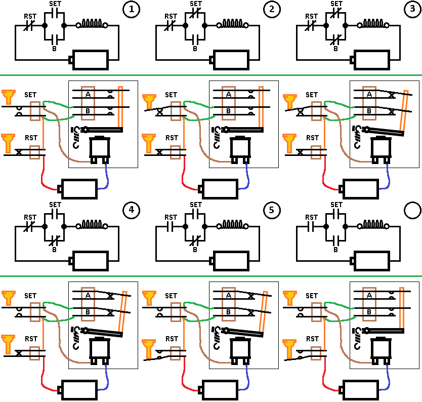
    We know a "Make" switch can be used to turn the relay coil on and off (See post #12). Let's call that switch a "SET" switch.
    We can wire the SET switch to another switch on the relay, so when the relay turns on then the circuit is electrically locked.

    The circuit will lock itself on until the power is removed. We can use a "Break" switch to accomplish the task. We can call that a reset or RST switch since it resets the circuit back to normal.

    See the image below. The circuit is idle or "normal. There is no path for the current to flow through the relay coil:
    RLY-2a_(resized).pngRLY-2a_(resized).png
    The two green wires arrange the two switches in parallel so they make an "or" circuit. If one switch or the other switch is closed then current will flow through the circuit. It is also becoming apparent how a schematic makes wiring schemes more apparent, as the maze of spaghetti wires increase.

    See below what happens first when the "SET" button is pushed:
    RLY-2b_(resized).pngRLY-2b_(resized).png
    Current can now pass through the RST button, through the SET button and energize the relay.
    RLY-2c_(resized).pngRLY-2c_(resized).png
    The relay goes on, closing the switch "B" on its armature.
    RLY-2d_(resized).pngRLY-2d_(resized).png
    The "SET" button is released. Now the relay has locked itself on by switch "B".
    The relay will remain locked in this state until its power is removed.
    See what happens when the reset (RST) button is pushed, killing power to the relay:
    RLY-2e_(resized).pngRLY-2e_(resized).png
    The relay armature drops off, opening its switch "B" and it returns to a normal state:
    RLY-2f_(resized).pngRLY-2f_(resized).png
    Folks seem to like animations. Here are the actions:
    1. Normal.
    2. Set button pushed.
    3. Relay locks on.
    4. Set button is released.
    5. RST button pushed.
    6. Relay drops back off:
    Rly-2.gifRly-2.gif

    You might ask "What good is this circuit"?
    This basic circuit is used all over your pinball machine. It's used in End Of Stroke (EOS) circuits we'll discuss later and more.
    You may have noticed for example, when the ball drops into the drain that relay turns on, maybe a bonus is tallied, the ball is ejected to the shooter then the relay drops off.
    The key steps to note here is the relay turning on.... probably caused by the ball dropping into the drain and activating the "SET" switch in this circuit. Then the other things happen and a cam on the score motor activates the "RST" button in the circuit.

    Or the ball drops into the hole and sits there while a score is rung then pops back out. There's a relay for that function that locks itself on, scores are made, the ball pops out then a cam on the score motor breaks the relay power causing it to drop back off.
    Just like in the circuit outlined above.

    #19 7 years ago

    Great job Steve, love the way you have included a schematically version and as built version, animated together. Looking forward to your next post.

    #20 7 years ago

    Thank you Chris.
    I was also wondering if this is moving too fast for folks to catch on.

    #21 7 years ago

    Looking good so far. I have done a lot of work going through the schematic of my first EM pinball machine, and I think it is all good so far. The lock-in circuit is a good one to lay out up front, just like you said it is used everywhere, and once you get the idea how it works, the little mini-circuits you are looking at start to make sense much more quickly. Just like when you figure out the score motor .

    I have been working on a possible thread that I think could supplement this one and might be helpful. I didn't so much want to cover the specific details of how the circuits work like you are doing. What I did was to go through the entire schematic, every bit of it, and figured out how every last piece worked. It took months, but I managed to get it all figured out. As of now, it is completely written down and I am working on the pics. This will include a list of every single switch in the machine, which includes where it is, which position it is on a relay, what wires are connected to it, where those wires go, and what the function is. It is turning out to be a massive project, but fun for me.

    #22 7 years ago

    Thank you xsvtoys.
    I plan to eventually move onto schematic's in a very generic manner after the basics have a good foundation. That's a reason I'm curious of how well this is being absorbed so far. I don't want to advance too quickly and loose an opportunity.

    #23 7 years ago

    Steve- i understood this stuff for the most part already but thisis really well done and I am enjoying reading it. Please keep up the good work. Others will have to chime in but I dont think this is moving to fast. You have presented the info very clearly. Great job

    #24 7 years ago
    Quoted from SteveFury:

    Thank you Chris.
    I was also wondering if this is moving too fast for folks to catch on.

    It's moving at a perfect pace. I haven't read a word of it yet. I've favorited it and skimmed the updates and will study it when my brain doesn't hurt from work. Keep up the great work with the posts, Steve!

    #25 7 years ago

    Thanks for the input.
    Here's a bit about the EM power supply, the transformer.
    The job of the transformer is to both isolate the rest of the circuitry from line voltage of either 120v or 240volts and to provide a safe working environment of approximately 24 or 30 volts for coils and (some) motors, and about 6 volts for lights.
    On a schematic, the transformer can appear near the top, bottom or one of the sides depending on the manufacturer. They're easy to spot and all work the same way. The vast majority will have a 120/240 input (Depending on your line voltage) and two output coils of 24 or 30volts for solenoids and 6volts for the lights.
    Below shows a comparison schematic of a transformer and my battery circuit to show its similarities. Notice the red arrows. They represent the main power bus.
    Transformer_1_(resized).pngTransformer_1_(resized).png
    On more modern EM pin schematics, the main power bus runs as parallel lines up/down or left/right depending on how the transformer is oriented on the schematic.
    Transformer_2_(resized).pngTransformer_2_(resized).png

    It is very important to know that electricity will *always* be trying to find a pathway between the two power busses.

    You can see the main solenoid/coil/motor power bus below. It's the blue parallel lines, and the light power bus (orange lines) on the left. Notice how all the coils and associated switches connect between the two blue main power bus:
    Schematic_(resized).pngSchematic_(resized).png
    I'll be incorporating the transformer in future schematic references. Space/size is a consideration when making these graphics so I'll only show the output coil and label it 24v, for a 24v supply:
    Transformer_3_(resized).pngTransformer_3_(resized).png

    I'll take a moment to make a note about fuses and their importance.
    I just mentioned that the electricity on one side of the power bus will always be trying to connect to the other side of the power bus. Light bulbs, coils, motors etc represent a specific load. The wire which the transformer is made of is designed to take those specific loads. Consider the schematic below:
    Transformer_4_(resized).jpgTransformer_4_(resized).jpg
    There is no useful work being done by the 24v supply, it only connects to itself. It is "Shorted". I say no useful work is being done but there is a lot of destructive work being done in the form of heat.
    The coil is trying to produce current, but the current is only flowing back to itself. The power being used will either cause the wires on your game... And/or the transformer to overheat with potential of fire. Most of the time it will cause the transformer to overheat and fail.
    That condition can be caused by many things: A wire comes loose and falls into an unlucky place, a bulb socket shorts, a light bulb breaks and the elements short...the list goes on.

    More times than not, the condition can be caused by shorting coils. Some coils, such as the CREM or coin lockout coil on the coin door, the HOLD coil on some machines etc. stay on whenever the machine is powered on. They are on all the time and eventually wear out.

    The coil wire gets warm which makes their lacquer coating dry out. Once the insulative coating breaks down then the coil begins to get hotter as the windings begin to short, drawing more and more current. The coil gets hotter which escalates the process. Eventually a serious short circuit is formed. The defective coil will burn in half and "open" if you're lucky, otherwise it's a slow death for the transformer unless protection is in place.

    Fuses protect the transformer and circuitry by becoming the weakest part of the circuit. Should a short occur, the fuse will blow and (hopefully) prevent a fire and protect your transformer. You can find them on your schematic in a similar place as this:
    Fuses_(resized).pngFuses_(resized).png
    You should always replace fuses with the same rating else you risk fire or a bad transformer. If you are unsure of the correct fuse rating it should always be stated on your schematic.

    You can go through a box of expensive fuses when troubleshooting a shorted circuit. To prevent this you can use a burned out fuse and solder a small circuit breaker of the correct rating across the fuse and use it temporarily until the problem is remedied and then install the proper rated fuse.
    Fuses_2_(resized).pngFuses_2_(resized).png

    #26 7 years ago

    One thing that drove me crazy when I first started trying to work on them is all the switches are overwhelming. Believe it or not (and I don't think I was alone in this) it took me quite a while to understand (nobody told me) that basically the switches have to change state. So for instance if you have a closed switch, when you pull in the actuator it should ALWAYS open. If it's open, it should ALWAYS close. So simple but so hard to understand, once I caught that the rest got much more simple.

    #27 7 years ago

    Hi Steve (+)
    You wrote "like feedback". To Your post-18 (Self-Hold-Circuitry) I made a JPG from (ipdb) schema "Cabaret".
    The player shakes the pin too much -> pendulum tilt-switch closes -> "encircled green" -> initial current flows -> coil on tilt-relay pulls in -> closes "encircled orange" its Self-Hold-Switch - > relay stays pulling until
    EITHER the "ball lost" enters Outhole -> -> pin steps to next player / next ball -> "encircled red" Switch on pulling Outhole-Relay opens (and the Tilt-Relay looses current)
    OR the Tilt happend on the very last ball played -> "encircled red" Game-Over-Relay pulls-in ... ()
    OR the frustrated player says - I START a new game -> "encircled red" the pulling Reset-Relay ... (). Greetings Rolf

    Cabaret-Tilt-Self-Hold-Circuitry_(resized).jpgCabaret-Tilt-Self-Hold-Circuitry_(resized).jpg

    #28 7 years ago

    Here's a few things about the score motor.
    The score motor is a timing and pulse generating device. It consists of a motor which rotates a set of cams, which in turn change the state of switches activated by followers riding- or striking the cams as they rotate.

    The score motor begins rotating the cams at a specific home position and stops the cams at the next available home position. The rotation from one home position to the very next home position is called a cycle.
    Most manufacturers divide cams to have two or three cycles per 360 degree rotation. Gottlieb for example divide their score motor cams in thirds. On those score motors, the cam will only rotate one third revolution to complete a full cycle. Williams divide theirs in half, so their cams rotate half a turn for a full cycle.

    How is the score motor used in games?
    Think about when the ball drains in the hole...suppose on ball one. If the game has a bonus feature, the bonus automatically counts down (Pulses are sent to the bonus unit), also the score reels add the results (More pulses to the reels) and when all that is completed the ball is kicked back to the shooter (Another pulse).
    If the pinball strikes a "500 points when Lit" how are 500 points added to the score?

    Much of that is also controlled by relays which are often times controlled by the score motor cams.

    I think a lot of confusion in reading schematics and learning how your machine does what it does falls in not knowing how the score motor handles the timing of events. I plan to build a simple 500 points feature, circuit by circuit for (hopefully) clearer understanding.

    I will arrange the physical representation of the circuit as plainly as possible but it will become more apparent how important schematic reading truly is in diagnosing problems because of the spaghetti effect.
    I'll begin with the home position cam/switch. The home position circuit ensures the score motor will always start and stop the cams at their proper rotational position.
    Note that my example score motor's full cycle is 360 degrees which is not normal as mentioned earlier.

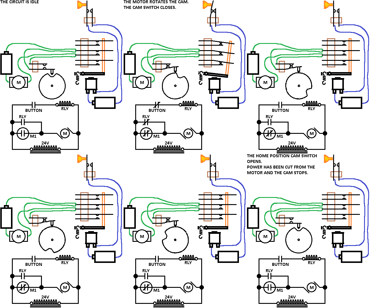
    The animation below is the first circuit in my 500 point feature, the home position circuit.
    The operation begins with the motor at rest.

    A button is pushed which starts the motor and the cam begins to rotate.
    A cam follower is lifted out of the slot and closes a switch.
    The button switch and the cam home position switch are connected in parallel so the button or the cam switch will complete the circuit to operate the motor.
    The button is released once the home position switch is closed.
    The motor drives the cam all the way around until the follower drops into the slot in the cam, opening the switch and stopping the motor:
    Score_Motor_Home_Position.gifScore_Motor_Home_Position.gif

    The main point to remember is that once the operation(s) are completed (Zeroing out scores, tallying bonus etc) is that the home position switch will always carry the cams to the next home position and stop the motor.

    #29 7 years ago

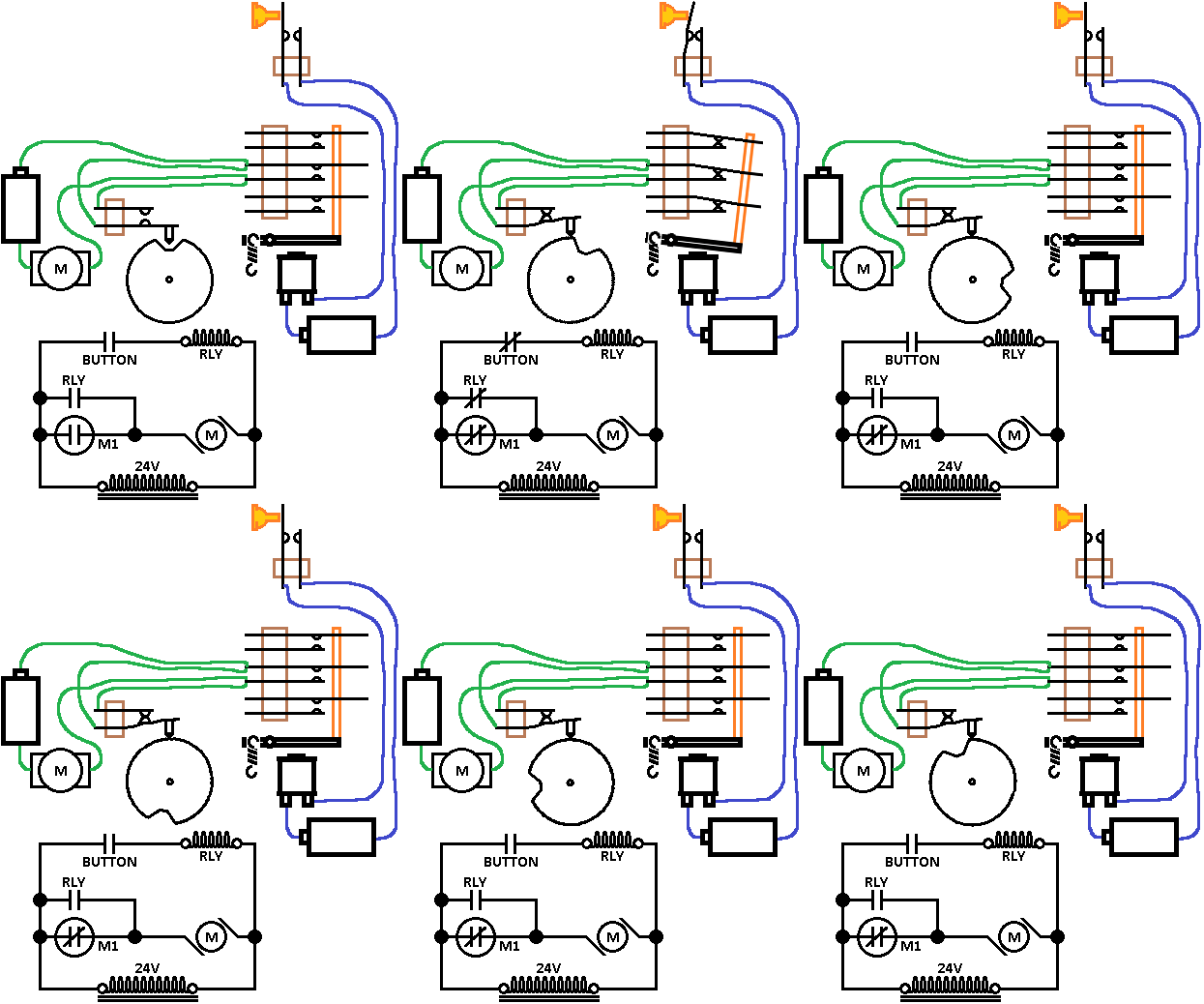
    I am going to add a relay to my scoring circuit.
    The push button turns on the relay, and the relay turns on the score motor.
    The button is released, dropping off the relay.
    The cam is carried back to home position by the home position cam switch.

    You may notice I've added a second power supply (Battery) to work the relay. I am adding batteries to cut down on the otherwise confusing wiring clutter.

    Below is a v-e-r-y slow animation followed by a full speed animation:
    Added_Relay_Steps.gifAdded_Relay_Steps.gif
    Added_RLY_Normal.gifAdded_RLY_Normal.gif

    I should also mention that a switch drawn inside of a circle indicates that it's a cam operated switch. The label of the switch indicates which cam it is. Here, for example M1 is Motor cam 1. More about additional cams will be later.

    #30 7 years ago

    Hi Steve-

    Great resource your producing!!!

    Your animation skills have been on a continual upward arc for a while now and your doing some really really good stuff! This is a very valuable resource for the community and it should be stickied??- maybe in the EM section, and required reading for anyone buying their first EM.

    A fun read- Its like watching a machine in action! Or at least pieces of it. Thanks for all the work your putting into this!

    #31 7 years ago
    Quoted from rufessor:

    Hi Steve-
    Great resource your producing!!!
    Your animation skills have been on a continual upward arc for a while now and your doing some really really good stuff! This is a very valuable resource for the community and it should be stickied??- maybe in the EM section, and required reading for anyone buying their first EM.
    A fun read- Its like watching a machine in action! Or at least pieces of it. Thanks for all the work your putting into this!

    It is a sticky, Em tech.

    #32 7 years ago

    Missed it!! Thanks

    #33 7 years ago

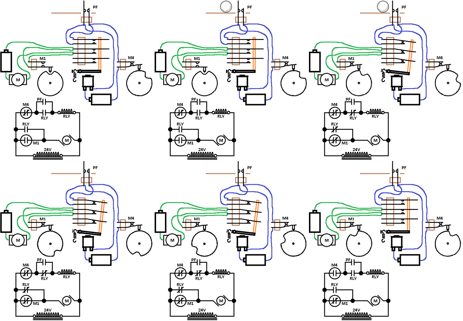
    Here is my next installment in the 500 point feature. Notice these things:
    *The button switch is replaced by a playfield (PF) switch.
    *The PF switch is wired to a switch on the relay.
    *A second cam is added.
    *A switch on the second cam is wired to the relay.

    You saw in the last post that the relay dropped off as soon as the button was released. It is more useful in these kinds of applications if the relay remains on for the duration of the cam rotation. In this circuit, the PF switch locks on the relay through its own switch (Remember the self-locking relay post#18). The relay remains locked until its power is interrupted by M4. Once the relay drops off then the cams are brought back to home position via the home position switch.

    Here's another v-e-r-y slow animation:
    2nd_cam_w_txt.gif2nd_cam_w_txt.gif
    Sometimes it makes more sense uninterrupted:
    2nd_cam.gif2nd_cam.gif

    #34 7 years ago

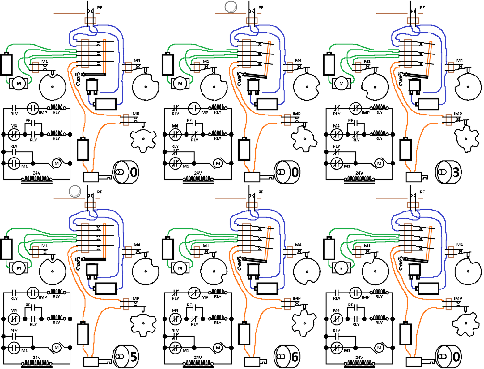
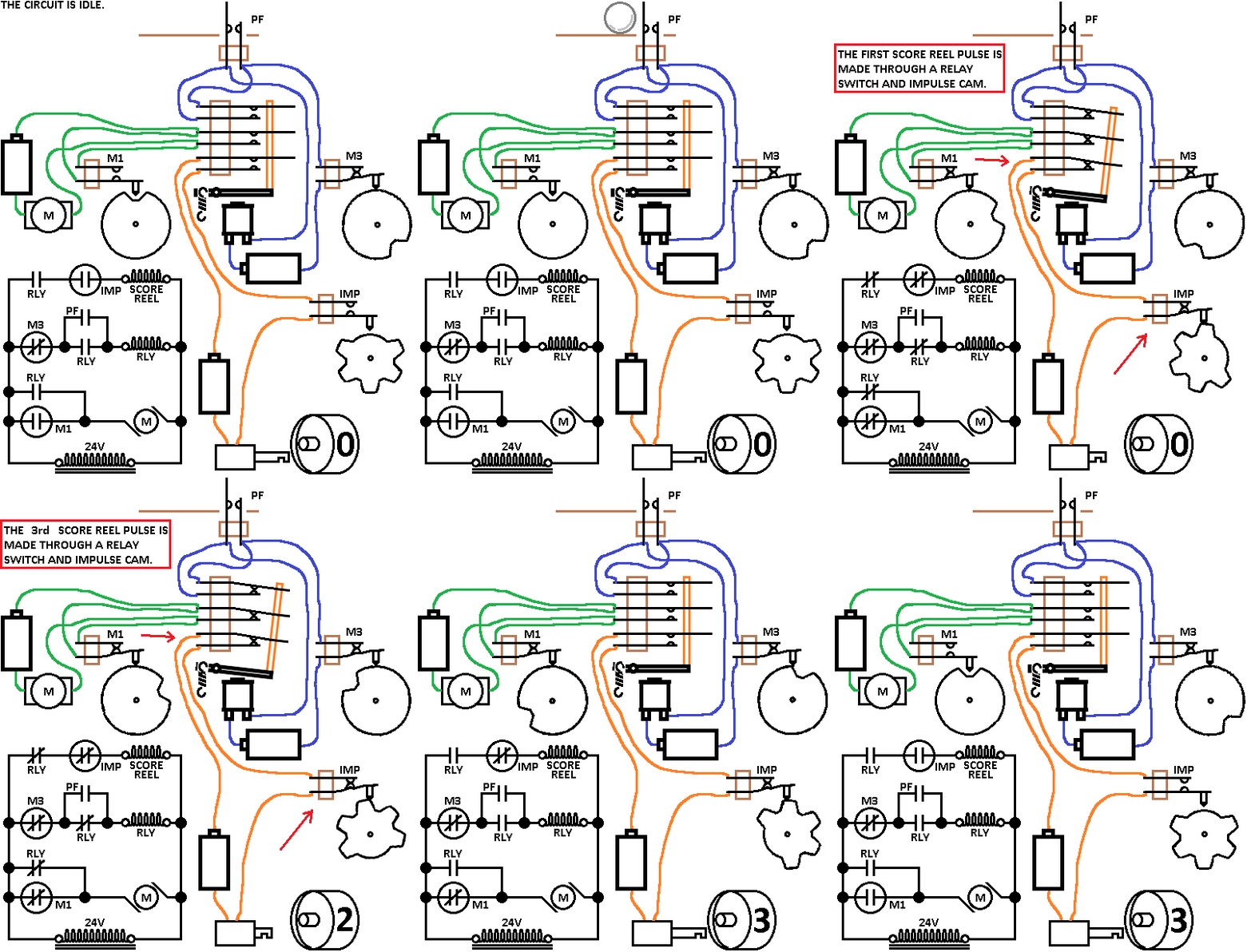
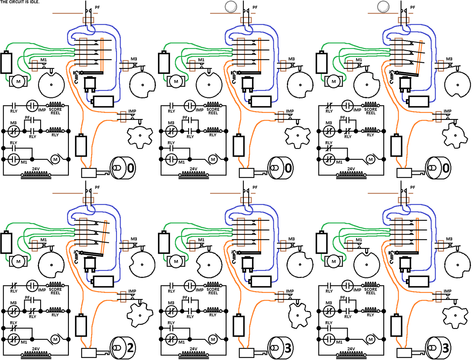
    I've finished my 500 point circuit.
    I added an impulse cam, an impulse cam switch and a score reel solenoid.

    The operation of the last circuit wired in orange should be pretty simple and straight forward.
    The relay pulls in which allows 5 pulses from the impulse cam to operate the score reel.

    We can explore how to locate these parts in a normal schematic, variations in the circuit to accomplish different tasks and how to figure out problems.

    If you've followed the building of individual circuits as I built this, you should be able to recognize each of them and understand how they play their part in its operation:
    500_Points.gif500_Points.gif
    I did notice a schematic error, the score reel is shown here in red:
    Correction_(resized).pngCorrection_(resized).png

    10
    #35 7 years ago

    We can see how several smaller circuits can be assembled to create a larger task.
    Does the above circuit make sense to folks: are you able to follow and understand it or is this -way- over your head?
    It would be useless to move on if it's completely confusing.
    Thanks for the input.

    #36 7 years ago

    Great pace for me. I get it and was well explained. Thanks for taking the time to do this. Much appreciated!!

    #37 7 years ago

    Pace is good for me

    #38 7 years ago

    I think everyone on pinside should be reading this thread. many here own games, but have no clue how they even work. It's like buying a car, and not knowing it needs oil, washer fluid, blinker fluid or what not. Everyone should have a basic understanding of all of this. Whether or not you own an EM or not. Because SS works the same way, just done electronically, but same principle. Your doing a fantastic job. Kudos to you.

    #39 7 years ago

    Thanks for the input.
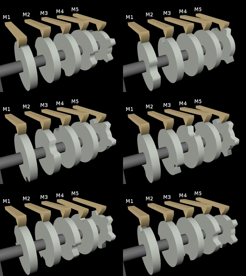
    You can see the timing of circuits are very important. The score motor can appear chaotic while its running but there's a method to the madness. Look at the score motor below. The closest cam, M1 is also the home position cam. We know this because the motor stops when the follower stops in the cam. On a real game, you could lift the follower with your fingertip and watch the motor cycle:
    Cam_Sequence_ani.gifCam_Sequence_ani.gif
    Notice how any switches actuated by M1 would change state first as the cams begin to rotate. Then followed by M2, M3 and M4 and always in that order. M5 simply produces 5 impulses and is often called the "impulse" cam.
    My animation is based on this style score motor:
    WSM.JPGWSM.JPG
    Another style score motor functions exactly the same except it is laid out differently:
    GSM.JPGGSM.JPG
    It may have less cams but the switches are arranged around the perimeter of the cams instead of in-line with them as in the previous score motor.

    #40 7 years ago

    The previous circuit was a 500 point circuit. The relay in that instance would be labeled the "500 POINT" relay.
    There is only a very minor change to do on that circuit to make it award 300 points.
    Take a look at the picture slide below. I'll call that relay a "300 POINT" relay.

    It looks exactly like the last circuit....right? It is wired the same but I have made a change. See if you can spot the change before looking at the next post:
    02_(resized).png02_(resized).png

    #41 7 years ago

    I'm hoping you caught the change from a 500 point circuit to a 300 point circuit.
    Reference the score motor animation I put on the last post (Post#39).

    Notice my 500 point circuit.
    The cam that drops the relay is labeled M4 for a reason. Based on my score motor animation, it is the last cam in the line to change state. Being the last to change state in the cycle, it allows all 5 impulse cam lobes to drive the score reel.
    M4_(resized).pngM4_(resized).png

    To make the 300 point circuit I moved the relay-dropping cam over to M3, which will cause the relay to drop out early.
    See the animation below:
    300_w_txt.gif300_w_txt.gif
    Below is a full-speed animation, it is difficult to see all that's going on just by looking!
    300_pt.gif300_pt.gif

    When reading a schematic, the ability to understand for example, that a score motor switch M3 changes state before M4 can be a key to understanding the circuit in question.

    Some manufacturers made that easier to see timing sequences than others. Some may require you to reference a timing chart. In this instance the black boxes indicate a change of state while looking left to right:
    Timing_(resized).jpgTiming_(resized).jpg

    #42 7 years ago

    Excellent stuff Steve. Great for the mech savy and not the so much tech savy. keep on keepin' on.

    #43 7 years ago

    Thank you for the input.
    Let's look at a real schematic and find an example of the circuits above.
    Looking at schematics can be a real confusing exercise but if we can narrow our search then it can be easier.
    If we are having problems with a 500 point circuit, for example then we won't initially be looking around the coin circuits.

    We know in most more modern EM pins the 500 point circuit will have (at least) these three smaller circuits for it to work:
    *A 500 point relay
    *A switch on the relay to operate the score motor (Drawn in green in my circuit)
    *A relay control circuit (Locks/unlocks the relay, drawn blue in my circuit)
    *A circuit to pulse the score reel (Drawn in orange)

    We'll first look at an example in a Gottlieb schematic. Gottlieb makes you reference their timing chart with letter assignments which make it a bit more difficult. Just perfect to begin with.
    Since we know the 500 point circuit will likely have a 500 point relay, let's see if it exists on the schematic. We do that by first looking at the relay list. There it is assigned as coil "D":
    RLY_List_(resized).PNGRLY_List_(resized).PNG
    Now we can expect to find a switch "D" in the score motor circuit.
    Notice all these score motor switches are wired in parallel so it's "This switch or that switch or that switch" will complete the circuit to turn on the score motor.
    So here we find switch "D":
    SO76_SM_500pt_(resized).pngSO76_SM_500pt_(resized).png

    Click any schematic for a clearer view.
    Keep in mind the power bus is the parallel lines on the left and right of the schematics. Also keep in mind that the flow will always be trying to seek a path from one bus to the other bus.

    It is important to understand that switch "D" is not a switch on the score motor. The relay list shows "D" to be the 500 point so switch "D" can be found on the relay itself. Gottlieb score motor switches are labeled for example MOTOR 1C which can be seen on the right of the row of switches. By previous study we can know that is the score motor's home position switch.

    We've verified a circuit for "D" exists on the score motor circuit. Great so far, it is going as expected.

    Next we can find coil "D" in the schematic. That will be our 500 point relay coil. Here it is at the top left:
    SO76_500pt_(resized).PNGSO76_500pt_(resized).PNG
    We will next expect to find a circuit to pull the relay in, also the self-locking relay switch and a score motor switch to release it (Drawn in blue on my previous circuits).
    Below are all those elements:
    SO76_500pt_rly_Cntrl_(resized).pngSO76_500pt_rly_Cntrl_(resized).png
    The red arrow indicates the pull-in circuit path (What's before that is irrelevant at this point).
    We recognize the hold-in switch (Red circle) because the relay coil is "D" and the switch is "D"
    We see a cam "MOTOR 2B" which is wired in a way (series) so when it opens it will kill power to the relay coil. If we want to verify the switch MOTOR 2B will indeed open at the end of the cycle then we consult the chart:
    Gott_SM&Chart_(resized).PNGGott_SM&Chart_(resized).PNG
    Sure enough, Motor 2B changes state on the very last step.

    So far we've found the (green) score motor circuit and the (Blue) relay control circuit. How about the (Orange) pulse circuit?
    First thing I am looking for is the score motor impulse cam. I have to look at the timing chart to know which one it is:
    Gott_SM&Chart_(resized).PNGGott_SM&Chart_(resized).PNG
    Always looking from left to right on the chart, there is only one cam that has five pulses per cycle. It is either Motor 1A or 4A.
    The 1 and 4 denote the score motor switch location (See the motor diagram above the chart) and "A" is the cam.
    Since the physical switch location around the score motor is irrelevant for us, we are looking on the schematic for the impulse cam which we now know is assigned "A".

    We can find a MOTOR 1A on the very bottom right corner. We know that's the impulse cam because we saw it on the chart.
    SO76_500pt_imp_(resized).pngSO76_500pt_imp_(resized).png
    Following the line, we find switch "D" that we know is on the 500 point relay. Perfect so far. Looking further down the line we can see it ends up on coil "M". Looking again on the relay assignment we find that coil "M" is the 100 point relay.

    Since the 100 point relay drives the 100 point score reel, we know we've found all 3 necessary circuits.

    My goal in this post was to show how this circuit is implemented in an actual schematic. It may be helpful for you to consider different failure points and the malfunctions they may cause.
    What failures will cause the score motor to run and run without ever scoring any points?
    What things will cause the circuit to cycle over and over again, racking up endless points?
    What may be wrong if instead of always scoring 500 points, that is sometimes scores less, sometimes no points at all?

    #44 7 years ago

    Thank you for making these !

    LTG : )

    #45 7 years ago

    You're very welcome.
    Let's look at a variation of my previous circuit.
    We know the difference between the 500 point and 300 point circuit outlined above is the timing when the relay drops out, according to which cam it is wired to.

    With that said, let's look at a simple variation of that circuit.
    The only modification I am making is to the relay coil control circuit so I've eliminated all the others, except in the schematic:
    300-500Adj_plug_(resized).png300-500Adj_plug_(resized).png
    You can see that I've added an adjustment plug so that either the Motor cam 3 or the Motor cam 4 switches can be selected for the circuit.
    That is a typical arrangement scheme for a "Liberal or Conservative" feature scoring adjustment or coin credit adjustments.

    Below is the schematic for a 1976 Williams game.
    Here are a couple of great example circuits we can go through.
    The game has a feature called "super advance" and it has an interior adjustment plug so it will advance the bonus unit either 3 (Conservative) or 5 (Liberal) steps.
    SU2_(resized).PNGSU2_(resized).PNG
    You can notice the graphic has an upper and lower part connected by a thin red dotted line. The bottom part is way, way down near the bottom of the long schematic. Instead of drawing a long line, they put an arrow with a reference. I've eliminated the middle part and drew the line for clarity.

    Focusing on the relay control (Turning on the relay and cutting power to it), find the Super Advance relay on the blue line below:
    SU2m_(resized).pngSU2m_(resized).png
    You can follow the green line toward it and see that a roll over button will turn it on.
    You can follow the blue line from the Super Advance relay and see it goes to a Super Advance Relay switch. We know that will be its locking switch, located on the Super Advance relay itself. We also know the other end of the switch will be connected to a cam which, after a certain time will kill power to the relay.
    Notice it goes through a jack similar to the one I drew in my diagram.
    The LIBERAL selection will direct it to go to cam 5 (5A) which is the last cam to open on the score motor. That will keep the Super Advance relay on long enough to allow all 5 pulses to the bonus unit.
    If the jack is set to CON(servative) then it will follow the red dotted connecting line, do a loopty - loop around to cams 3,4 and 5 until it reaches the other power bus. We know that cam 3 will open before any other in the list so the Super Advance relay will drop off when cam 3 opens.

    But there's a bit more in that schematic to view.
    See the red lines on the 50 and 5000 point relays near the bottom of the image.
    Do you notice any similarities to the circuits we've been looking at?
    We can call the green lines the "trigger" or "Set" circuit. For the 50 point relay, the ball hitting a stand up switch will turn on the relay. If you look down its red line you will see a 50pt relay switch. That switch is the lock switch on the relay.
    Same thing with the 5000 point relay, except the swinging target will trip or set it. It also has a 5000 point self-locking switch.

    The 50 point, 5000 point and Super Advance (Set to liberal) all share cam 5 to drop them back off. That fact may be a future troubleshooting tip.

    #46 7 years ago

    Using the upper half of the last image, notice there's a few coin circuits here:
    Coins_(resized).PNGCoins_(resized).PNG
    I'm going to be mean this time and not draw lines. See if you can follow without them.

    Let's look at the 10 cent circuit. Find the switch that activates it. Yes, that's it. It comes off the left power bus, through an anti-cheat switch to the 10cent coin switch (Don't get lost in the turns). Now you can identify its locking switch because it's named the same, the 10 cent relay switch, before it goes to the 10 cent adjustment jack.

    Just like before, the 10 cent coin switch will turn the relay on, and it is held on by the 10 cent relay switch.
    A cam opening the circuit will drop the relay back off. Which cam is selected determines the length of time the 10 cent relay remains on.

    Try to see how, if the jack is plugged into socket #2 then the 10 cent relay will drop off when cam 2-C opens. Plugging into jack #2 will allow the 10 cent relay to remain on until cam 2-C opens. Plugging into jack #3 will allow the 10 cent relay to remain on until cam 3-C opens.
    The credit unit or associated circuitry isn't shown here, but how long the relay remains on determines how many pulses are added to the credit unit.

    You can see the logic also follows the same for the 25 cent relay, and its many possible adjustment positions.

    So in review, we can see how this kind of circuit arrangement is used in so many places around our machines.
    If there's no objections I'll move onto something else.

    #47 7 years ago

    Rock on Steve!!! all good stuff!

    #48 7 years ago

    Sorry, I'm redesigning this post. I'll have it back up soon.

    #49 7 years ago

    Sorry, I'm redesigning this post. I'll have it back up soon.

    #50 7 years ago

    One inherent problem with EM's are delays caused in the mechanical units.
    For example, if the ball makes a glancing strike against a playfield switch, the pulse from the switch can be too short for the circuit to operate properly.

    Suppose the ball only lightly strikes the skirt of a pop bumper... hard enough for the plunger to move but not move completely down. Had the plunger been able to pull the ring all the way down to strike the ball, the game would have been more reactive for the player.
    Or if the ball strikes a single point switch but the resulting pulse is too short for the score reel to properly work.

    I bet many players felt cheated and beat up the machines. Perhaps that's a main reason why the End of Stroke switches were employed.

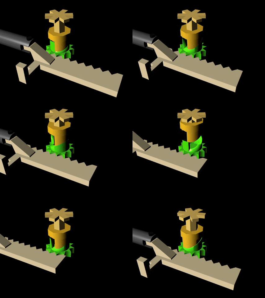
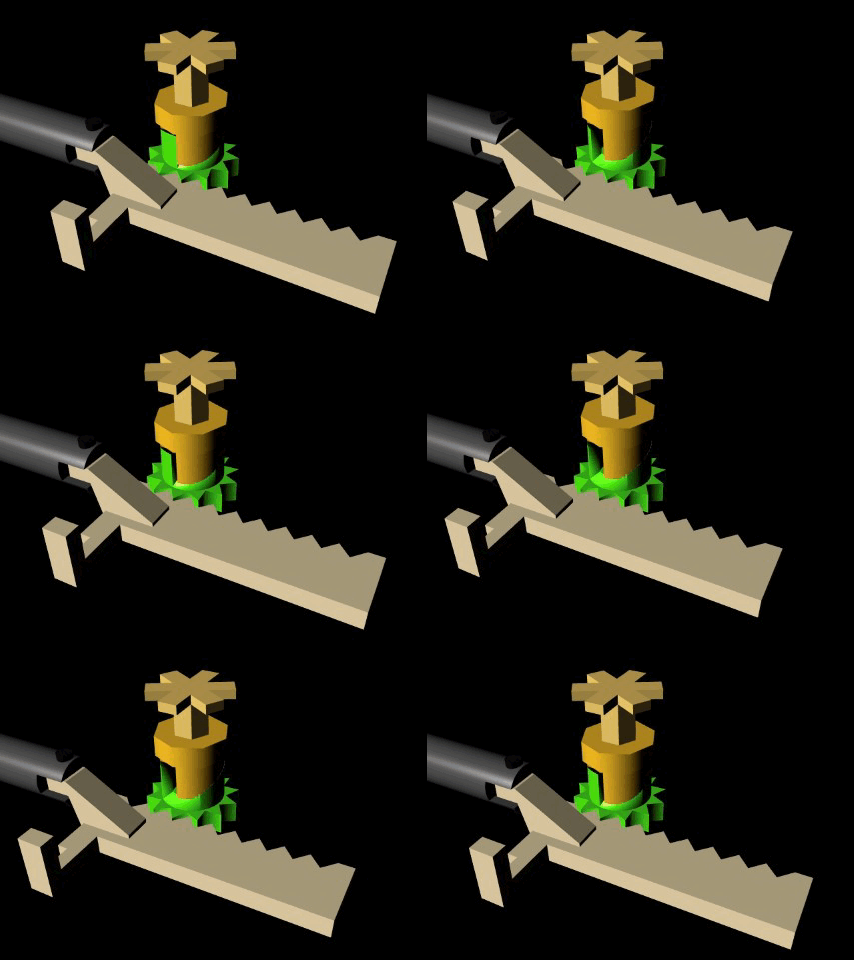
    Below is an animation of the mechanical portion of a score reel.
    The solenoid moves the flat gear, which turns a ratchet until the upper dog drops back down.
    A plunger return spring (not shown) rotates the reel.
    The star-shaped part on the top is supposed to represent the actual score reel:
    SC_FULL_STROKE2.gifSC_FULL_STROKE2.gif
    Below is what happens if the pulse is too short.
    The ratchet does not rotate far enough to clear the upper dog so the score reel does not turn:
    SC_HALF_STROKE2.gifSC_HALF_STROKE2.gif
    It is known that a relay armature has a faster mechanical reaction time than the iron slug of a solenoid. Especially when the slug is connected to additional mechanical devices.

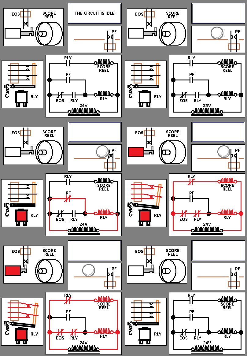
    To help reduce errors due to short electrical pulses, the playfield switch turns on a relay and the relay turns on the solenoid.
    The relay will remain ON however long it takes until the solenoid reaches full stroke. When the solenoid reaches full stroke an End of Stroke switch turns off the relay, and so the power is cut from the solenoid.

    Below is a normal speed animation of the process.
    I've eliminated the spaghetti wires to make it simpler:
    EOS_2.gifEOS_2.gif

    The relay in the above circuit would be called the "100 Point Relay" if it worked the 100 point score reel. If it worked the 10 point score reel then the relay would be called the "10 Point Relay".
    The relay would be located in the head of the machine.

    Below is a much slower explanation:
    EOS_2_TXT.gifEOS_2_TXT.gif
    The EOS switch is in a very high-stress application and is more prone to breakage than many other switches.
    If an EOS switch gets broken or otherwise is not able to close, the relay will not be able to lock itself on. However the solenoid will still operate because the PF switch can still momentarily operate the relay.

    Some people believe the EOS circuits aren't necessary in private in-home games as they are not likely to be vandalized by a disgruntled player.

    I can't completely disagree mainly because of a basic flaw in the circuit:

    If the EOS switch fails to open (out of adjustment, stuck mechanics etc) then the relay will remain stuck on "forever"...and also the solenoids the relay operates will remain on. Bells/chimes are also switched by most EOS relays so they will also be stuck ON. How many photos have you seen of games with burned out bell coils?

    The relays and solenoids these circuits operate are designed for short, intermittent duty and will overheat, smoke and burn in a matter of a few seconds.

    I gave my Williams Space Mission a complete inspection when I first got it home.
    I found a score reel solenoid melted down as in China Syndrome, It apparently caught fire and even burned away a portion of the fabric harness. You can see the harness repair at the score reel. It looked like it was an open flame to the relay above it:
    Harness_(resized).PNGHarness_(resized).PNG
    I keep all the EOS circuits working because they enhance the game.
    The score reels always make that classic EM "Clackity-Clack" noise and playfield is more lively and reactive.
    Why is it more reactive?
    Leaving the EOS circuit disabled exacerbates the problem it's trying to solve. Without the EOS you're completely dependant upon the time of a short pulse to operate both a relay and a solenoid because the relay cannot lock. You'll get a dud instead of a ding. Some games use EOS circuits to enhance pop bumpers and they can also be less effective.

    EOS related burn-outs can be avoided with careful EOS switch adjustment and routine annual mechanical inspection of the reels. Also our in-home games are much closer monitored for problems than they ever were in a vender's route.

    To reiterate, if your ball is getting a "click" instead of a "ding" when it hits a single point switch then the EOS circuit is probably not operational.

    Please know the typical flippers also employ an End of Stroke circuit. You must be aware the flipper EOS circuit works differently than explained here.

    There are 132 posts in this topic. You are on page 1 of 3.

    Reply

    Wanna join the discussion? Please sign in to reply to this topic.

    Hey there! Welcome to Pinside!

    Donate to Pinside

    Great to see you're enjoying Pinside! Did you know Pinside is able to run without any 3rd-party banners or ads, thanks to the support from our visitors? Please consider a donation to Pinside and get anext to your username to show for it! Or better yet, subscribe to Pinside+!


    This page was printed from https://pinside.com/pinball/forum/topic/em-pinball-circuits-basics-to-not-so-basic/page/1 and we tried optimising it for printing. Some page elements may have been deliberately hidden.

    Scan the QR code on the left to jump to the URL this document was printed from.