(Topic ID: 203499)

DIY Tutorial Batman66 Bat Signal Projector

By docquest

6 years ago


Topic Heartbeat

Topic Stats

  • 20 posts
  • 8 Pinsiders participating
  • Latest reply 3 years ago by NeilMcRae
  • Topic is favorited by 15 Pinsiders

You

Linked Games

Topic Gallery

View topic image gallery

projector_top_mount (resized).jpg
signal_off_side (resized).jpg
signal_floor (resized).jpg
projector_leg_mount (resized).jpg
projector_adjustments (resized).jpg
magnet6_felt_added (resized).jpg
magnet5_magnet_added (resized).jpg
magnet4_parts (resized).jpg
magnet3_add_nut (resized).jpg
magnet2_removed_plate (resized).jpg
magnet1_original (resized).jpg
magnet (resized).jpg
signal_stairwell (resized).jpg
signal_ceiling (resized).jpg
signal_door (resized).jpg
yuge.gif
#1 6 years ago

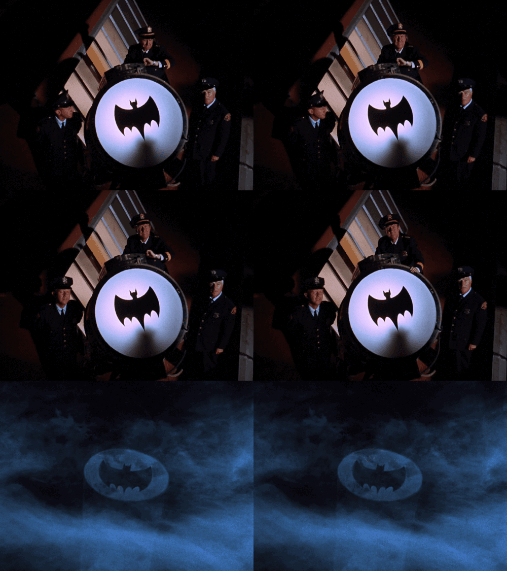
This is a tutorial thread on how to make your own Bat Signal Projector for your Batman Pinball machine. I designed mine with the 1966 style TV Bat Signal logo but you could also change the logo style to fit the 1991 Data East Batman, 1995 Sega Batman Forever, or 2008 Stern Dark Knight. When you are playing your Batman game its way cooler to have a giant Bat Signal projected into your game room while you play.

batsignal.gifbatsignal.gif
keaton.gifkeaton.gif

Stern already makes a great looking Batsignal projector for their Batman66 game but It wasn't going to work well in my low ceiling game room (my Batman topper barely fits). I wanted something that would allow me to have more flexibility in where I could place it. So I started making a list of all the requirements I wanted:

Be reasonably priced
Super flexible mounting options
Projects a really bright image
Have a focusing ability
Be totally reversible with no damage to game
Changeable Logo (Stern Batman66 or Dark Knight, DE Batman, or Sega Batman Forever)
Projected logo can be rotated to any angle
Automaticaly powers up when game is turned on
Doesn't draw power from spike node boards
Plug and Plug for Batman66 LE owners for game controlled on/off projected image

The following tutorial is what I came up with to meet all of those requirements. Its a detailed summary of what I did. Pleae feel free to modify and adapt it to suit your particular needs. If you see areas where you think it could be improved please share your cmments in the thread.

#2 6 years ago

The projector itself is a re-purposed Gemmy Halloween projector. You can still find them on Amazon for around $20.

https://www.amazon.com/Gemmy-Silhouette-Projection-Multi-Function-Multi-Design/dp/B075284L3W/ref=sr_1_5

gemmy (resized).jpggemmy (resized).jpg

I couldn't find any info on them at the www.gemmy.com website so they may be discontinued as its not as fancy as some of the newer ones. There are a ton of similar Halloween and Christmas projectors out there but this one was unique as it had most of the features I was looking for. It was fairly low cost, projects a very bright image, it attaches to a swivel base so its easy to adjust once mounted, It has a focus adjustment, the projected image is on a "slide" that can be pulled out and changed.

This projector is AC powered and has a small circuit board in it that transforms the 120VAC to 3VDC.
Once I opened it up I also noticed that the LED was very big and mounted to a large metal heatsink. There were also multiple lenses in the optics path. I was impressed with the amount of engineering in this little projector.
My original plan was to just use drive the LED directly with a 3V source but when I did that it was not as bright as when using the AC input. I hooked it up to a scope to see what was going on. When using the AC input I was getting a steady 3VDC input to the LED. The current had a saw-tooth profile oscillated between 250ma to 400ma. I then hooked to up to a very high quality DC power supply set to 3VDC. In this arrangment the current draw was a very steady 100ma and the bulb was noticable dimmer. The supply I was was capable of much higher amperage but the LED only draw a small amount. My assumption is that circuit board that converts the incoming 120VAC to 3VDC is also driving the LED in such a way to maximize brightness. Based on this I decided to use the AC input vs a 3VDC input to achieve a brighter image. I'd like to still be able to see the projected image even if the room lights are on. If you wanted to drive the projector with a 3VDC source you could still do that it just wouldn't be as bright.

Projector_ac_vs_dc (resized).jpgProjector_ac_vs_dc (resized).jpg

Another advantage of using the included AC power cord is that it is fused. The plug has a little sliding panel on it. Under the panel is the fuse. It even comes with a spare fuse in there as well. Since this projector was designed to handle outdoor rain and snow I'm assuming that's why the fuse was there. It should never go out in an indoors setup but its nice to have in place just in case.

fuse (resized).jpgfuse (resized).jpg

#3 6 years ago

This projector comes with an assortment of Halloween themed slides like skeletons, witches, ghosts, etc. Each is in a plastic frame that can be opened up. You want to replace the thin film slide with the logo you want to project. I experimented with multiple ways to make the slide.

The simplest and most straight forward way is to print onto clear overhead transparency film (Can't believe this stuff is still around in the digital age). I used some designed for a laser printer as well as an inkjet printer. In both cases the black image I printed was not as opaque as I would have liked. Instead of projecting a black logo it looked smokey gray since it still letting light shine through it.

Another approach was water slide decals. These were also not very opaque but you could put multiple ones on top of one another to make them less translucent. I would cut a piece of transparency film then put the water slide decal on top of it. Then after it fully dried I would put another decal on top of the first decal. With this approach you need to register the decals perfectly on top of each other. If they are off even by a little bit you will notice it once its projected.

The next approach I tried was a die cut adhesive vinyl decal. You use a piece of the clear transparency film as a base then stick the vinyl decal on top of it. This was much more opaque but the edges were not as crisp. There were very tiny bits of adhesive from the vinyl randomly sticking out on the edges. Once projected these were magnified and very noticeable. I tried to clean u the edges but it was very difficult.

The last approach worked the best and was done using laser cut plastic. The logo was entirely opaque and gave a nice sharp edge. For this style you also use a piece of clear transparency film as your base. Then you add the laser cut circular window and logo on top of it. Since the logo is "floating" in the center you need to secure it the the clear film. I found that the ultra thin style "glue dots" worked the best. The ultra thin style keeps the logo flat against the film. the regular glue dots are a bit thicker and the logo sticks up a bit which can cause it to snag when you slide it in or out of the projector. I could only find the ultra thin in a 3/8" size which is a little bigger than the logo. So I had to trim the glue dot slightly. You don't want any part of the glue dot to extend beyond the edge of the plastic logo as it will get magnified and look horrible.

slide parts (resized).jpgslide parts (resized).jpg
glue dots (resized).jpgglue dots (resized).jpg
slide (resized).jpgslide (resized).jpg

A nice benefit of the glue dot is that the logo can be removed and then re-applied. Once you projector is mounted you may find you want to rotate the logo to orient to a slightly different position. You can remove the slide, remove the logo from the slide, rotate the logo to desired position, stick the logo back on the slide, re-install the slide back into to projector.

slide rotate (resized).jpgslide rotate (resized).jpg

The biggest issue with the slide is cleaning any tiny dust particles that may have fallen on it. The clear film is a dust magnet. You need to hold the slide up the to light and check for any little bits of dust on the film and remove them one by one. I found a toothpick with a wet'ed tip works the best. You just touch the dust speck with he tip of the toothpick and it will often stick to it so it can lift it off. Once the slide is free of dust an inserted into the projector it stays pretty clean. If dust does re-settle on it though just pull out the slide and clean it again.

If you see any dust specks in the projected image that doesn't go away from cleaning it might be on one of the the lenses of the projector. I would first clean the slide, then clean the exterior lens. If you still see dust then it might be on one of the the inner lenses. The projector can be disassembled using a #10 Torx driver. There are several lens surfaces that can be cleaned inside. Just use a cloth that is lint free and gently wipe the lens down with some alcohol or eye glass cleaner. It might take several attempts to get the dust speck you are looking for since they are so small and hard to see.

#4 6 years ago

There is a 120VAC source of power in most pinball machines called the service outlet. That outlet is usually active even when the game is powered off. It was designed that way so you could plug in a soldering iron and work on the game even when it was switched off. So for our mod purposes we can't plug the projector directly in there since it would be on all the time.

If you wanted a super simple and cheap install you could just plug the projector into a nearby outlet in your game room. There is no on/off switch on the projector, so if its plugged into the wall, it will be on. Every time you wanted to use the projector you would need to plug it in and then unplug it when you were done playing.

For my setup, I wanted it to come on automatically when the game was turned on. and potentially turn on/off based on game play activity. My solution to this was to use a power relay. There's a whole bunch to choose from and I settled on this one as the best choice for my application.

https://www.amazon.com/Iot-Relay-Enclosed-High-power-Raspberry/dp/B00WV7GMA2/ref=sr_1_1

It made by this company https://dlidirect.com/products/iot-power-relay and you can buy from them directly but their shipping rates are really really high. Amazon is the best price at $30 shipped if you have prime. You can find other relays that do the same thing for a little less but this one has some features I liked: total of 4 outlets, built in circuit breaker, mounting tabs, optical isolation, relay hysteresis and de-bounce protection, and mounting tabs. I think its a very well engineered solid unit for the price.

This power relay works by having an AC input source that will pass through to an AC outlet on the relay when the control trigger is active. The control trigger voltage can be: 3-60VDC or 12-120VAC. In this application the AC input is 120VAC power from your wall, the projector plugs into the output outlet, and the control trigger is wired to your game to tell the relay when to activate the outlet to be on or off. This relay has 4 AC outlets; 1 of the outlet labeled "Always ON" is on all the time, 2 outlets Labeled "Normally OFF" are on only when the trigger signal is active, and 1 outlet labeled "Normally ON" is active when there is no trigger signal and then turns off when there is a trigger signal. There is a red LED indicating power is on and a green LED which comes on whenever a trigger signal is active. When the trigger signal is active there is a "click" when the relay turns on. There is a power switch on the relay as well. Its labeled "OFF" and "Reset". Reset is the same as on. Its labeled reset because it also acts as a circuit breaker. If there is a short or overload in the device you plugged in then the circuit breaker will trip. If this happens you need to push the switch back to reset to turn it back on.

I have already used this particular relay in the past to power mods on my re-theme game Ash Vs The Evil Dead. You can plug 12V or 5V AC adapters or "wall warts" into it and have your trigger signal be any voltage from your game that is on when the game is on (GI bulb for example). Whenever that bulb goes on the relay activates the outlet and your 12V/5V wall warts are on to power your mods. I like using the power relay because it doesn't pull any power from your game boards. The spike system node boards are notorious for being very sensitive so I'd rather not have my mods draw power from them.

iot schematic (resized).jpgiot schematic (resized).jpg

#5 6 years ago

Wiring and Mounting Relay for Batman66 LE Games

The relay installation and wiring is different for a Batman66 LE vs Premium. For LE machines, there is already a connector in the LE topper that has the CPU driven control signal to turn the projector on and off. The signal is there because the SLE owners had the projector built into the topper. Luckily for LE owners Stern left this projector signal connector in all the LE toppers as well.

First step is to mount the power relay. I recommend a different mounting location for LE owners vs Premium owners. For LE owners there are already a lot of wires going through the 1" hole at the top of the back box. You can fit the projector AC cord through the hole but you have to remove all of the topper connections first. Also the control signal to activate the projector is on the outside of the topper, not inside the back box. So for LE owners, I would suggest mounting the relay outside of the back instead of inside it.

The easiest mount location was near the Stern incoming AC power cord. I used one of the mounting tabs on the relay to piggy back it on the bolt that holds the power cord retaining clip on the back of the game. The mounting hole is a little to small for the screw so you need to enlarge it with a 3/16" drill bit. I also added some double stick foam tape on the back of the relay for additional support. You could also use magnets to hold the relay but you need a very strong magnet and I couldn't find an easy way to secure the magnet to the back of the relay reliably. I think the single screw with tape is a simple and effective way to secure it. You could mount he relay in other locations instead (screw it into underside of the game, stick it on top of the back box behind the topper etc). I found this location to be the most convenient.

LE_mounting_bolt (resized).jpgLE_mounting_bolt (resized).jpg
rekaytape (resized).jpgrekaytape (resized).jpg
LE_relay_mounted (resized).jpgLE_relay_mounted (resized).jpg

The relay comes with a small 2' AC power cord. To minimize the number of wires going from the wall to the game I took the Stern AC power cord and plugged that into the AC input socket on the side of the relay. I then ran the small power cord that came with the relay from the "Always ON" outlet to the Stern input AC plug. This way you still only use 1 cord to go from your wall outlet to the game. If you don't want the game power to go through the relay you can just run a separate AC line cord to the relay instead.

LE_mount_AC_in (resized).jpgLE_mount_AC_in (resized).jpg
LE_AC_bypass (resized).jpgLE_AC_bypass (resized).jpg

The Stern provided projector on/off signal connector is under the little black box behind the batman side of the topper. Unscrew the 2 nuts and remove the box to see the connector.

LE_remove_black_box (resized).jpgLE_remove_black_box (resized).jpg

On my game it was just sitting there. In some cases the connector might have gotten back under the center portion of the topper. If so, you might need to unscrew the 4 black screw on the center portion of the topper and remove it to get access to the projector connector.

LE_projector_trigger (resized).jpgLE_projector_trigger (resized).jpg

The Stern connector has 4 pins on it. The black and gray wires are +48VDC to power the Stern projector. The red and yellow/gray wires are the signal to turn the projector on or off. You only need the red and yellow/gray wire to go to the trigger signal input on the power relay. You can either do this via crimp on wire splicing blocks like this:

splice (resized).jpgsplice (resized).jpg

Or you can buy the mating Molex 4 pin connector. I prefer to use the mating connector for a cleaner, easily removable connection. The mating connector you need is a Molex 0003062042 with 0.062" spacing and the pins that go along with it.

LE_trigger_signal_connect (resized).jpgLE_trigger_signal_connect (resized).jpg

Once the connection is made you can replace the little black box. There is a small gap between the center of topper and the black box. there should be just enough space the fit the wire in the gap and then down towards the relay.

LE_trigger_wire_in_gap (resized).jpgLE_trigger_wire_in_gap (resized).jpg

The other end of your connection goes the power relay itself. There is a small green terminal block that unplugs from the relay. You just strip the end of the wires, push them into into the holes and then tighten the screw to hold the wire in. The red wires goes to the "+" side and the yellow/gray wire goes to the "-" side. Then just plug the terminal block back into the relay. Your harness should be about 29" to reach the relay with a little bit of slack.

LE_trigger_in (resized).jpgLE_trigger_in (resized).jpg

#6 6 years ago

Wiring and Mounting Relay for Batman66 Premium Games

My recommended location to mount the relay for the Batman66 Premium games is a different location than for the LE. If you buy the Stern made Bat Signal projector for the Premium version it comes with node boards so their projector will be interactive with game play. Since the Premium models do not come with those topper node boards so there is no existing connector available to tell the projector to turn on/off. My recommended hook up point for the premium owners will turn the projector on when the game is on then turn it off when the game is off. Alternatively, you could hook up the control trigger signal to a specific insert or flasher in the game if you wanted. However I didn't see any insert that came on when the Bat Signal should come on. So I think it was better to just have it on all the time.

Since the trigger signal will be coming from inside the back box I think in the back box is the best location to mount the relay for Premium owners. I would mount it right in the center by piggy backing on top of one the studs used for a cable clamp. I would also recommend a strip of double sided foam tape on the back of the relay for additional support.

premium_mouting_location (resized).jpgpremium_mouting_location (resized).jpg
premium_mounting_nut (resized).jpgpremium_mounting_nut (resized).jpg

You now need a signal to send to the relay so it knows when the game is on. The connector to tap into is CN6 on the power distribution board. It has a 3 pin connector on the board that is active whenever the game is on. The top pin is ground and the bottom pin is +12VDC.

premium_CN6_empty (resized).jpgpremium_CN6_empty (resized).jpg

This connector is used for the Batman66 Stern provided topper and is also used by some other modders (Yelobird's speaker light kit, Pinstadium light kit, etc). If you tap into this connector I'd suggest adding a splice to provide a duplicate 3 pin header. This way if you plug into it you also have a second copy of the pins to plug in something else into it as well in the future. I think the Pinstadium guys already have this splitter on their connector. If you don't plan on using the CN6 connector for more than 1 mod then there is no need to make a splitter. I used a Molex #0009508031 0.156" spacing 3 pin connector with its matching pins to connect to CN6.

premium_CN6_connected (resized).jpgpremium_CN6_connected (resized).jpg

In my breakout header pic below you can see I have black shrink tubing on it. This is to prevent anything from shorting out the +12volt pins.

premium_breakout_header (resized).jpgpremium_breakout_header (resized).jpg

The other end of your connection goes the power relay itself. There is a small green terminal block that unplugs from the relay. You just strip the end of the wires, push them into into the holes and then tighten the screw to hold the wire in. The +12V wire goes to the "+" side and the ground wire goes to the "-" side. Then just plug the terminal block back into the relay. Your harness should be about 13" to reach the relay with a little bit of slack.

premium_trigger_harness (resized).jpgpremium_trigger_harness (resized).jpg

The AC input power to the relay comes from the service outlet. Using the 2' power cord that comes with the relay you can connect that to the AC service outlet on top of the power supply. You also need to get the AC cord for the projector into the back box. The plug for the projector is a litle too big to fit through the 1" hole on top of the back box. You can use an exacto blade to trim the flange around the AC cord so its a little more narrow. Its a very soft rubber so it's was very easy to trim. Even when trimmed its still a very tight fit through the hole but it will fit.

pemium_power_wiring (resized).jpgpemium_power_wiring (resized).jpg

An extra benefit of having the projector trigger to be on whenever the game is on is you now has a second AC outlet available that will only be on when the game is on. You can use this second outlet to plug in a 12V or 5V "wall wart" adapter to power any other mods you have on the game. If you have multiple mods you can hook a power strip up to that outlet and plug multiple adapter into it. Alternatively, you could use just one adapter (make sure it outputs enough amps for whatever mods you'll have) and a power splitter from pinball life like this one to power multiple mods.
http://www.pinballlife.com/index.php?p=product&id=4234

wall wart (resized).jpgwall wart (resized).jpg
splitter (resized).jpgsplitter (resized).jpg

#7 6 years ago

Mounting the Relay for Stern Dark Knight, Batman Forever or DE Batman Games

I don't have any of those games so I'm not sure where the best place to mount the relay would be. I'm amusing they all have wooden back boxes that do not include a pre-drilled hole in the top of the back box like the modern Sterns with metal back boxes do. With a wooden back box it would probably be easiest to just mount the relay via two screws right into the back box. You could wire it to be on when ever the game was on via a GI bulb or if there was a specific insert or flasher that you want to couple the projector on/off with you could connect to that instead. The trigger control wire could be feed through the vent holes in the back or just drill a small hole through an open area in the back box. You just need it big enough to fit two control wires.

The mounting of the projector for Batman66 uses a magnet to hold it to a leg or the metal back box. Since these older games use wooden back boxes the projector mount would work best screwed into the back box via a small wooden plate mounted to the bottom of the projector.

#8 6 years ago

Since the back box on the newer Sterns is mostly metal I decided a magnetic mount for the projector would work best. This way you could stick it anywhere on the top, side, bottom of back box (even on one of the legs) so no matter what your game room looks like you should be able to find a spot that works. If you add an extension cord to projector cord you could even mount the projector on the other side of your game room if you wanted. With the projected mounted farther away it makes a HUGE image.

yuge.gifyuge.gif

#9 6 years ago

You could put it to the entrance of your game room and it would light up when ever the game was on. Lots of flexibility by not having the projector forced to be mounted directly on the machine.

signal_door (resized).jpgsignal_door (resized).jpg

signal_ceiling (resized).jpgsignal_ceiling (resized).jpg

signal_stairwell (resized).jpgsignal_stairwell (resized).jpg

#10 6 years ago

I had to modify the base of the Gemmy projector to add a magnet to it. I choose a very powerful 75 lbs pull force, 1.26" diameter neodymium magnet with a counter sunk hole in the center.

magnet (resized).jpgmagnet (resized).jpg

If you look at the Gemmy base there is metal plate secured by two screws.

magnet1_original (resized).jpgmagnet1_original (resized).jpg

Remove the screws and plate. You will notice a small "cup" recessed in the base.

magnet2_removed_plate (resized).jpgmagnet2_removed_plate (resized).jpg

Its just the right diameter to wedge a #6 nut in there. You may need to tap it in with a small hammer. Once the nut is seated in the cup you can replace the plate you removed.

magnet3_add_nut (resized).jpgmagnet3_add_nut (resized).jpg

You can now attach the magnet via a #6 x 1/2" flat head machine screw. I also put a few drops of locktite on the treads before screwing it in.

magnet4_parts (resized).jpgmagnet4_parts (resized).jpg
magnet5_magnet_added (resized).jpgmagnet5_magnet_added (resized).jpg

The bare metal on the magnet could scratch the finish on the back box or legs so I added some adhesive backed felt to prevent that.

magnet6_felt_added (resized).jpgmagnet6_felt_added (resized).jpg

The ball end of the mount pops into the base of the projector. Once your desired position is chosen tighten the ring on the base to secure it.

projector_adjustments (resized).jpgprojector_adjustments (resized).jpg

Having the magnet mount makes its really easy to tweak the perfect position for the projector. The farther away you are from the wall or ceiling, the bigger the logo will get. If I had the Stern projector with my low ceiling, I would have a tiny image on my ceiling or back wall. With the magnet mount I could stick it all the way at the bottom of my back box to get a decent sized image on my ceiling right next to my game.

projector_leg_mount (resized).jpgprojector_leg_mount (resized).jpg
signal_floor (resized).jpgsignal_floor (resized).jpg
signal_off_side (resized).jpgsignal_off_side (resized).jpg

If you do have high ceilings you can also mount it on the top of the back box as that is metal as well. It's not as small as the Stern version so you might notice it behind the topper if you mounted it on the top.

projector_top_mount (resized).jpgprojector_top_mount (resized).jpg

If you have an adjacent wall you want to project on you could also project straight out out the side . If you did that you would want to remove the slide and rotate the logo 90 degrees so it projects right side up. Once your position is chosen you can focus the image to your liking. I think it looks best when its just a tiny bit out of focus.

#11 6 years ago

Stellar. Make kits and sell them! Profits will be yuge!

#12 6 years ago

For those of you who aren't the DIY type I have made some plug and play kits ready to install. It comes with the projector with modified magnetic base, slide with Batman66 style logo, plug and play harness (specify if you need the Premium or LE version), Power Relay with 2' power cord, full instructions with pictures. Cost is $80 plus $10 shipping. PM me for details and if you need a kit for an LE or a Premium. I will be making slides for the other Batman style logos soon

#13 6 years ago

Cool thread.

Instead of using the relay, you could simply rewire the 110v Stern service outlet to the game switch so it switches on when the game is on. Pretty simple procedure.

rd

#14 6 years ago
Quoted from rotordave:

Cool thread.
Instead of using the relay, you could simply rewire the 110v Stern service outlet to the game switch so it switches on when the game is on. Pretty simple procedure.
rd

I though about that for the premium users who would have it on all the time. I wasn't sure people would feel comfortable messing with the AC wiring or not. But for people ok doing that it saves them the $30 to buy the power relay.

If you have the LE though you still want the relay so the projector will turn on and off when the game play tells it to.

Or you can rip all the AC out of the projector and just drive the LED in it with 3V. It's not as bright that way but some people might be ok with that approach to.

#15 6 years ago

Very clever and super cool you are offering them for sale at a reasonable price.

#16 6 years ago

Beyond Awesome!

Amazing detail and looks to be a nice improvement over the Stern version (which I will just disconnect and leave in place)

#17 6 years ago

Impressive detail ... Great job ...

#18 6 years ago

Awesome job again Doc

#19 6 years ago

Something I didn't think about is the power relay and projector I use fort his mod are designed for US 120VAC. For people outside US you would need some type of transformer to get the right voltage. I'm not sure if 50Hz vs 60Hz would make a difference or not.

2 years later
#20 3 years ago
Quoted from docquest:

Something I didn't think about is the power relay and projector I use fort his mod are designed for US 120VAC. For people outside US you would need some type of transformer to get the right voltage. I'm not sure if 50Hz vs 60Hz would make a difference or not.

Holy threat resurrection batman; but I thought worth adding for the archives. I have doc's light here in the UK - instead of plugging it into the machine I plug it into a step down transformer that then connects to the mains- It works beautifully.

Promoted items from Pinside Marketplace and Pinside Shops!
$ 28.00
Playfield - Toys/Add-ons
ULEKstore
 
18,000
$ 7,995.00
Pinball Machine
Pinball Alley
 
$ 17.95
Playfield - Toys/Add-ons
ULEKstore
 
$ 27.50
Playfield - Toys/Add-ons
The MOD Couple
 
$ 50.00
Cabinet - Armor And Blades
arcade-cabinets.com
 
From: $ 99.99
Cabinet - Other
Lighted Pinball Mods
 
$ 25.25
Playfield - Toys/Add-ons
The MOD Couple
 
$ 79.99
Cabinet - Armor And Blades
PinGraffix Pinside Shop
 
From: $ 99.99
Cabinet - Other
Lighted Pinball Mods
 
$ 18.95
Eproms
Pinballrom
 
$ 27.95
$ 18.95
Eproms
Pinballrom
 
From: $ 5.00
Playfield - Protection
UpKick Pinball
 
$ 5.00
Playfield - Decals
UpKick Pinball
 
$ 27.95
Eproms
Pinballrom
 
10,950 (OBO)
Machine - For Sale
Houston, TX
$ 259.00
32,495
Machine - For Sale
Ontario, CA
$ 144.00
Lighting - Backbox
The MOD Couple
 
3,500 (OBO)
Machine - For Sale
Apex, NC
$ 50.00
Playfield - Protection
Duke Pinball
 
From: $ 15.00
Playfield - Other
YouBentMyWookie
 
From: $ 17.99
Eproms
Matt's Basement Arcade
 
From: $ 115.00
Cabinet - Shooter Rods
Super Skill Shot Shop
 
From: $ 5.00
Cabinet - Other
Filament Printing
 
$ 25.95
Cabinet - Shooter Rods
The MOD Couple
 

Reply

Wanna join the discussion? Please sign in to reply to this topic.

Hey there! Welcome to Pinside!

Donate to Pinside

Great to see you're enjoying Pinside! Did you know Pinside is able to run without any 3rd-party banners or ads, thanks to the support from our visitors? Please consider a donation to Pinside and get anext to your username to show for it! Or better yet, subscribe to Pinside+!


This page was printed from https://pinside.com/pinball/forum/topic/diy-tutorial-batman66-bat-signal-projector and we tried optimising it for printing. Some page elements may have been deliberately hidden.

Scan the QR code on the left to jump to the URL this document was printed from.