(Topic ID: 265757)

Dead flipper

By BroMan90

4 years ago


Topic Heartbeat

Topic Stats

  • 30 posts
  • 4 Pinsiders participating
  • Latest reply 4 years ago by BroMan90
  • Topic is favorited by 3 Pinsiders

You

Linked Games

No games have been linked to this topic.

    Topic Gallery

    View topic image gallery

    Not my photo (resized).jpeg
    20200404_205128 (resized).jpg
    20200404_205206 (resized).jpg
    20200404_191003 (resized).jpg
    Screenshot_20200404-131807_Drive (resized).jpg
    20200401_201806 (resized).jpg
    20200401_201707 (resized).jpg
    #1 4 years ago

    And I come to you guys for help. * Reader alert * I'm a pinball repair noob, this is my first machine and learning as I go.

    So I have a Last Action Hero that's been pretty reliable this past year. Suddenly while playing a few days ago the right flipper randomly stopped working completely (mind you, it has stopped briefly a few times before but came back to life after a short time). Left flipper is fine.

    I've tried my best to do my research, search forums, watch videos but I still cannot diagnose the issue. Here's what I've done and what I know:

    I've checked the simple things. The flipper button switch is good, I can use the right flipper button to eject a ball to trough in diagnostics.

    The flipper mech itself looks good, springs not broken, I can manually flip it smoothly, does not bind or seem to be missing anything.

    End of stroke switch looks good. Touches and opens when it should.

    The wires soldered to the flipper coils seem fine. Theres 2 connections on each coil and they are in tact.

    Moving on to the flipper board. Theres four fuses. I was able to take out F1 and F2 and use my multimeter to test resistance and continuity and they are good. However I cant remove F3 or F4 because they are soldered in?? Is it common for people to solder fuses to the fuse clips? Anyway, I ordered a solder sucker so I can attempt to desolder the fuses and test and/or replace them but according to what I've researched F3 and F4 actually control the working left flipper anyway.

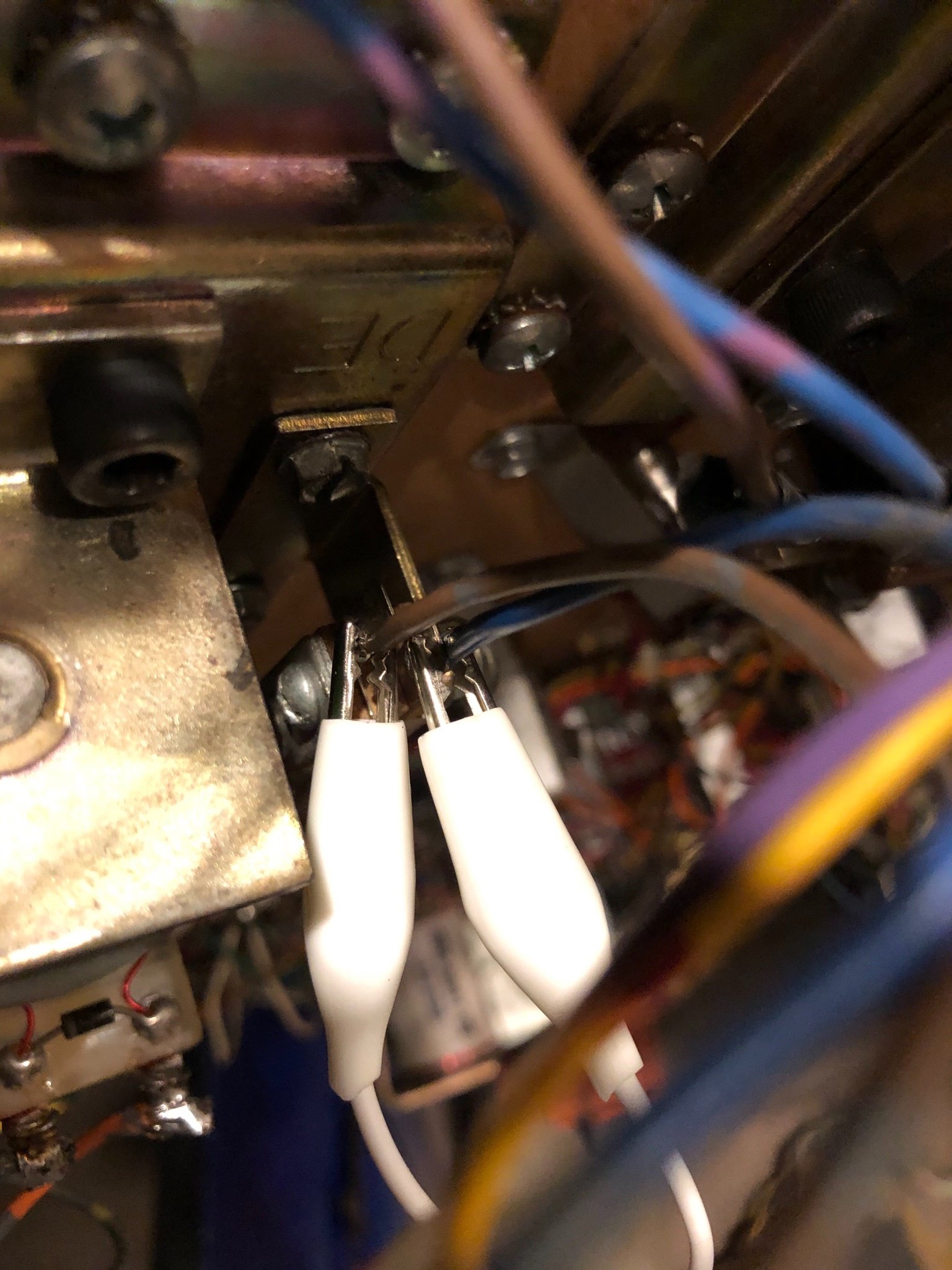
    I've also learned I dont know how to use my multimeter almost at all. To test the coils I believe I should be able to turn the machine on and without starting a game, with my DMM on DC put the black lead to ground and put the red lead to the joint on the coil and it should read 50volt.

    Well...I get nothing on either flipper when I do that, clearly I'm not doing something right. I also wasn't sure what exactly I was suppose to ground to, so I've been touching the black lead to the ground strap in the cabinet.

    Alright pinsiders....please can somebody help me in ways I can understand? This is my only pin and if I cant get it up and running, I dont know if I'll make it through social distancing.

    If it's something that is going to be something beyond my capabilities I fear it may be some time before I can get help here to service it with all the commotion in the world.

    I include a picture of the flipper board if that helps. I know this was long, just trying to document what I was and wasn't able to figure out.

    20200401_201707 (resized).jpg20200401_201707 (resized).jpg20200401_201806 (resized).jpg20200401_201806 (resized).jpgScreenshot_20200404-131807_Drive (resized).jpgScreenshot_20200404-131807_Drive (resized).jpg20200404_191003 (resized).jpg20200404_191003 (resized).jpg
    #2 4 years ago

    Post a picture of the right flipper button switch

    #3 4 years ago

    The fuses in flipper board are soldered in because fuse clips are bad.I would pull fuse f1 on flipper board and test for continuity. On your meter the setting is the first setting to the right of 6 o'clock position.Check that f1 fuse clip has a tight hold on fuse .

    #4 4 years ago

    Also slightly pull on the 2 wires going to your coil and the 2 wires that go to your EOS switch. See if any are loose. Maybe move the wires while trying to use the flipper.
    Then check your diode on your coil, see if it's attached or broken. You'll need to check the diode with a multimeter too.

    #5 4 years ago
    Quoted from pintime:

    The fuses in flipper board are soldered in because fuse clips are bad.I would pull fuse f1 on flipper board and test for continuity. On your meter the setting is the first setting to the right of 6 o'clock position.Check that f1 fuse clip has a tight hold on fuse .

    Just pulled and checked F1 and F2. But have continuity, seem to have a good hold. I had a hard time getting them out the first time in pulled them last night.

    #6 4 years ago
    Quoted from Da-Shaker:

    Also slightly pull on the 2 wires going to your coil and the 2 wires that go to your EOS switch. See if any are loose. Maybe move the wires while trying to use the flipper.
    Then check your diode on your coil, see if it's attached or broken. You'll need to check the diode with a multimeter too.

    I just gave a good tug on all 4 wires, the 2 on the coil and the 2 going to the EOS, seems solid. How do I test the diode? If it's by continuity and touching my leads on one side of the diode and the other...then its good..I suspect that may not be right.

    #7 4 years ago

    Look at your diode and make sure both legs are attached. They often break and are hard to see.

    #8 4 years ago
    Quoted from Da-Shaker:

    Post a picture of the right flipper button switch

    Open and closed.

    20200404_205128 (resized).jpg20200404_205128 (resized).jpg20200404_205206 (resized).jpg20200404_205206 (resized).jpg
    #9 4 years ago

    Your then have to reverse sides with your meter. One direction should show 0 and the other show 70-90 or something.

    #10 4 years ago
    Quoted from BroMan90:

    Open and closed.[quoted image][quoted image]

    The switch should be good if its working in diagnostic. I just wanted to make sure you didn't have a dual/stacked switch.

    #11 4 years ago
    Quoted from Da-Shaker:

    Your then have to reverse sides with your meter. One direction should show 0 and the other show 70-90 or something.

    On what setting please?

    #12 4 years ago

    You have a different meter than me. It should work at the 200ma, I think.

    #13 4 years ago

    Cross check with your right flipper diode

    #15 4 years ago

    If the diodes check ok, then I would check the transistors on the board (Q2 & Q3). Do you have schematics?

    #16 4 years ago
    Quoted from Da-Shaker:

    If the diodes check ok, then I would check the transistors on the board (Q2 & Q3). Do you have schematics?

    I tried checking the diode with my meter on both 200k and 200ma with the game both on/off. Both flippers just read 0 on either flipper so I'm sure I'm doing something wrong. Visually though it seems apparent the diode did not break off on either side and it appears to be identical to the working flipper. I do have the schematics, I just dont understand them very well, but I will start trying to learn how to read them better tomorrow.

    #17 4 years ago

    When you test a diode, you have to switch polarities. 1st you check it with the black on the right side of the diode and the red on the left. Then switch the black and red probes to the other side. You should have different readings.

    #18 4 years ago
    Quoted from Da-Shaker:

    When you test a diode, you have to switch polarities. 1st you check it with the black on the right side of the diode and the red on the left. Then switch the black and red probes to the other side. You should have different readings.

    I've tried, but no matter what and on either flipper when I touch each lead to either side of the diode the MM just says 0.00. Starting to think this MM just sucks. It came in a basic soldering kit.

    #19 4 years ago

    Did you try other settings, like what Pintime was asking you to use before. That might be your diode setting.

    #20 4 years ago

    20k should work too and register 12-13.

    Just in case- the diode is the little black piece that stretches from your blue to orange wire on the flipper coil.

    #21 4 years ago
    Quoted from Da-Shaker:

    20k should work too and register 12-13.
    Just in case- the diode is the little black piece that stretches from your blue to orange wire on the flipper coil.

    I did try other settings, like the continuity setting Pintime suggested to use on the fuse clips. Still, the MM just reads 0.00 on either diode. And yup, I do know the diode is the little piece that goes from the blue to orange wire on the coil. I'm touching one lead on the metal to the left of the black piece and one lead to the right on the black piece. When reversed, still 0.00 even on the working flipper. Doesn't seem to matter if its on 20k, 200k, continuity. I will upload a photo tomorrow to show how I'm testing it. Not sure if I'm that dumb or if I need a different MM. Please tune back in if you could to check my work.

    #22 4 years ago

    I might have sent you down a bad path. I know that with a 3 lug flipper coil, you have to remove 1 leg of the diode in order to test. I thought that if the coil had only 2 lugs you would not have to desolder it, but maybe you do. I'm am just trying to help. There are people on here with far more experience than me. Maybe they'll chime in. Assuming the diodes are good, I would then move on to the 2 transistors, reseat your flipper wiring to the board and check that your F1 & F2 fuse are actually functioning.

    #23 4 years ago
    Quoted from Da-Shaker:

    I might have sent you down a bad path. I know that with a 3 lug flipper coil, you have to remove 1 leg of the diode in order to test. I thought that if the coil had only 2 lugs you would not have to desolder it, but maybe you do. I'm am just trying to help. There are people on here with far more experience than me. Maybe they'll chime in. Assuming the diodes are good, I would then move on to the 2 transistors, reseat your flipper wiring to the board and check that your F1 & F2 fuse are actually functioning.

    I want to believe the diodes are good but without proper MM testing or desoldering I can only see the connections on the coil seem real good. I have only physically disconnected one of the clips to the flipper board to make it easier to remove the fuses, but the other seems solid.

    Thanks for your help this far. I know this forum is full of pinball geniuses that could probably figure it out themselves in 15 minutes.

    Transistors will be a whole new thing I'll have to research how to test.

    #24 4 years ago

    The diode setting is the white mark to right of 6 o'clock,one end of diode must be disconnected to properly test diode.The scale on meter from 6 o'clock to 9 o'clock are resistance readings. I would eliminate the switches as a possibility,check the resistance across closed cabinet switch and closed eos switch you should read less than 1 ohm

    #25 4 years ago

    It sounds like a classic DE EOS switch problem. Take some alligator clips (or just a piece of wire) connect the two leads of the EOS.

    This should make your flipper work.

    Solution 1) bypass the EOS - no harm in this

    Solution 2) https://pinside.com/pinball/forum/topic/data-east-flipper-board-updates

    #28 4 years ago
    Quoted from Jigs:

    It sounds like a classic DE EOS switch problem. Take some alligator clips (or just a piece of wire) connect the two leads of the EOS.
    This should make your flipper work.
    Solution 1) bypass the EOS - no harm in this
    Solution 2) https://pinside.com/pinball/forum/topic/data-east-flipper-board-updates

    Hey jigs, thanks for the help that actually worked. Is that jumper essentially bypassing the eos switch and a something I can use as a longer term fix or is it not a great idea to continue playing the game this way? Thank you.

    #29 4 years ago

    On this particular game, yes it is okay to long term jump it. Just promise you won't do this on any other game.

    You should solder the two wires together or jump the leads together with a soldered wire.

    Please read this, https://pinside.com/pinball/forum/topic/data-east-flipper-board-updates , as this is the reason this is done and the ultimate fix. Other than updating the flipper board.

    Take care my friend and silverball on.

    #30 4 years ago
    Quoted from Jigs:

    On this particular game, yes it is okay to long term jump it. Just promise you won't do this on any other game.
    You should solder the two wires together or jump the leads together with a soldered wire.
    Please read this, https://pinside.com/pinball/forum/topic/data-east-flipper-board-updates , as this is the reason this is done and the ultimate fix. Other than updating the flipper board.
    Take care my friend and silverball on.

    Thank you so much, you saved my sanity.

    Reply

    Wanna join the discussion? Please sign in to reply to this topic.

    Hey there! Welcome to Pinside!

    Donate to Pinside

    Great to see you're enjoying Pinside! Did you know Pinside is able to run without any 3rd-party banners or ads, thanks to the support from our visitors? Please consider a donation to Pinside and get anext to your username to show for it! Or better yet, subscribe to Pinside+!


    This page was printed from https://pinside.com/pinball/forum/topic/dead-flipper-2?hl=broman90 and we tried optimising it for printing. Some page elements may have been deliberately hidden.

    Scan the QR code on the left to jump to the URL this document was printed from.