(Topic ID: 80621)

[Solved] Lethal Weapon 3 Resetting During Gameplay

By Spies

10 years ago


Topic Heartbeat

Topic Stats

  • 98 posts
  • 14 Pinsiders participating
  • Latest reply 10 years ago by popeboy
  • Topic is favorited by 2 Pinsiders

You

Linked Games

Topic Gallery

View topic image gallery

gippb.gif
GI.gif
IMG_20140221_213516.jpg
IMG_20140221_213538.jpg
2011-08-22 22.58.47.jpg
20110822_202909.jpg
20110822_202848.jpg
2011-08-22 19.16.39.jpg
images.jpeg
732.gif
There are 98 posts in this topic. You are on page 2 of 2.
#51 10 years ago
Quoted from Spies:

Damn, thought I was on to something.
When I said ouch from touching the transistor heatsinks under R6 I meant I got a shock from them.
Fuse holders were oxidised but I did clean then up, also used a new fuse, maybe swapping the fuse clips should be the next thing to try.
I do know that running the PSU with nothing plugged into it yielded 9.9vac on both fuse clips but can't comment on if it got hot as at the time that wasn't my focus.

Yeah, some of the circuits on the PSU carry high voltage to run the display. Just a word of caution, there are hazards for novices that are not trained in electronics: damage to your game and personal injury. Don't forget the warning labels - Danger High Voltages inside.

I am lacking sufficient information to help you because you are jumping past some of my questions. This makes it difficult for me to assist you in diagnosing the problem.

#52 10 years ago

Sorry, I wasn't jumping them on purpose, I will check the pin outs on the LM732 and see what happens with various things unplugged in the next couple of days as I've been told I'm "not allowed" to work on it tonight :p

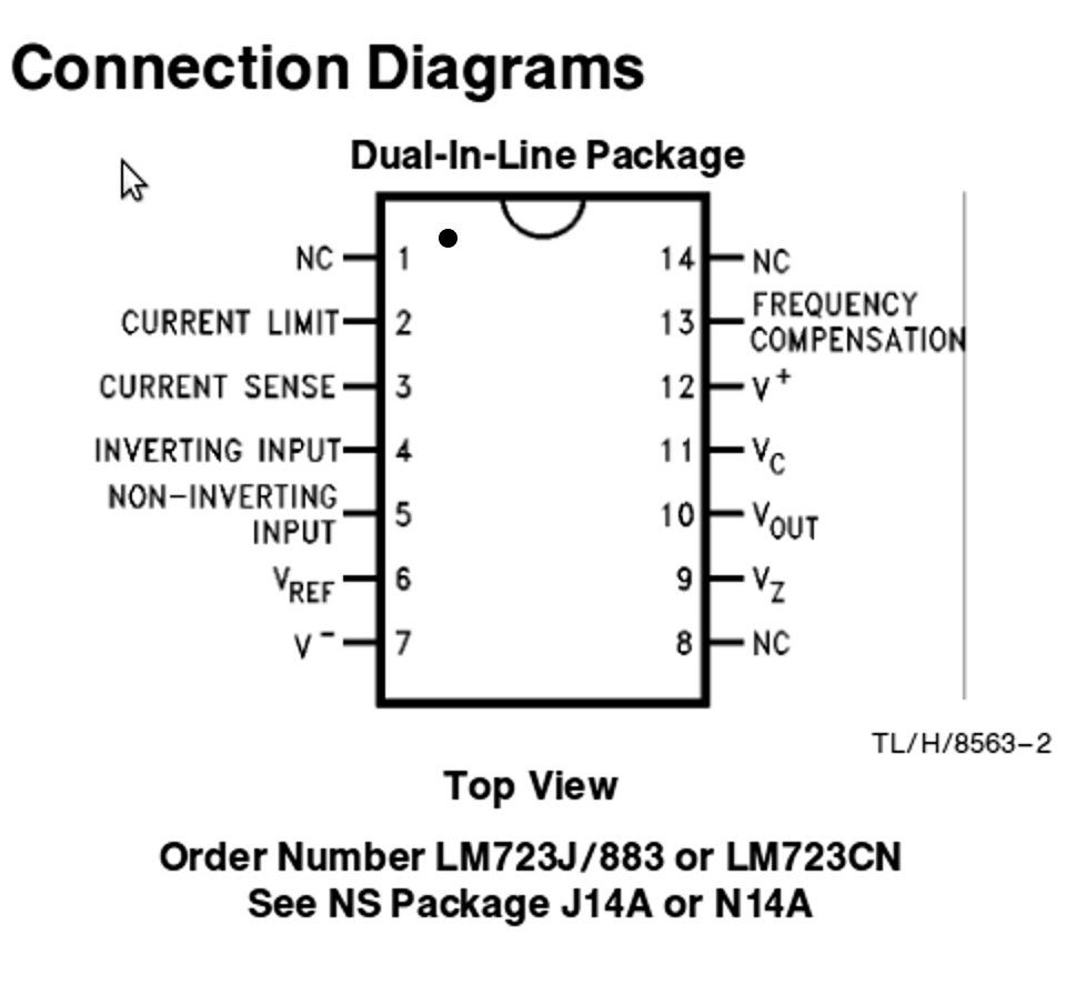
How do I identify the pin numbers on the LM732? Is pin 1 where the recessed dot is?

#53 10 years ago
Quoted from Spies:

Sorry, I wasn't jumping them on purpose, I will check the pin outs on the LM732 and see what happens with various things unplugged in the next couple of days as I've been told I'm "not allowed" to work on it tonight :p
How do I identify the pin numbers on the LM732? Is pin 1 where the recessed dot is?

No problem. For IC pinouts, the recessed dot indicates 1, or the pin to the left of the 'top' of the IC as indicated by a notch. When in doubt go by the datasheet, and never trust labels or silkscreen orientation. The datasheet also gives a lot of helpful information about what is expected at each pin and how the IC operates.

732.gif732.gif

Quoted from Spies:

I've been told I'm "not allowed" to work on it tonight :p

I get in trouble for this all the time

#54 10 years ago

Managed to sneak in 10 minutes of tinkering

I removed all the connectors aside from CN1 CN2 and CN9 (the pigtail) and the fuse did not get warm at all.

I plugged CN6 in and after a few minutes F1 started getting warm again (and there was a 1vac drop across the fuse). I removed the sound board power at the sound board and there's next to no voltage drop.

My attention was drawn to pin 2 on CN6, this appears to be the -12 unreg, pin 2 comes straight off the negative on the bridge. I checked for resistance between the pin and the bridge and I'm reading approx 1ohm.

I tested the regulator and found that both the pins read the same voltage.

#55 10 years ago

You should not be dropping a volt across the fuse, please check the resistance of that fuse and fuse holder together (game off) measuring with your probes on the outside of the fuse holder. This should only be around 3 tenths of an ohm.

CN6 to pin 2, 1 ohm is close enough - I see no problem there.

Regulator test seems good.

Plug in CPU power (CN6 on the PS) but leave CN2 on the sound board off (removing power from the sound board). If F1 still gets hot or pressing the flippers dumps the game, the sound board is not your problem.

#56 10 years ago

Tested resistance across the holders this morning, board is out the machine at this point.

I get 1ohm across F1 but couldn't get continuity at all on F2 until I removed the fuse and re-inserted it, once I did that was also 1ohm. Would the BR be able to function with it only receiving 1 line of 9vac?

I'm replacing the fuse holders to eliminate them anyway.

#57 10 years ago
Quoted from Spies:

Tested resistance across the holders this morning, board is out the machine at this point.
I get 1ohm across F1 but couldn't get continuity at all on F2 until I removed the fuse and re-inserted it, once I did that was also 1ohm. Would the BR be able to function with it only receiving 1 line of 9vac?
I'm replacing the fuse holders to eliminate them anyway.

That's odd, but not uncommon... it sounds like the fuse itself could be broken internally. I would also suggest replacing the fuses with new 7A SB fuses while you're at it.

#58 10 years ago

They're brand new ceramic fuses at the correct rating. The old glass ones that were in exhibited the same heating up problem.

#59 10 years ago
Quoted from Spies:

They're brand new ceramic fuses at the correct rating. The old glass ones that were in exhibited the same heating up problem.

OK...a little baffled at the no continuity comment. Go for the fuse clips, then you can rule those out and continue troubleshooting.

#60 10 years ago

Me too, but if there was no continuity then it would explain why the F2 was ice cold during operation if there was no current going through it?

Would the bridge even be able to rectify the voltage if there were not 2 9vac's going to it?

#61 10 years ago

Both fuses should be ice cold all the time anyway, there is nowhere near 7A+ going through them in regular game operation.

The bridge would partially work as a sort of "half wave" rectifier. Maybe the attached diagram will help to give a visual, one cycle would be present - lose a leg (input ac) on one side and that particular cycle is gone. Beyond that the filtering would have a real hard time smoothing the rectifiers output because of the design

images.jpegimages.jpeg

#62 10 years ago

Fuse holders haven't come yet but the bipolar transistor did so I installed that, whilst I was at it I swapped all the fuses for new (correct) ones.

I now have 4.95vdc at the test point on the PSU, F1 and F2 are around 9.2vac and F1 no longer heats up like it did.

On the MPU I have 4.9vdc at the test point but I'm still getting resets!

I'm at a complete loss now

#63 10 years ago

Ok. Good that the fuse no longer heats up.

Does the reset happen only when one flipper is pressed, only both flippers are pressed, or at other random times?

#64 10 years ago

Its seemingly random now! It reset when the ball dropped through the first 1 of 911.

What would be the least amount of auxiliaries plugged in to start and play a game? I guess just coils and MPU?

I think I'm only going to get to the bottom of it by plugging things in one at a time.

#65 10 years ago

Another thing you can try, clip negative lead of DMM to ground and the positive end of the DMM to the 5V test point on the power supply. Play the game and watch the meter, the voltage should not waver, fluctuate or dip at all. If you see this happen during a reset, you will need more investigation of the power supply.

#66 10 years ago

I've tried that before but I will try again using the scope as it has a higher refresh rate so I'm more likely to see a dip.

I'm going to use a fibreglass pencil and clean up all the header pins best I can, also going to swap the diodes on the coils for new ones incase they're going bad (I've checked and they're all solidly soldered to the lugs).

Other avenue of investigation is the flipper board in the side of the cab.

#67 10 years ago
Quoted from Spies:

Its seemingly random now! It reset when the ball dropped through the first 1 of 911.
What would be the least amount of auxiliaries plugged in to start and play a game? I guess just coils and MPU?
I think I'm only going to get to the bottom of it by plugging things in one at a time.

You have probably checked this already, but anyways.
If there is some kind of connection between the switch of the first 1 of 911 and the flippers,
or there is a bare/semi-broken wire/solder or something like that in close proximity to that switch that are
in line with the flipper wiring..

I assume that a short in that switch (or its near proximity) could cause the pin to reset, that could
also explain the fuses getting hot, right?

If the short is kind of random. The switch it self is could be worn out, or when the switch trigger closes it
could some times touch a screw or another cord or something like that?

What do you guys think?
/mima

#68 10 years ago

Next time I work on it, I will visually inspect for broken wires, the flippers causing it might be a white elephant, it might actually be the vibration from them causing a broken wire to touch something else.

#69 10 years ago
Quoted from Spies:

I've tried that before but I will try again using the scope as it has a higher refresh rate so I'm more likely to see a dip.
I'm going to use a fibreglass pencil and clean up all the header pins best I can, also going to swap the diodes on the coils for new ones incase they're going bad (I've checked and they're all solidly soldered to the lugs).
Other avenue of investigation is the flipper board in the side of the cab.

OK. I just trying to avoid looking elsewhere until fairly certain that the power supply is good and stable. You've made a number of improvements now and things are certainly looking better there. Flipper supply board is worthy of inspection, certainly - I had not suggested looking at it since you said the switch on 911 caused a reset too. Definitely worth banging around, slapping the game with an open hand and seeing if an association can be found between vibration and resets.

#71 10 years ago

Common problem. Mine had it. Burnt connector to power supply board and GI. Also needed a Bridge Rect. replaced on power supply board.

I posted about 2 years ago with pics. PM for more info. Dont give up. Its a great pin.

2011-08-22 19.16.39.jpg2011-08-22 19.16.39.jpg 20110822_202848.jpg20110822_202848.jpg 20110822_202909.jpg20110822_202909.jpg 2011-08-22 22.58.47.jpg2011-08-22 22.58.47.jpg
#72 10 years ago

AV8 has a point. I had random resets related to connectors - my Pinbot would reset, very intermittently, until I found that I could lightly press on the PS to MB connector. Repinned the male and female connector and it was rock solid. Even if you have already done this, I would go back and investigate the all the connectors. It doesn't have to be visually broken, even a slight loss of connection due to a fatigued female connector losing some of its spring tension is all it takes to cause a problem.

As for the power supply, you might consider replacing it altogether. If it ends up not a problem you have a spare now, or can be sold for parts or repair to offset the cost. That's what I did with my Taxi.

It's difficult and annoying when it is very random and hard to duplicate a reset. Sometimes you can find a specific correlation between an event easily, other times not so much. Hang in there, you'll learn a lot about your game and its health along the way.

#73 10 years ago

CN1 often has a pin that fries the whole connector. I had to clean that up once because it was causing resets.

#74 10 years ago
Quoted from Borygard:

In order of common failure for 5V...
CN1
C2
C7
If your issue is the PS, and your game is simply resetting during game play your issue is CN1. C2 and C7 will cause slow or no boots, but not really resets...

--
Rob Anthony
Pinball Classics
http://LockWhenLit.com
Quality Board Work - In Home Service
borygard at gmail dot com

#75 10 years ago

I have no burnt pins or connectors.

Today I changed the diodes on the flippers, swapped out the F1 and F2 fuse holders for brand new ones, used a fibreglass pencil on all the header pins, reflowed solder on the flipper board and still I get resets.

Tried banging on the playfield but that didn't cause any resets.

4.92vdc on a PSU and 4.87vdc on the test point on the MPU

Interestingly however, I started pulling connectors on the driver board (J6 in particular) and things improve dramatically. Granted the kickouts, trough kicker and ball kicker don't work but I can bash the flippers and the machine keeps playing even when I manually launch a ball in to play.

I just pulled the driver board and found some hacks on the back which don't really make much sense to me so I will post it here.

IMG_20140221_213538.jpgIMG_20140221_213538.jpg

IMG_20140221_213516.jpgIMG_20140221_213516.jpg

#76 10 years ago

Those are not really "hacks". Not pretty repairs, but look sufficient. Using jumpers is preferred to a lot of the other methods I have seen weekend warriors do. It looks like they were repairing some burnt GI pins (the three off the fuses). From the pics it looks like the board may need some repinning...hard to see how shiny they are from the pics. Probably the female conn. too, especially the J6 you mentioned.

#77 10 years ago

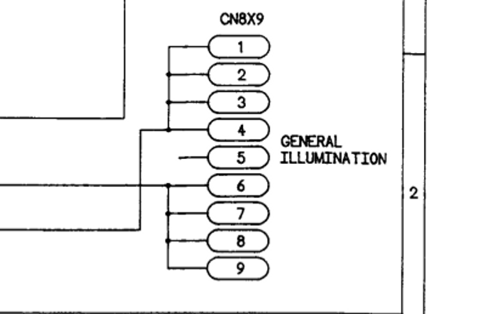
Where the wires have been soldered there is solder connecting all 3 pins. Originally this has 3 separate tracks running to the 3 fuses. Does that matter?

#78 10 years ago
Quoted from Spies:

Where the wires have been soldered there is solder connecting all 3 pins. Originally this has 3 separate tracks running to the 3 fuses. Does that matter?

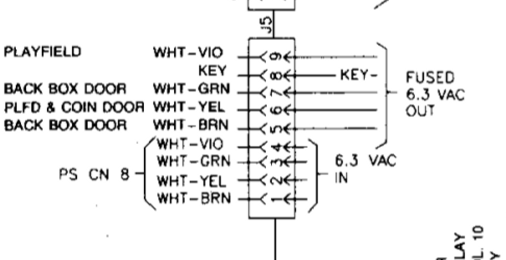
No, it won't matter, they are all tied together at the "input" side to the fuses pins 1 thru 4 at the PS CN8, then the branches are separately fused thru the output pins.

gippb.gifgippb.gif

GI.gifGI.gif

#79 10 years ago

Back to the drawing board then.

#80 10 years ago

Going to borrow a PSU from a TFTC to try in my lethal weapon 3, if that doesn't solve it
It then unfortunately I'm going to have to admit defeat

#81 10 years ago

This has turned into a bit of a monologue but it turns out my friends PSU was hacked, on his PSU wires were soldered directly to the board at CN1 so I couldn't remove it to try it in my machine.

Since then I decided to resolder the thing the transistor pushes in to, after getting the base and emitter the wrong way around twice I decided to swap the wires on the PCB rather than take the heatsink off again.

I also removed the ground jumper from the back of the PSU because it seemed completely pointless.

I now have 4.93vdc at the tp and 4.88vdc at the MPU, it fluctuates slightly but in about an hour or so of play I only experienced 1 reset, so its almost therethere, but how can I squeeze another .1vdc out of it to make it a little stronger?

#82 10 years ago
Quoted from Spies:

I also removed the ground jumper from the back of the PSU because it seemed completely pointless.

Doubling up the ground only improves it's effectiveness, it's ability to carry more current. I would have just left it, there is no reason to remove it.

Quoted from Spies:

I now have 4.93vdc at the tp and 4.88vdc at the MPU, it fluctuates slightly but in about an hour or so of play I only experienced 1 reset, so its almost therethere, but how can I squeeze another .1vdc out of it to make it a little stronger?

Well, that's really not how it works..."squeezing" another tenth of a volt or even more does no good if it is not stable. If the 4.88vdc at the MPU is stable, it should run without resets. When there is a instability the POR circuit is going to reset the game, and that could happen for any number of reasons. The most common causes is a poor cable, a bad supply, failed diodes allowing coil spikes back into the MPU, or a draw on a poor transformer.

Getting another power supply into the game would have helped reduce the possibilities. Did you already repin the PSU to MPU cabling on both the power supply connector and the connector to the MPU? As Rob posted earlier CN1 is the most common cause.

#83 10 years ago

I can't actually afford to re-pin it at the moment, I don't have the tools for crimping molex either.

#84 10 years ago
Quoted from Spies:

I can't actually afford to re-pin it at the moment, I don't have the tools for crimping molex either.

Tools and parts for repinning connectors is a #1 priority for working on pins.

I was going to suggest if you had access to an old desktop PC power supply you could temporarily use it to bypass the games logic power as a test, but you would need to pin the test supply in to CN17 pins 4,5,and 6 to bypass the games logic supply, and then repin the cable afterwards.

#85 10 years ago

Played it again last night and it didn't reset - such a fun game

But yes, re-pinning is definitely next on my todo list.

Thanks for everyones input.

#86 10 years ago

One more thing, what size screw/bolts are used to secure the transistor heatsink on the PSU? 3 out of 4 of my fixings have sheared off

#87 10 years ago

So, its started to reset again, 4.9vdc at the MPU so I'm confident its not that, just over 10mv ripple but when the GI relay and solenoids fire, this spikes as can be seen in the video.

The DC voltage appears to be stable when the resets occur.

Any further suggestions before I scrap this board and buy a new one?

I find if I run the machine with just CN6 connected flipping instantly resets the machine, does that help at all?

#88 10 years ago
Quoted from Spies:

The DC voltage appears to be stable when the resets occur.

Looking at the video, it does not seem to look stable...there's some significant downward spikes there (but I can't tell what your volts per division setting is)
With a scope on mine, at .01V, my waveform is less jagged than your video shows, and the waveform completely stays within .01V, with no downward spikes during flipping.

As long as your diodes have been replaced on the flippers, still looks like a power supply problem to me.

#89 10 years ago

It was set to 10mv/cm

I'm going to borrow a solid state flipper board to see if using a known good one makes any difference.

Can I double check which way the diodes should be? Banded side is on the grey wire.

#90 10 years ago
Quoted from Spies:

It was set to 10mv/cm
I'm going to borrow a solid state flipper board to see if using a known good one makes any difference.
Can I double check which way the diodes should be? Banded side is on the grey wire.

Anode (Non-banded) side of the diode to ORG/GRY on the left flipper, ORG/VIO on the right flipper.
A failing diode even if installed correctly won't divert the induced voltage from the collapse of the coils back to ground properly. It would probably would only be prevalent on one flipper, but can happen to both flippers.

Short circuit diodes that are not obviously damaged show 0Ω or very low resistance in both forward and reverse directions. Sometimes a diode may become "leaky". While its forward resistance may be normal, its reverse resistance may be lower than the expected infinity. Often this fault could only be measured with the diode removed from the circuit it is working in because of the parallel resistances of other components connected across the diode. The coil is a relatively low resistance, so you will have to remove the diode to check, at least lifting one end. Replacing questionable diodes is the best option.

#91 10 years ago

Unfortunately the diodes are installed the correct way around and they are new as I replaced these when I was fault finding.

I know the machine wouldn't normally only be run with CN6 plugged in but I'm guessing it still shouldn't reset? Plugging the rest of the connectors in makes it a little more resilient but inevitably it still goes.

I'm going to seek out a new power supply but unfortunately rottendog and xpin replacements dont seem to be available at the moment in europe.

#92 10 years ago

I have them available, but shipping overseas sucks.

--
Rob Anthony
Pinball Classics
http://LockWhenLit.com
Quality Board Work - In Home Service
borygard at gmail dot com

#93 10 years ago
Quoted from Borygard:

I have them available, but shipping overseas sucks.
--
Rob Anthony
Pinball Classics
http://LockWhenLit.com
Quality Board Work - In Home Service
borygard at gmail dot com

Which one do you stock? What would shipping to UK cost?

#94 10 years ago

Having had another look at the schematics I've found that the flipper board gets its 8vac from cn1-10 and 11 on the power supply, how exactly? Are those wires split before it enters the PSU as 10 and 11 actually carry 9vac into the powder supply to the BR.

I'm thinking if there's a big draw from the flipper board that will make the 9vac dip into the BR and subsequently upset the 5v circuit?

#95 10 years ago

Traced the 9vac and found its not the problem, however, I'm trying to eliminate back current to the MPU being an issue. On CN19, its required for the flipper ground so the flippers function, as a test can I use a jumper wire to ground temporarily?

#96 10 years ago

I got a nice refurbished power supply, things looked to be solved but resets still occur

I've turned my attention to the flippers/solid state flipper board

5.5ohm and 3.8ohm are my flipper coil resistances (right and left respectively).

Transistors on flipper pcb measure (using diode setting) as follows:

Q5 - 970/970
Q7 - 954/945
Q11 - 964/972
Q4 - 968/975
Q12 - 956/945
Q6 - 952/941
Q8 - 867/879
Q1 - 859/870
Q2 - 580/657
Q9 - 589/678
Q3 - 579/596
Q10 - 587/597

Everything looks to be ok there?

1 month later
#97 10 years ago

Resolved by replacing CN6 and the connectors between PSU and MPU.

#98 10 years ago

Glad you figured it out! I feel like I've learned a lot just reading through this whole thread.

Promoted items from Pinside Marketplace and Pinside Shops!
$ 17.50
Playfield - Plastics
Pinball Haus
 
$ 15.00
Playfield - Decals
Metal-Mods
 
$ 15.00
Playfield - Plastics
Pinball Haus
 
3,500
From: $ 40.00
Lighting - Interactive
Professor Pinball
 
$ 1.00
Pinball Machine
Pinball Alley
 
$ 27.95
Eproms
Pinballrom
 
3,995 (OBO)
Machine - For Sale
Rochester, MN
$ 32.00
Electronics
Yorktown Arcade Supply
 
$ 85.00
Playfield - Plastics
Pinball Haus
 
From: $ 9.99
Eproms
Matt's Basement Arcade
 
From: $ 209.00
$ 15.00
Cabinet - Sound/Speakers
Gweem's Mods
 
$ 18.95
Eproms
Pinballrom
 
$ 27.95
Eproms
Pinballrom
 
$ 17.50
Playfield - Plastics
Pinball Haus
 
4,995 (OBO)
Machine - For Sale
Plantsville, CT
3,481 (OBO)
Machine - For Sale
York, NE
$ 28.50
Playfield - Plastics
Pinball Haus
 
From: $ 99.99
Cabinet - Other
Lighted Pinball Mods
 
$ 39.00
Cabinet - Other
Arcade Upkeep
 
$ 18.95
There are 98 posts in this topic. You are on page 2 of 2.

Reply

Wanna join the discussion? Please sign in to reply to this topic.

Hey there! Welcome to Pinside!

Donate to Pinside

Great to see you're enjoying Pinside! Did you know Pinside is able to run without any 3rd-party banners or ads, thanks to the support from our visitors? Please consider a donation to Pinside and get anext to your username to show for it! Or better yet, subscribe to Pinside+!


This page was printed from https://pinside.com/pinball/forum/topic/data-east-power-supply-5v/page/2 and we tried optimising it for printing. Some page elements may have been deliberately hidden.

Scan the QR code on the left to jump to the URL this document was printed from.