(Topic ID: 80621)

[Solved] Lethal Weapon 3 Resetting During Gameplay

By Spies

10 years ago


Topic Heartbeat

Topic Stats

  • 98 posts
  • 14 Pinsiders participating
  • Latest reply 10 years ago by popeboy
  • Topic is favorited by 2 Pinsiders

You

Linked Games

Topic Gallery

View topic image gallery

gippb.gif
GI.gif
IMG_20140221_213516.jpg
IMG_20140221_213538.jpg
2011-08-22 22.58.47.jpg
20110822_202909.jpg
20110822_202848.jpg
2011-08-22 19.16.39.jpg
images.jpeg
732.gif
There are 98 posts in this topic. You are on page 1 of 2.
#1 10 years ago

I'm in the process of rebuilding the 5V side due to the flippers causing a reset of the machine when pressed simultaneously.

I took a voltage reading of 4.8v before the rebuild with the CPU (Rottendog) board connected, what loaded voltage should I be aiming to achieve? If someone could take a reading from their working machine that would be great.

Carl

#2 10 years ago

Is this for your LW3? You should state the game. It may impact peoples response.
faz

#3 10 years ago

Yes, Lethal Weapon 3.

#4 10 years ago

I have a DE Maverick, LW3 has rev. 1 520-5027 PSU and Maverick rev 3, but regardless, yours 5VDC is low. Also check for high AC ripple.

My rock steady all original boards measure at 5V PSU test point, game running:
5.04 VDC, 3.5mV AC ripple.

#5 10 years ago

Also keep in mind, the issue with resets a lot of times is due to a bad filter cap on the +5vdc. You will not see that if you use a DMM on DC voltage, on DC you will see a lower 5vdc value due to the increased ripple. Try setting your meter to AC and check it. You probably see a lot more than 3.6mV.

Regardless, if you getting resets on that game, and it is the original supply, I would replace all the electrolytic caps on the supply before doing anything else. It's cheap and it will most likely fix your problem and a couple future ones.

#6 10 years ago

Are you rebuilding the rottendog, or did you just put it in as a test; a little confused.

Robert

#7 10 years ago

The MPU is a Rottendog board, I included that information incase it is more sensitive to 5vdc being a little low.

#8 10 years ago

Sorry, just not awake yet I guess.

I don't think the RD is more sensitive, I would expect the opposite, being a lot newer parts and design.

You really need to get the PS at 5v.

I had a bad RD power supply that read 5v until I loaded the output, then it dropped to something like 4.2v. I hooked a volt meter to the PS and when the machine started to not work correctly saw that the output was low.

I sent it back and Jim sent me a new one.

So the PS can be bad and not really show it, if you just hook up a DMM.

Robert

#9 10 years ago

It also makes a difference where you are measuring. Check the 5VDC at both the PS and the CPU board to rule out loss from bad cables or connectors, you might lose a couple tenths of a volt through a cable.

Any problem with regulation or filtering in the PS can cause resets, regardless of which CPU you are using. Check your ripple on the PS test point for 5VDC, and if DC is too low or ripple is too high then repair or replace the PS.

#10 10 years ago

The MPU is Rottendog, I see no where where the PS was called out as a Rottendog.

Again, if it is the ORIGINAL supply that's never been reworked, do a cap job.

#11 10 years ago

Whilst I'm waiting for parts to arrive I was testing the resistors in the 5v circuit, R4 and R5 check out OK but R6 is giving a strange reading, maybe because its in circuit? With the meter on 200 ohm scale it reads between 3 and 7 ohms, it should be 0.12 according to the schematic.

Any thoughts?

#12 10 years ago
Quoted from Spies:

Whilst I'm waiting for parts to arrive I was testing the resistors in the 5v circuit, R4 and R5 check out OK but R6 is giving a strange reading, maybe because its in circuit? With the meter on 200 ohm scale it reads between 3 and 7 ohms, it should be 0.12 according to the schematic.
Any thoughts?

You must lift one leg of each resistor you are measuring for accuracy, otherwise you are potentially measuring the resistance of other components elsewhere in the circuit. What is 0.12? 12 tenths of an ohm? 0.12K ohm? please remember to include units of measure in your description.

#13 10 years ago

There's no unit on the schematic, I assume its 12 tenths of an ohm?

#14 10 years ago

replace the C2 cap (100 mfd) on the DE power supply. It is right next to the large heat sink.

#15 10 years ago
Quoted from Spies:

There's no unit on the schematic, I assume its 12 tenths of an ohm?

You might have just overlooked: there's a note at the bottom of the schematic:

- all resistor values in ohms, 5%, 1/4w unless otherwise specified
- all capacitor values in microfarads unless otherwise specified

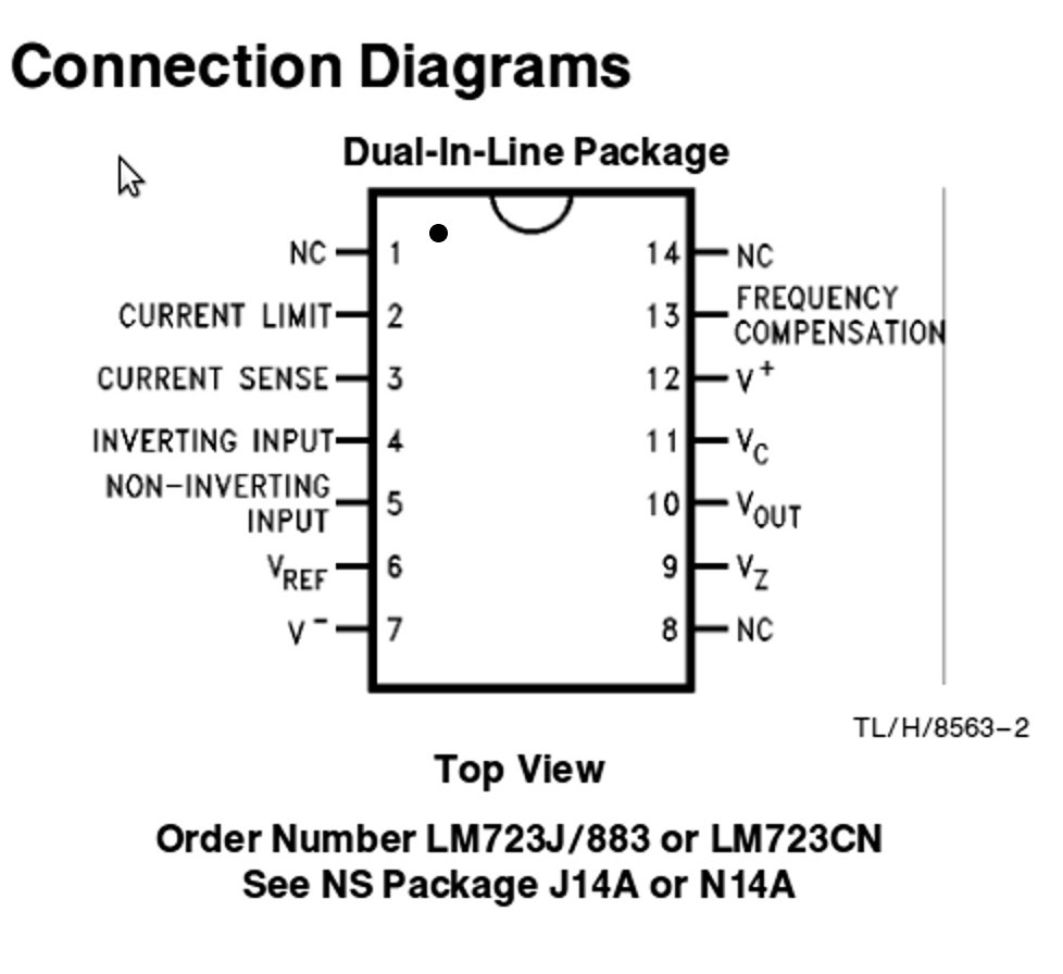
cfh is correct, replace the C2 cap. It is the first component to suspect. Another common cause for loss of 5VDC power is failure of the LM723 regulator. Measure and compare the DC voltage at pins 4 and 5 of the regulator relative to board ground. If the voltages differ, the regulator has failed. Socket and replace the regulator. (from PinWiki)

#16 10 years ago

Thanks all, will give it a go and report back, checking for ripple is something I hadn't thought of too.

#17 10 years ago
Quoted from wayout440:

You might have just overlooked: there's a note at the bottom of the schematic:
- all resistor values in ohms, 5%, 1/4w unless otherwise specified
- all capacitor values in microfarads unless otherwise specified
cfh is correct, replace the C2 cap. It is the first component to suspect. Another common cause for loss of 5VDC power is failure of the LM723 regulator. Measure and compare the DC voltage at pins 4 and 5 of the regulator relative to board ground. If the voltages differ, the regulator has failed. Socket and replace the regulator. (from PinWiki)

I've fixed a ton of DE power supplies. Never once, and i mean never, have i had to replace the voltage regulator. I'm sure it goes bad, but again i've never seen it happen.

C2 is the main culprit. Followed by the +5 filtering caps, and then the connectors. But DE changed their design after the alpha numeric years to use three smaller caps tied together to get about 15,000 mfd. this is a really good design change, and i rarely see that fail. (The older 18,000 single cap dies a fair amount.) But on LW3 this is the newer design. So in order of "things that go bad" i would say C2 followed by the input connector cn1 (power from the transformer to the power supply.)

If i have a DE power supply for repair (say GI connector, which is really common), i replace C2 just as a rule now. It's right next to a big and often warm heat sink. It just bakes the C2 cap (which is 100 mfd and about 20 cents.) So it gets replaced as a rule. That cap is in series in the circuit, so when C2 goes, the whole 5 volts goes down.

#18 10 years ago

+1 and if you look close at it a lot of times it 'pisses' out the bottom and your see a spot on the board.

#19 10 years ago

Email the guys at Rottendog. I had an issue with my DE power board, they repaired it. Zero problems since.

#20 10 years ago

One would only email them if it were a Rottendog P/S,,, which it has never been stated it was.

It was stated it was a Rottendog MPU.

#21 10 years ago

Oh sorry, my bad.

#22 10 years ago

In order of common failure for 5V...

CN1
C2
C7

If your issue is the PS, and your game is simply resetting during game play your issue is CN1. C2 and C7 will cause slow or no boots, but not really resets.

4.8V out of the PS is fine though. And although not as common as the above parts, the regulator IC does go, but again, not your issue here.

--
Rob Anthony
Pinball Classics
http://LockWhenLit.com
Quality Board Work - In Home Service
borygard at gmail dot com

#23 10 years ago
Quoted from Borygard:

4.8V out of the PS is fine though.

...not if the ripple voltage is out the window.

For some reason, we can't seem to get a confirmation on the numbers though. It also takes only a few seconds to check the ripple, and the regulator and confirm its accuracy. But folks would rather suggest to just throw parts at the thing until it works. That's just not how I troubleshoot.

#24 10 years ago

I got a friend with a TFTC to check his 5v line, its over 5 volts load so its pretty safe to say I have a problem.

Not all parts have turned up so I haven't tackled it yet.

#25 10 years ago

I've replaced C3, C2, C1 and DB1 and I now have 4.95v on TP1. I haven't replaced TR5 yet as it hasn't arrived.

I tested ripple but I'm not sure I'm doing it right, on a 200v A/C scale it's coming out as 10v, I'm guessing thats pretty terrible?

The machine is still resetting when both flippers are spammed and it can actually get itself in to a state where the blanking light goes out, the music/dmd is still running but no coils or buttons work.

#26 10 years ago

Also checked CN1, pin 10 is getting 8.9vac and pin11 is receiving 9.9vac, should they not be the same?

#27 10 years ago
Quoted from Spies:

Also checked CN1, pin 10 is getting 8.9vac and pin11 is receiving 9.9vac, should they not be the same?

That's not so much a concern as what is your output from the bridge - measure both VDC and ripple compared to #2 below. Of more concern, is the regulator getting fed smoothed DC from the output of the bridge?

1. CN1 10.3 VAC on pin 10 and 10.9 VAC on pin 11.
Unloaded (connector removed, measured across CN1 pins 10 & 11) = 10.5VAC .

2. Output from the bridge (measured at +12V unregulated TP) = 10.5 VDC, ripple .36 VAC.

3. Output from the regulator, measured at R6 is = 5.4 VDC

4. Final smoothed output @5VDC TP = 5.04 VDC

Can you put your meter on a lower A/C scale so you can get better resolution? With 10 VAC A/C of ripple and the primary filter caps already changed I would guess that your bridge rectifier is not well.

#28 10 years ago

i had a DE power supply( jurassic park) with very low 5 volts. Ac input was correct, caps were not the problem. looking at the datasheet, the LM723 requires 12V at one of the pins. the 12 v was missing. DE ran the ac input thru some diodes and resistors on the board. rather than go thru it, i pulled 12v from the power supply's 12v bridge rectifier for the lm723 input and have a rock steady 5 v. just make sure you cut the trace feeding the lm723. been working for yrs.

-1
#29 10 years ago
Quoted from pinnut:

i had a DE power supply( Jurassic Park) with very low 5 volts. Ac input was correct, caps were not the problem. looking at the datasheet, the LM723 requires 12V at one of the pins. the 12 v was missing. DE ran the ac input thru some diodes and resistors on the board. rather than go thru it, i pulled 12v from the power supply's 12v bridge rectifier for the lm723 input and have a rock steady 5 v. just make sure you cut the trace feeding the lm723. been working for yrs.

The MC1723 (LM723) requires the 12VDC at both pins 11 & 12. This "hack" you did will only work if the bridge output is o.k., I have my doubts about that in this case, but it can be checked. It's also just two caps and two diodes you bypassed that serve as a rectifier for supplying the MC1723s Vcc and Vc pins. I'm not sure why you couldn't just fix this correctly, but I guess it worked for you. IMO it would be better if the OP does some more troubleshooting before adding jumpers and cutting traces.

#30 10 years ago

Read 4.7 for the 723 regulator on DE boards here:
http://www.pinwiki.com/wiki/index.php?title=Data_East/Sega#Power_Supply_Issues
Covers voltage doubler section mentioned above. Due to its location, would be a good idea to replace C2 with a high temperature cap.
If you get an abnormal voltage on ripple voltage reading - retry measurement using an old fashioned analog meter. Some digital meters do a poor job with this sort of measurement and give you phantom readings. Can never get a phantom reading from an analog meter.

#31 10 years ago

I was looking for that theory of operation...couldn't remember where I had seen it. Thanks!

#32 10 years ago

+12 unreg = 12.2v
R6 = 5.02v (seems low compared to yours)

Setting DMM to 200vac and probing the 12v test point gave me a reading of 25.9

#33 10 years ago

That R6 at only .2 of a volt low should not be a problem at all. My 12V test point measures 322 mVAC (.322VAC) with my Fluke auto-ranging DMM. If you don't have a lower range than 200VAC, perhaps your decimal point is not working? Perhaps try another meter like G-P-E said. You might be o.k. now with all the caps changed. Game playing well?

#34 10 years ago

Still resetting when both flippers are pressed in quick succession.

When I measure the the VAC at F1 and F2 without a load, both read 9.9vac, with the PSU under load only 8.5VAC is read at F1 and the fuse is getting quite warm, something on CN6 is pulling it down.

I seem to be experiencing random switch and solenoid issues too, whether that's down to the PSU I don't know.

I will try and borrow an analogue multimeter as the resolution in mine is only down to 100mvac.

#35 10 years ago

Fuse clips good? Check (or replace) bridge rectifier.

#36 10 years ago
Quoted from wayout440:

If it were me, I would check/replace the bridge rectifier.

Its been replaced (DB1).

#37 10 years ago
Quoted from Spies:

I will try and borrow an analogue multimeter as the resolution in mine is only down to 100mvac.

So all you have is a 200VAC and a 100mVAC setting?, nothing between those?

#38 10 years ago

The only AC scale I have is 500v (1v resolution) and 200v (100mv resolution).

When testing for ripple should I be placing the common on ground?

Managed to borrow an oscilloscope so we will know once and for all!

#39 10 years ago
Quoted from Spies:

The only AC scale I have is 500v (1v resolution) and 200v (100mv resolution).
When testing for ripple should I be placing the common on ground?
Managed to borrow an oscilloscope so we will know once and for all!

OK. Yes, ripple is measured with the common on ground. With a scope, clip the common probe lead to ground, and probe the points you wish to measure. With a scope you can view and measure the ripple on the AC setting, or you can view it on DC setting as a sine wave "riding" on top of the DC.

With that fuse getting hot, I wouldn't be surprised if something else was getting hot...although this is not always the case. Have you carefully touched some of the other components such as the regulators and see if any of those are getting hot?

#40 10 years ago

As I'm a bit new to this, just confirm theres only one regulator on the PSU - the LM732?

#41 10 years ago
Quoted from Spies:

As I'm a bit new to this, just confirm theres only one regulator on the PSU - the LM732?

Sorry, yes... location IC1 it is a LM732 (or MC1723CP). It regulates TR5 2N6057 power transistor.

PinWiki section:

4.7.3 Low 5VDC and game resets

If you have a low +5v, you'll experience game resets, especially when pressing the flippers during multiball. A 'shotgun' repair would be to replace...

bridge rectifier (DB1, CM3501),
C2 (100uf 25v),
C3 (47uf 63V),
C7 (330uf 25V),
LM723 voltage regulator,
TR5 (2N6057) on the power supply board (use 2N6059 or 2N6284 to replace obsolete 2N6057),
C1 (1000uf 25V) can also be replaced when you have problems with the -12V supply too.

Most times, this will correct problems with the 5VDC power supply

#42 10 years ago

Scope shows just over 10mvac ripple, whilst testing the machine got stuck in a sound loop and the outhole and ball launch coils now wont fire.

#43 10 years ago
Quoted from Spies:

Scope shows just over 10mvac ripple, whilst testing the machine got stuck in a sound loop and the outhole and ball launch coils now wont fire.

Ripple is much better than what you were reporting earlier in the thread, that's good.

Do you mean the outhole and ball launch coils are not working at all, even after a game reboot? or did they just stop working when you were testing? (Not sure if this is related at this time)

PinWiki check of the LM723:
Another common cause for loss of 5VDC power is failure of the LM723 regulator. Measure and compare the DC voltage at pins 4 and 5 of the regulator relative to board ground. If the voltages differ, the regulator has failed. Socket and replace the regulator.

Another quick check: set meter to dc, probes on to ground and 5VDC test point and then fire the flippers to see what effect that might be having on the logic supply.

#44 10 years ago

5vdc is solid even when flippers are being pressed 5v led on MPU stays lit the whole time just the blanking LED goes out when it restarts.

All diodes appear to be present on solenoids too so its not back current confusing the MPU.

Can I unplug the sound board completely to try and isolate that as a cause?

#45 10 years ago

OK the blanking is just doing it's job to protect the MPU. What concerns me most is the fuse getting warm. None of the fuses should be getting warm, the only items that should be getting warm after the game has been running for 5-10 minutes is the large white cement power resistor R6, the bridge rectifier, and the power transistor on the big heat sink. Everything else should be cold, or barely perceptible as warm.

Yes you can unplug the sound board. Do some checks of the PS temps and voltages with the sound board disconnected. Then do the same thing with the MPU power disconnected. I'm not certain that your problem is with the PS, since you mentioned those coils not working.

I would also suggest after that to go back and check the regulator IC LM723 pins 4 and 5 as I posted earlier, to make sure that is working, and touch it to see if it is warm/hot, it should not even be warm.

#46 10 years ago

Just left the machine on for 10 minutes. F1 fuse is too hot to hold. Bridge rectifier on PSU is getting warm, R6 is getting slightly warm and U20 on sound board is getting warm.

Oh and the heatsinks on the transistors pack a punch, ouch! Hand is still tingling.

As only 1 fuse gets hot it wouldn't it suggest the problem is the bridge? As the load would be shared if the bridge was working correctly.

How about resistance on the traces being a problem? Might it be worth jumpering with wire to the leg of the BR?

#47 10 years ago
Quoted from Spies:

Just left the machine on for 10 minutes. F1 fuse is too hot to hold. Bridge rectifier on PSU is getting warm, R6 is getting slightly warm and U20 on sound board is getting warm.
Oh and the heatsinks on the transistors pack a punch, ouch! Hand is still tingling.

F1 too hot to hold - that's not right. Bridge rectifier warm, but not burn your finger hot is ok. R6 slightly warm is ok, that's why it is a wirewound resistor, it is expected to throw off a lot of heat. Not at my game so I can't really comment on U20...may or may not be normal. Heatsinks on transistors - which ones? I doubt any should be burning you. Please be careful when checking components this way - you don't want a serious burn.

My question is - does the fuse f1 get that hot with the sound board or MPU disconnected? What about my other suggestion about the LM723 regulator, have you checked it yet?

Quoted from Spies:

As only 1 fuse gets hot it wouldn't it suggest the problem is the bridge? As the load would be shared if the bridge was working correctly.

The 1 fuse getting hot can be anything past the fuse in the circuit, up to and including the fuse. Oxidized or poor soldered clips and dirty glass fuses can cause the fuse to get hot. But taking all you have said up to this point, and assuming you have checked the fuse and holder, I doubt that is your problem. You said you replaced the bridge, so that's less likely now. There's still more in the power supply to check, but other boards can be drawing current if there is problems with them, so it is wise to check the power supply first with no load/no boards connected to it. Whenever I aquire a new 'used' game, I always disconnect everything from the power supply and verify it is working the way it should before connecting up the other boards.

Quoted from Spies:

How about resistance on the traces being a problem? Might it be worth jumpering with wire to the leg of the BR?

Essentially a trace is a wire, a very low resistance. It should not be a problem, unless for some reason you suspect damaged traces. They can be verified with your DMM for low resistance. Otherwise, that is pretty much a wild guess and put near the bottom of the list of possible problems here.

#48 10 years ago

I just had the idea of checking to see if F1 and F2 have continuity to ground. And they do!

Pretty sure they shouldnt ? I tried bending the board away from the backplate in case it was shorting but it doesn't appear to be.

I will do some more checks tomorrow, its late here now. You've been a massive help so far though thank you.

#49 10 years ago
Quoted from Spies:

I just had the idea of checking to see if F1 and F2 have continuity to ground. And they do!
Pretty sure they shouldnt ?

Yes, this is normal. The transformer is fooling you.

#50 10 years ago

Damn, thought I was on to something.

When I said ouch from touching the transistor heatsinks under R6 I meant I got a shock from them.

Fuse holders were oxidised but I did clean then up, also used a new fuse, maybe swapping the fuse clips should be the next thing to try.

I do know that running the PSU with nothing plugged into it yielded 9.9vac on both fuse clips but can't comment on if it got hot as at the time that wasn't my focus.

Promoted items from Pinside Marketplace and Pinside Shops!
$ 27.95
Eproms
Pinballrom
 
From: $ 209.00
$ 15.00
Playfield - Decals
Metal-Mods
 
$ 17.50
Playfield - Plastics
Pinball Haus
 
$ 17.50
Playfield - Plastics
Pinball Haus
 
From: $ 9.99
Eproms
Matt's Basement Arcade
 
$ 5.00
Playfield - Protection
UpKick Pinball
 
$ 18.95
$ 27.95
Eproms
Pinballrom
 
3,377 (OBO)
Machine - For Sale
York, NE
From: $ 159.95
Cabinet - Sound/Speakers
PinSound
 
From: $ 99.99
Cabinet - Other
Lighted Pinball Mods
 
4,995 (OBO)
Machine - For Sale
Plantsville, CT
2,500 (OBO)
Machine - For Sale
Milwaukee, WI
3,995 (OBO)
Machine - For Sale
Rochester, MN
$ 15.00
Playfield - Plastics
Pinball Haus
 
$ 18.95
Eproms
Pinballrom
 
$ 1.00
Pinball Machine
Pinball Alley
 
From: $ 40.00
Lighting - Interactive
Professor Pinball
 
$ 32.00
Electronics
Yorktown Arcade Supply
 
$ 85.00
Playfield - Plastics
Pinball Haus
 
$ 28.50
Playfield - Plastics
Pinball Haus
 
Great pinball charity
Pinball Edu
There are 98 posts in this topic. You are on page 1 of 2.

Reply

Wanna join the discussion? Please sign in to reply to this topic.

Hey there! Welcome to Pinside!

Donate to Pinside

Great to see you're enjoying Pinside! Did you know Pinside is able to run without any 3rd-party banners or ads, thanks to the support from our visitors? Please consider a donation to Pinside and get anext to your username to show for it! Or better yet, subscribe to Pinside+!


This page was printed from https://pinside.com/pinball/forum/topic/data-east-power-supply-5v/page/1 and we tried optimising it for printing. Some page elements may have been deliberately hidden.

Scan the QR code on the left to jump to the URL this document was printed from.