(Topic ID: 318938)

Cocktail Table Homebrew! (theme TBA)

By zacaj

1 year ago


Topic Heartbeat

Topic Stats

  • 122 posts
  • 19 Pinsiders participating
  • Latest reply 12 months ago by slochar
  • Topic is favorited by 28 Pinsiders

You

Linked Games

No games have been linked to this topic.

    Topic Gallery

    View topic image gallery

    pasted_image (resized).png
    pasted_image (resized).png
    pasted_image (resized).png
    ezgif-3-1584ddac51.gif
    ezgif-3-b31d4fea8c.gif
    pasted_image (resized).png
    pasted_image (resized).png
    pasted_image (resized).png
    pasted_image (resized).png
    pasted_image (resized).png
    pasted_image (resized).png
    pasted_image (resized).png
    pasted_image (resized).png
    pasted_image (resized).png
    1718452C-6993-4D83-9F43-150E244B227F (resized).png
    pasted_image (resized).png

    You're currently viewing posts by Pinsider zacaj.
    Click here to go back to viewing the entire thread.

    11
    #1 1 year ago

    After wrapping up development of Poker (https://pinside.com/pinball/forum/topic/pinball-poker-poker-time-undecided-poker-themed-homebrew), I began the planning phase for my next homebrew, and am now starting with some actual development.

    Originally my plan was to attempt to make a more complex, modern game with ramps, habitrails, toys, etc, but as I finished up Poker (and attempted to maintain it afterwards), many of the issues I encountered convinced me that I shouldn't dive straight into something so complex without getting the 'basics' down more, so I decided to try to make a cocktail first, since it'd have to end up being a simpler game due to the space constraints. I also feel like cocktails are a good area to explore, as there haven't been any made in a long time, and none follow more modern design sensibilities.

    To start, I acquired a parts machine, originally a Roy Clark The Entertainer, to use as a cabinet. pasted_image (resized).pngpasted_image (resized).png

    One of the big issues I ran into with Poker was with the CAD. I originally designed the playfield in CAD, but then cut it from plywood by hand, and had to make numerous modifications as I went. My original CAD ended up out of sync with my physical playfield, and caused all kinds of problems. This time, I want to get the playfield CNC cut directly from the CAD, and also model everything in more detail from the start to try and avoid other issues down the line, so I started by modeling both a simple playfield and cabinetpasted_image (resized).pngpasted_image (resized).pngpasted_image (resized).pngpasted_image (resized).png

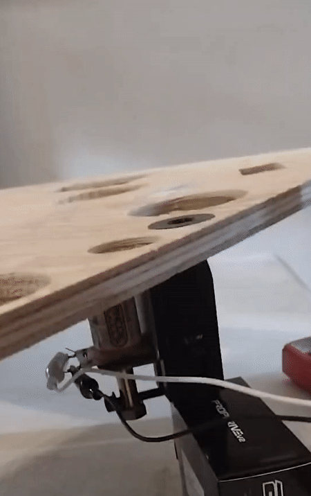
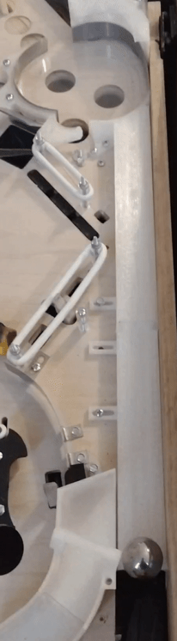
    When designing, especially in a situation where the playfield will be CNC cut and I want to do everything in as few iterations as possible, I try to identify any potential risks as early as possible, and prototype them out first. Since I want to have a more modern game style, but can't have ramps due to the size of the cabinet, I decided I'd like to have a subway, with exits that feed the flippers, instead. This will also be good practice at both constructing subways in general, as well as with more custom mechanisms/etc. Sadly, I immediately discovered an issue thanks to the CAD modeling: pasted_image (resized).pngpasted_image (resized).png
    That's the plunger for the VUK, sticking out the bottom of the cabinet. VUKs in general are already pretty tall, and it only gets worse when you need to also have a subway feeding them, and that subway needs to clear other mechs on the bottom of the playfield. The entire cabinet is only 9" deep, and even after trying to squash a typical mech down as much as possible, it was still 7". Then I realized that the original playfield mounting brackets only put the playfield at 3.5 degrees, not the 6.5-7 that a newer game would have, which constrained the area under the playfield I had to work with down to only 4"!

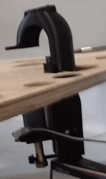
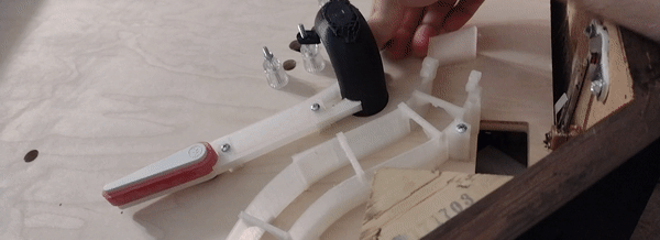
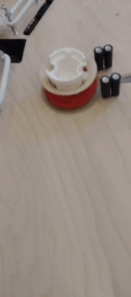
    So now I've designed a new mech, which isn't like any VUK I've seen before, where the coil and plunger are mounted adjacent to the ball instead of below it:pasted_image (resized).pngpasted_image (resized).png

    I'm not sure if there's a reason why this style of design is never used or not. The closest I can think of are bally linear slingshots. I've heard a lot of bad things about bally's linear flippers, but not much about the slingshots, so maybe they're fine? I assume the disadvantage of this approach is that the force on the plunger won't just be along its axis, but will also be twisted somewhat to the side, but I'm not sure how much that'll matter. Most of the mechanism is designed to be 3D printed, but the coil bracket and plunger will still have to be metal. Hopefully having a metal bracket screwed to the plastic body will be enough to hold it together.

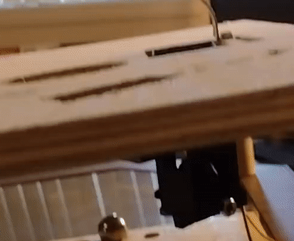
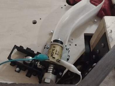
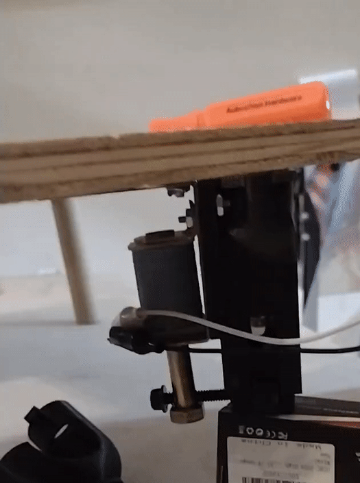
    Since this is a custom bracket, I don't really have any easy way to get it made, so I end up having to use a thinner sheet of steel than is common on pinball machines, and bend it using my harbor freight hand metal brake. This doesn't produce perfect 90 degree angles, and it's hard to get the bends exactly int he locations you want, but at least they come out nice and cleanpasted_image (resized).pngpasted_image (resized).png

    I was unable to find a source of plunger material locally, so I ended up using a 7/16" bolt that was long enough that the threads left a smooth part that fit my needs, and then I ran a 1/4" bolt through it sideways to connect it to the platform the ball rests on. I'll need to clean it up a bunch, and maybe consider tapping a smaller hole vs just running the bolt through, but I think it should be sufficient for a proof of concept. pasted_image (resized).pngpasted_image (resized).png

    My first attempt doesn't go too well. The ball barely makes it out of the VUK, not even fully clearing the playfield:
    ezgif-2-2112bef05a.gifezgif-2-2112bef05a.gif
    But then realize I'm using the wrong coil, and swap to a 23-800, which is what sterns use in their VUKs, and it goes much better:
    ezgif-2-3ce7524772.gifezgif-2-3ce7524772.gif

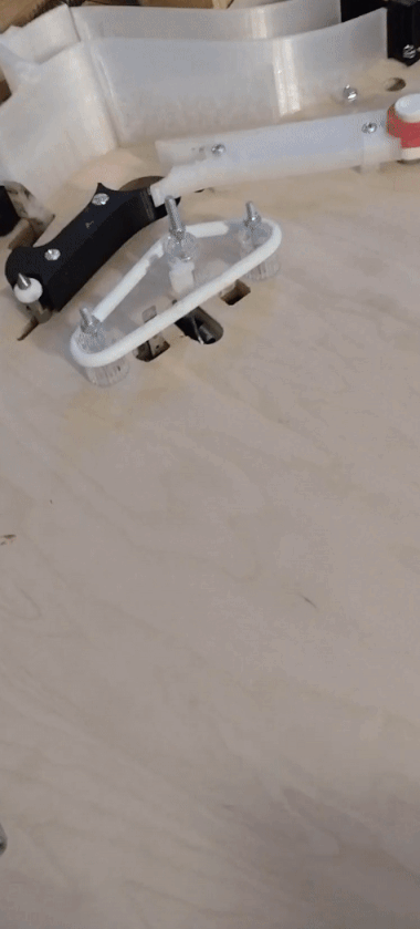
    The VUK is supposed to feed the inlane, so I also make a quick 3D printed part to direct the ball cleanly. I suspect that this part won't hold up long 3D printed, but hopefully it'll at least last a while. I can always try to reinforce it with metal later, or get adventurous and attempt to make a fully metal habitrail for it. But, even if the part breaks every 500 plays, for a homebrew I wouldn't mind just keeping a spare on hand.

    I'm pretty satisfied with this as a proof of concept, so I'll leave more testing and final touches to after I get the playfield assembled, and move on to testing other components

    pasted_image (resized).pngpasted_image (resized).png

    ezgif-2-7ffadd48b0.gifezgif-2-7ffadd48b0.gif

    ezgif-2-2112bef05a.gifezgif-2-2112bef05a.gif

    3 weeks later
    #8 1 year ago

    Started working on the next mech, however in order to test it, I needed a bit more control over the solenoids than I could get by just touching wires together, so I needed to set up a driver board. The driver boards are one of the main parts of Poker which I wanted to revisit. Although they were fairly reliable, I had to have them positioned within about 4" of the MPU for the SPI based communications to work, which meant I had to run about 30 wires all the way through the wiring harness to all the coils, and it was kind of a pain. The boards also weren't that good at driving the coils properly. My CPU that I use is only 3.3V, which isn't enough to 'saturate' the inputs of the MOSFETs I use. They still work, but not as well, which means the FETs heat up quicker, and the coils potentially aren't as strong. That wasn't really an issue for Poker since I ran everything on 25V anyway (and stuff like the flippers didn't go through the driver board) and it didn't really have any high power devices, but this game will run on 50V, and has VUKs,etc, so in the end my driver boards need a complete redesign using new, more powerful FETs and special FET driver chips which can supply up to 18V to the gate, which should work much better. I really like the stern node board approach too, so I'd like the boards to be able to be placed on the playfield near their coils to simplify wiring, which also means I need a new communications system to handle running ~6ft through the noisier playfield wiring, so I designed a new board to test out all that stuff:
    0021_img_20220809_180527411 (resized).jpg0021_img_20220809_180527411 (resized).jpg

    Sadly I made a ton of mistakes. I crossed the ins and the outs on my new RS-485 based communication system, so that was completely untestable, and I put the FETs in backwards in the schematic so the ground and coil hookups were swapped. Plus, I found out the new FET driver chips need a few additional components that I plan for. I was able to work around all that stuff though via some creative re-wiring, and eventually got the board ready.

    To work with the coils, I also needed a source for my 50V. Originally I was going to try a switching supply like many other games are using, but I lucked into a Williams 50V flipper transformer at a show, so I'll just use that. Usually when wiring stuff up, I like to do it in as close to its final form as possible, but in this case, I don't really know where any of this will be going inside the (very small) cabinet, or what sort of shape it'll need, so for now I'm just throwing stuff together0012_img_20220807_154411671 (resized).jpg0012_img_20220807_154411671 (resized).jpg
    And of course, when you wire stuff together temporarily, it always ends up as a horrible mess of alligator clips likely to fail at any moment 0020_img_20220809_180519555 (resized).jpg0020_img_20220809_180519555 (resized).jpg

    1 week later
    #9 1 year ago

    To have a subway, you also need entrances. Usually those are just holes in the playfield, maybe with a deflector plate on top or something. So lets try to make one of those! I start with a scrap piece of metal left over from making the coil bracket before, with a 90 degree bend in the metal brake, and then try to get a good curve on the rest of it by hand: pasted_image (resized).pngpasted_image (resized).png

    Eventually this gets pretty close, but it isn't the prettiest. I needed more spacing on the mounting holes anyway, so this won't be final. I'll have to experiment with a 45 degree plate instead, or maybe find a form to bend them around

    Making a plain subway entrance wouldn't be too hard, I'd just need some 3D printed form to guide the ball into the subway, maybe some metal on the drop area, but I've got a bad idea: combination scoop and subway entrance!
    pasted_image (resized).pngpasted_image (resized).png
    The idea is, make a plunger head for the kicker that's not just a small tip like usual, but instead covers the full inside of the mech, and is angled to feed the ball out the left side into the subway. If I put an 'entry' switch at the top of the hole, I can fire the kicker before the ball actually comes in, and hold it up with PWM, so the ball will just fall into the subway. Or if I don't fire the kicker, the ball will fall down to the bottom, and then can be fired back out like a normal scoop. As a bonus, I set up the dimensions just right so that, if there's already a ball sitting on the kicker in the bottom of the mech and another ball falls in, it'll go into the subway too instead of getting stuck, which means that I won't have to worry about whether I can kick 2-3 balls out at once, and I can probably even use the mech as a 1 ball lock when I don't need the in+out scoop functionality.

    I figured that, unlike the VUKs at the bottom of the playfield to feed the inlanes, since this scoop would be at the back of the playfield, I'd have more vertical room to work with, but it turns out that, since they're mounted *behind* the pivot point of the playfield hinges, I actually have even less room, since that back 6" of the playfield will actually drop down when I lift the playfield up, so again this ends up all being pretty tight, and I need to have the subway entrance be at a weird 38 degree angle compared to the entrance on the top in order to avoid hitting other mechs, but I think it'll all fitpasted_image (resized).pngpasted_image (resized).png

    After getting everything printed, I stick it on my test playfield, and confirm that my design with the second ball exiting while one ball is locked, and the ball smoothly coming down from the top and going into the subway when the kicker is energized, both work as expected. However, when trying to fire balls back out of the top, I run into issues. The ball keeps trying to go out the exit hole on the side, and rattles without making it out the top. I eventually figure out that this is caused by the kicker plate being on an incline, so I need to adjust that enough that a ball resting in the bottom still sits on a flat partpasted_image (resized).pngpasted_image (resized).png

    ezgif-4-ee0375147e.gifezgif-4-ee0375147e.gif

    Now it's all working! Good enough for a proof of concept, so onto the next mech...

    2 weeks later
    #10 1 year ago

    Original cocktail tables all have a 'pedestal' base where they hold the boards, but that makes them hard to sit at. One of my goals is that I can set chairs around this and use it as a dining table, so it needs to have room for people's legs underneath, which means the pedestal has to go
    The original top half and pedestal were just connected via some L brackets and wood screws, so that was easy enough to separate. The bottom side of the cab was made of particleboard, glued and stapled in, but hitting it with a hammer a bit was enough to separate it pretty cleanly:pasted_image (resized).pngpasted_image (resized).pngpasted_image (resized).pngpasted_image (resized).png
    Then I got some new 3/4" plywood (ouch! $$) and cut out a new bottom, minus the big holes, and attached it with a bunch more L brackets, because I hate gluepasted_image (resized).pngpasted_image (resized).pngpasted_image (resized).pngpasted_image (resized).png

    Now I had a solid cabinet, that didn't flex and creak whenever I picked it up, but it still needed legs. Originally I figured I'd just use pinball legs, but there aren't any 90 degree angles in this cabinet! I considered mounting them inside, but I didn't want to have the leg bolts randomly sticking through the sides of the cabinet, and it also turns out that pinball legs aren't a good length if you want to be able to sit at the machine, as you need about 24" of room under the bottom, and the leg bolts are also around that height, so I searched for other options, and found these nice wooden legs for sale at home depot pasted_image (resized).pngpasted_image (resized).png

    Good height, and I can easily just chop off a bit if needed with a saw, and I should be able to install some leg levelers on the bottom by drilling a hole and putting a t-nut on, much like how it works on older machines with wooden legs. But how to attach them? I went back to my handy CAD model of the cabinet and played around some. (CAD is sorta like a disease like that; the more you use it and the more accurate your modeling is, the more you just end up turning back to it for every problem...) I had the bonus design goal here that the legs could be installed entirely from the exterior of the cabinet (no opening the machine, lifting the playfield, and securing them from the inside), so I designed some tight fit holes for the leg to go into.

    pasted_image (resized).pngpasted_image (resized).png

    The grey block can be made out of a few layered sheets of plywood, and then I'll run bolts all the way through to secure everything, and put another piece on top to hold the leg down. At first I was going to just get out a jigsaw and start cutting, but then I remembered.... I have a CNC router!

    Despite building this giant CNC table years ago for the express purpose of cutting playfields, I've never actually used it on wood before, and I was annoyed to find out that my 1/8" bit is only 3/8" long which means.... it can't be used to cut a 1/2" thick playfield! I'll need to locate a longer 1/8" bit in the future somewhere. Luckily I had a 1/4"x5/8" bit for some reason, and nothing about these leg plates needs 1/8" precision, so I just threw it in the router and gave it a shot, with no idea how reasonable my speed and depth settings were, but the router seemed to handle it fine, and the first cut worked with zero issues. pasted_image (resized).pngpasted_image (resized).png

    Test fit.... also good!pasted_image (resized).pngpasted_image (resized).pngpasted_image (resized).pngpasted_image (resized).png

    So I had the router make 19 more. pasted_image (resized).pngpasted_image (resized).png

    This is the real benefit of having a router like this. Usually for one off home projects I never need to make more than one or two of something but here it was perfect, even if it did create an amazing amount of sawdust... I suspect that my vacuum system isn't working properly, though it didn't seem to affect anything as the vortex created by the spinning bit kept the dust away from it. Maybe I need a bigger shop vac, or I'm losing suction somewhere? Or maybe this is normal, it's not like I've ever used one of these elsewhere pasted_image (resized).pngpasted_image (resized).png
    pasted_image (resized).pngpasted_image (resized).png
    Everything worked pretty good, and I was able to install the legs, but they wobbled more than I liked. I saw that this wasn't actually due to the leg wobbling, so much as the entire plywood bottom was flexing since it wasn't really attached near where the legs where, so I added some extra brackets to reenforce things
    pasted_image (resized).pngpasted_image (resized).png

    Now I have a table! pasted_image (resized).pngpasted_image (resized).png

    1 week later
    #11 1 year ago

    My remaining prototyping needs more of a concrete setup to really be tested, so I figured it's time to get a bare playfield ready. Since this is a cocktail, its playfield is slightly wider than 24 inches, which means my usual 2x4 sheets of plywood from the hardware store won't cut it here, so I try to source some larger sheets. Many lumber companies in the city offer 5x5 sheets of baltic birch, which sounds exactly like what I'd want, as it's super strong, has a lot of plys, and due to the exact dimensions of the cocktail playfield, I can actually get 4 separate playfields out of one 5x5 sheet!

    Sadly... baltic birch comes from around the baltic sea, and is apparently mainly a russian product, so due to the war it's out of stock everywhere I look, so I end up settling for a sheet of 4x8 maple, which is a bit softer, but the best thing I can find. 4x8 won't fit in my car, so I ask them to cut it in thirds, since somehow a 4x8 sheet of plywood actually gets me less playfields than 5x5!

    Luckily, I built my CNC table pretty wide, so 1/3 of a 4x8 just barely fits pasted_image (resized).pngpasted_image (resized).png

    My first cut will be pretty minimal, I just want to get the basic outline of the playfield cut, as well as the flippers+slings to test spacing for that so I can get it shooting and tweak the shots from there. Having never CNCed a playfield before, I still have a lot of 'process' to figure out, but my goal is to be able to easily align the playfield in a consistent way, top and bottom, so that I can cut some parts, remove the wood from the table and test fit it, then put it back in the CNC and do more as necessary, so I start by placing 4 alignment and mounting holes around the playfield in non-visible areas, so that I can zero the router to one mounting hole, then jog it to the opposite one and align the wood there, then use the other two diagonals as mounting points to hold the wood down while it's cut. I've got a handy tapered bit that I can stick in the router which should help 'auto center' the hole on the tool to get my realignment as close as possible, so hopefully that will work well once I need to do a few more cuts, but for now I'm just going to do one set.

    My first few cuts go well, and I have some flipper holes and one slingshot cut: pasted_image (resized).pngpasted_image (resized).png

    Then I move on to cutting the borders but on the second time around the edges, something looks wrongpasted_image (resized).pngpasted_image (resized).pngpasted_image (resized).pngpasted_image (resized).png
    When the machine finishes cutting and returns to its home position, it's nearly an inch away from the alignment hole! Somehow during the cut it lost track of its own position, so this playfield is now ruined.

    I do some research and figure out that I was probably cutting too much material for the CNC's speed, and it must not have been able to chew through the wood in that last picture fast enough, causing it to get out of position. I'm not sure why this was an issue this time when it handled the leg mounting plates fine. Maybe the maple was just harder to cut than whatever type of wood I used then? I swap from the 1/4" bit I was using on the leg plates to a 1/8" bit. I was trying to avoid using since I only have one handy that's long enough to cut through the whole playfield, and had trouble finding a source for that one, so I figured that maybe that sort of thing was out of spec and I should avoid stressing the bit in case it breaks, but I have no idea if that's true or not. The 1/8" bit does have the advantage that, since it's small enough to cut rollover slots and holes for t-nuts, I don't need to swap tools as much, so hopefully it'll work fine.

    I regenerate my files with the 1/8" bit in mind, drop my cutting speed by 50%, install my second sheet of plywood, and cross my fingerspasted_image (resized).pngpasted_image (resized).png

    Looking good! One of the troubles with using the CNC router to make accurate cuts is that it's the most accurate tool I have, so it's hard for me to verify if it actually did a good job, but some quick tests of things like the diagonals confirm the cut is at least 'square' and has the right overall dimensions, so the rest should be good... right?

    I throw the mounting hinges on and do a quick test fit pasted_image (resized).pngpasted_image (resized).png

    It fits in the cabinet! That's a good sign. Or so I think, until I try to lift the playfield, and the back edge hits the bottom floor of the cabinet.... At some point during the designing, I figured I could gain a bit more room by extending the edges of the playfield from the original measurements of the Roy Clark playfield as there was a lot of air space around the edges, and part of that was adding 3/4" to the top edge of the playfield. My CAD showed that the edge shouldn't hit the back wall behind it, and it was right on the money. Too bad I didn't test raising the playfield in CAD too after making that change

    There's no real way around this issue, so I take 1/2" back off the length of the playfield and rearrange everything to fit, and then manually cut that off the playfield to keep it matched up. Better than having my cut be too small I guess

    2 months later
    #13 1 year ago

    Been making progress on a lot of things in parallel, but nothing quite ready enough to post yet

    Originally I'd planned to cut the playfield bit by bit, starting with just the bottom to mount the flippers+slings as shown in the last post. Verify those work, test some shots, then finalize more of the CAD and do some more cuts, repeat. My motivation was to try and the playfield 'good' on the first board. But as I started installing those basic things, I realized just how much work it'd be to strip all of it off again to put it back in the CNC for updates. Considering that, no matter what, I'll have to do a full pf tear down+rebuild at least once when I get to the point of putting in all the holes for inserts, etc, I'm thinking that it's really not worth it to be concerned with getting this first wood 'good' and 'clean'. One blank is only like $30-40. I might as well plan to just use at least one more blank for the 'final' pass with inserts/etc and consider this first piece to be scrap that I can mess up as much as needed, and with that in mind, I might as well just cut the entire playfield in one go, to save time+effort over repeated smaller cuts. Some stuff will surely be wrong, and I'll need to manually fix it or maybe do another pass on part of the wood and have a bunch of wrong leftover holes, but that's fine.

    So rather than focusing on getting the first mechs installed+flipping, I instead focused on getting the CAD complete enough that I can do a full playfield cut, and I think I'm pretty much there. I've tried to be intelligent about what parts need to be figured out now for proper hole placement, verifying everything fits, etc, and what can still wait, but that still means a lot needs to be done.

    One of the main things that was left to get the CAD looking 'good enough' was to plan out all the ball guides for the shots. Originally I was planning on 3D printing all of these for simplicity, but once I got started modeling those it turned out that some places would need to be metal due to not having room for the thickness needed to make a strong enough plastic part, or being a very high impact area, etc.

    On my last build, I roughly drew these metal guides in 2D, then measured their length, and asked a local metal shop to cut me some strips, then I manually fabricated some mounts, bent everything, etc. This worked okay, but wasn't very precise. Everything looked a bit ugly if you stared too close, and when trying to go from that to making art, etc trying to match my hand bent curves was one of my biggest pain points, so I decided to go a different route, and get everything laser cut online on sendcutsend.com. I also discovered that they support bending sheet metal (although sadly, only hard bends, no curves), and that sounded very convenient for the price compared to making all the mounting brackets myself, so I ended up designing all the bent sheet metal in CAD, which I'd never done before. A bit of a learning curve, but I eventually figured out a good process, and made some designs that felt very 'professional' looking:
    pasted_image (resized).pngpasted_image (resized).pngpasted_image (resized).pngpasted_image (resized).png

    In the end each of these was around $8-12, not too bad. pasted_image (resized).pngpasted_image (resized).png

    I'm not sure how well bending the curves in will go after all this, and I might have gotten the metal a bit too thin (I used 0.030" stainless), so we'll see how it goes once I bite the bullet and cut the playfield so i have mounting holes to bend to

    #15 1 year ago
    Quoted from TreyBo69:

    What tool(s) do you use for bending your rails?

    In the past, for sharp bends, I'd either use a HF metal brake or just stick it in a vice. Was never satisfied with the results though, and you could never rely on it to be too exact. these SCS bends are nice and clean, and I can request specific angles too.

    For curves, what I did last time was to basically clamp a piece of plywood to the top of a table, some small spacers between it, so I had a deep slot to stick the metal into, and then I'd just press down on the end sticking out by hand, while pulling the metal out slowly, so I got a curve. As long as I got the basic shape of the curve close enough on the first try I could usually adjust the 'degree' of the whole curve later by just bending it in the air, or do slight changes to the shape by pressing both ends down on a board sticking out of my vice. Hopefully that'll work here too, although having the 'feet' already bent will probably get in the way a bit. I'll try to grab some pics when I get there

    #19 1 year ago
    Quoted from BorgDog:

    0.30" sounds really really thick!

    That's because it's actually 0.030"! lol.

    My problem with using random round things as forms is that you never get that actual radius, the metal always seems to bend back a bit. If I was trying to make 5+ of the same radius bend, sure, I'd look around for something that ended up at that radius. But in this case I've got like, 50+ bends, all at arbitrary radiuses.

    Quoted from TreyBo69:

    Yeah I thought of tackling it like that, but also thought about maybe buying a roller for more consistency and smoother bends
    Something like this
    [quoted image]
    Set the rollers to the desired rate of curvature, feed flat metal in and roll it through with the lever

    This could work really good, maybe? I've never seen one before, and hard to justify buying one if you don't know how to use it / how well it'll work

    #24 1 year ago

    Decided to try bending one of the guides just to see what I'd be dealing with, turns out the 0.03" stainless bends pretty easily by hand. For the tips I had to stick it in a vice to get some leverage. Nice for fabrication, but maybe not so nice when a ball is running into it. Time will tell, but I could picture these starting to bend a bit from repeated impacts. pasted_image (resized).pngpasted_image (resized).png

    At worst I can always order them from something thicker, but in many cases that probably won't be needed, since I'll also have some plastic guides for more complex shapes/low impact areas. Originally I considered making more of the guides from plastic (either 3d printed or laser cut) but I figured that might not feel as good to shoot.

    So I printed one of these guides out, and used it to get the metal guide bent more precisely into shape (handy to have built in forms!). pasted_image (resized).pngpasted_image (resized).png

    I think that should handle all my main guides in the layout, and provide the extra rigidity needed to keep the thin metal from bending, so at worst I'll just have to design more of these plastic guides to back the remaining metal ones.

    I'm also going to start experimenting with a few different filaments and inflow settings to see if I can get the plastic to light up well with some RGB GI lighting...

    pasted_image (resized).pngpasted_image (resized).png
    This is transparent PLA with 10% gyroid infill and a random red LED I had, which is probably dimmer than the NeoPixels I'll be using. It looks a bit better in person and diffuses well, but you can see the gyroid pattern pretty clearly and I doubt it'll provide any actual illumination outside of the plastic. That may be okay though, I want to be able to do cool GI light shows as much as I want to light the playfield. That can always be done with a strip under the apron or something at worst (as long as I can find an angle where it doesn't reflect off the playfield and blind people walking by, since unlike a normal pinball machine this table is open on all sides)

    #27 1 year ago
    Quoted from Cmartin1235:

    Another way to minimize the infill geometry artifact is to print your plastics upside down with approximately four perimeters, and no volume other than the perimeter itself. If you get your model, right, it’s like an injection molded piece that you then flip over and attach to the playfield.

    I do print them upside down. I think I want the dispersion elements of the infill though, hollow would probably look different. Another option might be to cover the 3d printed parts with a layer of frosted sheet plastic...

    #29 1 year ago
    Quoted from Aurich:

    I've actually long wondered why we haven't seen more 'mini' pinball homebrews. So many advantages if you're willing to tackle a little something different. Already love your out of the box thinking for the engineering.

    Only other one I can think of off the top of my head is what Ben Heck did, and that wasn't a super serious project.

    I know there's stuff like the Frozen homebrew, which is a widebody in a shortened cab, probably similar playfield dimensions to a cocktail, although it's still a full size pinball cabinet. Also Trashland, which I'm pretty sure is wider than it is long, but again, full cabinet. I think there's also one or two in the works that are based off the stewie-pinball flippers/scale?

    #32 1 year ago
    Quoted from Aurich:

    Obviously everyone should make whatever the heck they want, but it would be interesting to see more genuinely 'small' projects. if you're in a full cabinet you need the space for a full game.
    Just wonder if there's an interesting way to make "apartment friendly" pinball.

    I'm hopeful that at some level that's what this project will be. Just a more convenient form factor in general. Can be used as a normal table for eating at/etc. Easier to pack up+store, move without needing two strong guys and worrying about stairs+corners... One of my stretch goals is to even fit some small wheels in the bottom somewhere so you can roll it around without a dolly

    Even with no head, Poker is still a pain to transport, which feels a bit of a shame for a homebrew you'd like to bring around to places and show

    #36 1 year ago

    I still haven't ever streamed the final version of poker with the art and stuff.... Some day

    #38 1 year ago
    Quoted from Gornkleschnitzer:

    0.03" is probably fine. That was the size I ordered when I built Undertale. It's not quite as solid as the 0.048" that I used for VB, but I suppose the easier bending is an advantage.
    Just watch for unsupported ends, which will spring back a surprising amount when hit by a ball. The art scratched off this plastic is how far the Hotland passage wall bounced inwards from random ball hits. About 1/4 inch. However, it did still keep its shape; if it wasn't tight enough to damage the plastic, it would have been all right.
    [quoted image]

    All my guides are elevated 1/4" from the playfield so I don't need to worry about that as much...

    Idk what they used on my ACNC, but it seemed similar and has bent over time

    1 week later
    #39 1 year ago

    Got the power wiring in the cabinet all set uppasted_image (resized).pngpasted_image (resized).png
    At the top you can see the 3.3V, 5V, and 12V power supplies, and a power outlet for the Raspberry Pi's USB adapter. I would have preferred to use a single ATX power supply to get the voltages, but there weren't any easily available ones to fit in the short space available, while these individual supplies were cheap and available from digikey. The Pi could be powered off the 5V supply, but I ran into issues on the last build with noise from that technique, and this will allow me to keep the Pi powered while the rest of the machine is off for fast 'boot'.

    On the bottom you can see a small Williams transformer which was used on many system 7-9 games to provide 50V for the upgraded flippers while still using their old, larger, multiple voltage transformer for the rest of the game. It fits nicely under the shooter rod area of the apron, and will hopefully be able to provide enough amps to power all the coils on the playfield instead of just the flippers. The wiring for this is in a big messy bundle right now since I decided not to go cutting up the original harness unless I needed to.

    pasted_image (resized).pngpasted_image (resized).png
    Even outside the 3 different DC voltages needed, I have a lot of different power 'rails' that I wanted to individually fuse. In many cases, I also don't know what voltage will actually be needed for things either (for instance, my inputs could be powered by 3V or 5V), so I set up this area to allow me to easily change what power supply is hooked to what rail(s). Right now there's just two fuses but eventually I think I'll end up with 6-7, each running two one of the three sets of orange connectors for the different voltages.
    pasted_image (resized).pngpasted_image (resized).png
    Five different power supplies means a lot of wiring, so I tried out some 'Wago' connectors to avoid having to spend time hunched over soldering everything. I found a handy 3d print on thingiverse for clamps to mount them. Sadly the connectors I got from eBay turned out to be knockoffs, not real Wagos, so they didn't fit and I had to spend a sunday afternoon tinkering with the prints to fix it

    pasted_image (resized).pngpasted_image (resized).png
    Wiring also means wire colors! I planned out all the power wiring in advance in a spreadsheet (since I've never found a good software for drawing this type of schematics), and also made a big list of my switches and coils too so I could start assigning colors to them once I reach that point. I was planning to get some fancy pre-striped wire from https://wirebot.xyz/ this time, but after listing everything out I realized I had more switches than there were possible color code combinations, and I'd need to go to a two-stripe system anyway, so I busted out my old wire striping solution, a 2x4 with two very precision placed holes, and an oil based sharpie marker stuck in top

    #40 1 year ago

    One pain point I keep running into on builds is all the switches. Every layout looks nice and clean until I remember I need to stick a bunch of them in. Rollover switches require cutting slots, which is hard to do (at least by hand), and have lots of alignment issues. Plus they can mess with slow moving balls. Rollunders avoid many of those problems, but are ugly and require visible wiring on the playfield On Poker I thought that star rollovers would be the answer. Easier to cut the hole (since it takes a regular circular bit), works in any direction, cheap. But once I moved to using a playfield protector that was all ruined. I tried using eddy sensors and they worked quite well, but the only ones I can source are large and expensive.

    Eddy sensors are still my backup this time, but I'm placing my bets on reflective optos. After a lot of searching I found a sensor that looked promising, and ordered some of these little boards from JLC PCB. Each one has a NeoPixel RGB LED and an IR distance sensor, squashed together just enough so that they can fit inside a 5/8" insert
    pasted_image (resized).pngpasted_image (resized).png

    Depending on how close the object is, I can get a reading from 0.1V (touching) to 3V (about 3" away). I'd hoped to be able to hook this directly up to my input chips, since they have a active voltage of <0.7V which aligns with my readings from the sensor (0.3-0.5V with a ball directly in front of it), but once I put an insert on top that stopped working. I played around a bunch with the values of stuff and after some calculations, was able to find a set of resistors that'd give me 1V with a ball partly over the insert and 1.4V with no ball. (0.25V with the ball directly over, but that's not as useful) Only 0.4V isn't a lot to work with, but I calibrated a voltage comparator chip I had on hand (LM339, same that's used in WPC opto boards) to a 1.1V threshold and it seems to work pretty good on the bench. ezgif-2-4ecfc54e92.gifezgif-2-4ecfc54e92.gif

    More testing will need to be done once I've got the RGB hooked up to see if that messes with it, or if lights above the playfield/machine, but I think it's a decent direction to go in. If necessary I can try to make custom clear inserts out of PETG or something to reduce the interference, etc

    #45 1 year ago
    Quoted from BorgDog:

    interesting. how does it do at speed?

    I feel like that's an issue for the board the switches are hooked up to, not the switch type? As long as it generates a pulse at all...

    Quoted from TreyBo69:

    Neat. Reminds me of the switches JJP introduced on GNR in a few spots. Same sorta sensor that detects when you put your phone up to your face and turns the screen off

    I originally looked at using the same component they use (which is literally designed for cell phones). Their sensor is much more advanced, and even has built in ambient light detection, etc, but uses a completely different interface that'd require a dedicated cpu instead of just hooking it to a regular switch input like these

    #47 1 year ago

    With good power, I should have everything I need to get flipping, right?

    I built up a test board but.. discovered some issues pasted_image (resized).pngpasted_image (resized).png

    Some traces cut and wires jumpered was enough to get basic testing down, but the fixes would involve remapping most of my pins, so I ordered another set of PCBs with the fixes and populated enough parts for some flips pasted_image (resized).pngpasted_image (resized).png

    Here's a quick test with just the power winding hooked up to a 40ms pulse:ezgif-5-7726218447.gifezgif-5-7726218447.gif

    Next I actually installed the cab switch and ran all the wiring. A few problems came up that needed some tweaking pasted_image (resized).pngpasted_image (resized).png

    Time for the first real test flip!ezgif-5-9b801f73c4.gifezgif-5-9b801f73c4.gif

    Still some issues to work out with my input code (flipper sometimes comes down too early, or does another flip as I release, etc) but nothing too complicated

    #51 1 year ago
    Quoted from Gornkleschnitzer:

    I love your lane switch design, especially considering its similarity to something I thought of but never prototyped. My idea would have been an eddy sensor version but still with the built-in light.

    I'd love to use an eddy sensor too if I could find one small enough to fit in the same profile. I found one cool looking chip that could actually use a small coil drawn on the pcb to do detection but it's been out of stock forever and there's no other comparable chips which gives me pause

    #53 1 year ago
    Quoted from Gornkleschnitzer:

    I was briefly browsing the Mouser catalog to see if I could find anything of value, but didn't end up seeing much on that or how to actually design an eddy sensor circuit. It seemed like there are quite a few supporting components needed, which gave me some pause. I do wonder if it would be feasible to build a more focused sensor from scratch (along the same lines as the trough sensor in TZ) with some magnet wire and a 3D printed spool. Maybe throw on an ATTiny and have it watch an analog input.

    https://www.mouser.com/ProductDetail/Texas-Instruments/LDC0851HDSGR?qs=diC8vqfyxkrjshhE0MppEQ%3D%3D#
    This is what I was looking at. They have a section talking about the PCB design, looks like minimal additional parts:
    pasted_image (resized).pngpasted_image (resized).png

    I feel like at the point I'm adding a dedicated CPU to a single switch I've gotten too complex. Similarly I could probably make my opto sensors work better with an added microprocessor to filter out ambient light, etc but that's something I want to avoid if at all possible

    #54 1 year ago

    Getting near to cutting the first full playfield, so did some test cuts to verify stuff fits. No big issues found, although my target holes were a bit tighter than expected, and the inserts were all a bit loose, especially stuff where I relied on existing models on the internet vs measuring my specific parts myself.
    pasted_image (resized).pngpasted_image (resized).png
    One big thing I learned though that I'll need to remember in the future is to be aware when positioning parts in the CAD sketches of what part of the shapes I'm dimensioning to. For instance, I needed to make the thickness of the holes for my narrow standup targets 0,1" bigger to allow the full bracket behind them to fit in. But often they were positioned by dimensioning them to something behind them, so that ended up moving the whole target forwards instead of just adding some room in back. Meanwhile when I mounted the target models to the holes in my 3d assembly, I mounted them all relative to the back for convenience, so when I made every target hole thicker, it moved all my models back, and that had to be corrected to so I could check the fit properly. Or when I placed multiple targets next to each other, I dimensioned between their adjacent edges instead of from their centers, so if I needed to make the holes slightly wider (which shouldn't affect the spacing), it'd throw everything off. I need to keep a better awareness of what part of each component is actually important to the play/its positioning, and always reference that instead of whatever is handy at the moment... pasted_image (resized).pngpasted_image (resized).pngpasted_image (resized).pngpasted_image (resized).png

    In general I've also learned I need to break up my playfield sketches a bit more... When I made the hole for my drop target 0.025" wider, that compounded into a scoop 8" away moving 0.25"! Looking at the subtle changes, none of them were 'wrong' and during the design phase I might not even notice them, but now that some things like guides have already been manufactured, their dimensions and mounting points are sorta 'locked in'. For a real manufacturer that wouldn't really matter and they'd probably just remake all the parts for the next prototype build, but for a one off trying to conserve money I need to be aware of any time stuff like that happens.

    From what I've seen of other homebrewer's CAD designs, none of them use nearly as much constraints/dimensions as I do, and it's often more of an enhanced drawing than fully defined CAD work. I'd love to get ahold of a file from some of the professionals to compare, although I bet there's a lot of variance between different designers there too

    #55 1 year ago

    One other big problem I'm going to need to nail down before cutting the playfield is the trough. None of the allied leisure games have multiball, but I'm going to need a multiball trough, and it needs to be able to handle more balls than usual since some will also get staged in the subway. The games originally had a pretty standard trough, just a rail going from the outhole to the shooter lane, with a kicker in the outhole. The only difference from normal one ball troughs is that it was much longer since this is a widebody. So I planned to use this mech, and add a second coil to control a gate on the other end to release balls one at a time into the shooter lane. Not a complex thing, there's a lot of space to work the mech in, so I'd think about the details later.

    pasted_image (resized).pngpasted_image (resized).png

    As I started to do more of the layout, I found that there really wasn't much room on the playfield for the type of layout I wanted to do since it's a shortened cocktail size. So I moved the flippers/inlanes/etc down half an inch to make room for something, and then forgot about it. Then I did some more layout, and realized I'd mis-measured the playfield. I was putting stuff about an inch too far up the playfield, considering how close it gets to the glass, and would need to move stuff down. So I rearranged stuff, and when that didn't solve the issue, slid everything down another 1/2". And then forgot about it. Eventually I had the layout all finalized how I liked, and then realized there was no room for the trough!pasted_image (resized).pngpasted_image (resized).png

    With the inlanes moved down, there was now no straight line from the outhole to the shooter lane at all. I assumed a modern style trough would work here, since they go under the playfield (allowing me to route the right outlane over it), but it didn't really fit that well since this is a widebody. The distance the ball needs to travel from the outhole both to the right and up the playfield is just much larger than what a standard sized game needs. I might have been able to work around that with some creativity, but then I realized, with the trough being at the very bottom of the playfield, and the cabinet being shallow to begin with, the trough would hit the floor! On top of all that, the area under the apron parts of the playfield turned out to be prime real-estate for other stuff, like the transformer, so really it'd be best if the entire trough could somehow fit above the playfield. I played around with a few ideas of how to fit it in, but in the end this concept was the only one that had potential: pasted_image (resized).pngpasted_image (resized).png

    Now to make that into something workable...
    pasted_image (resized).pngpasted_image (resized).png
    I worked some mounts for optos directly into the 3d printed walls, so it should be able to detect up to 4 balls, plus one 'jam' opto if two balls get into the kicker lane. Unlike regular troughs it also has a one way gate at the end to prevent balls from falling back in. Since I needed it all to be above the playfield, the coil is mounted to that orange metal base plate above the balls (I didn't bother modeling the coil itself).
    pasted_image (resized).pngpasted_image (resized).png
    The kicker is designed a bit differently from the plungers normal troughs use, and instead is the full width of the lane. My idea for that is that, when kicking a ball, instead of just immediately releasing the plunger again, I can hold it up with a PWM current, preventing the balls remaining in the trough from entering the lane. Then, if for some reason the ball that was kicked to the shooter lane fails to make it, it'll come back down and rest on the extended plunger, triggering the trough jam opto. Then the plunger can release, and hopefully the ball will fall back with it, preventing the other balls from rolling in, and it can try again fresh. We'll see how well that works once it's built though...

    pasted_image (resized).pngpasted_image (resized).png
    I printed out the guides, mostly just to test that they aligned with the dimples in the playfield (my first time doing something of this precision with this many separate parts, all made by different processes), but there were no issues. Running a ball through by hand, it also seems that the angle of the wall where the ball ejects into the shooter lane is enough that the one way gate might not even be needed. I'd assumed it'd bounce back and forth vertically and then trickle to the shooter lane from the angle of the gate, but even without the gate the ball is never touching the plastic a second time

    Everything seemed solid there so I left the matter of constructing the kicker mech until I had the electronics set up enough to do a real test. That is, until I reinstalled the shooter rod, and noticed this:pasted_image (resized).pngpasted_image (resized).png

    Slight misalignment! Turns out that when you put a 6.5 degree playfield in a 3.5 degree cabinet, things don't line up! I'm not sure how I overlooked that for so long. I'd carefully measured the shooter rod positioning and modelled it in CAD so that I could line up the shooter lane....horizontally. But never looked at the vertical alignment. I guess I just figured that there was some vertical play and that'd be enough, but obviously it's not. The angle is also wrong, but I think the plunge would still work okay if the plunger was angled a bit downwards compared to the playfield.

    So how to solve this? The cabinet really isn't built in a way where I can just cut another hole or anything. I thought about some weird 3d printed thing that'd clamp onto the shooter rod and suspend another one an inch lower, but I doubt that'd work well. We'll just have to raise the playfield to match! pasted_image (resized).pngpasted_image (resized).png

    I designed a 3D printed reverse ramp to sit in the shooter lane and ease the ball from the height+angle needed for the shooter rod at one end to meet the playfield at the other. This also has the added benefit of handling the shooter lane groove, so now I don't need to deal with carving that from the wood. Now the trough just needs to get the ball up to the shooter lane, so those 3d printed guide walls will need to become a 3d printed ramppasted_image (resized).pngpasted_image (resized).png
    Now that there's an extra ramp to make it up, I can't trust my hand testing as much, so it's also time to finish the mechanism and get a coil in therepasted_image (resized).pngpasted_image (resized).png
    pasted_image (resized).pngpasted_image (resized).png
    Some more sheet steel bend on the metal brake make a coil bracket, and for once I got my holes drilled close enough that it went together on my first attempt. It's only now that I'm realizing I could have just had these coil brackets precision cut+bent at sendcutsend along with my ball guides, but oh well. The plunger is just a handy 7/16" bolt I had around. My original design called for another 1/4" bolt run through a hole in that down to the 3d printed kicker head, but I think I might not need that extra strength, so I made the full head out of plastic and just hung it on the bolt.

    Sadly... it doesn't work. The ball barely gets 1/4 of the way up the ramp, and it seems super weak, enough that I don't think it's just a badly designed mech causing issues. Turns out this is the fist instance of me seeing something I'd always wondered about: how much does having the full plunger be metal matter?. When you look at VUK plungers, etc, you'll see that the upper half is always made of rubber/plastic, while the lower half is metal, because if the upper half is also metal, the coil will be trying to pull some of that backwards. I knew that using an all metal plunger would make stuff weaker, but I didn't think it'd be so noticeable!
    pasted_image (resized).pngpasted_image (resized).png
    Back to a two part plunger then. I've needed to make a lot of these over the years but I've never come up with a satisfying way to do it given my machining abilities. In the past I had a friend good with a lathe machine a thread onto the end of the metal part, and then machine another plunger with a threaded hole out of aluminum (non-magnetic), which worked amazing, but they moved to Florida... Then I used a part i found on marco, a williams drop target plunger. It has an integrated thread on the end. And then I 3d printed another end and manually tightened it onto that thread. pasted_image (resized).pngpasted_image (resized).png

    Works well, but each plunger is $6, and they usually need additional modification on the other end to mount stuff to them, vs a $1 bolt I can get at the hardware store.
    So I decided to try my hand at a new approach, and thread a hole in the plunger to attach a 3D printed plastic end to: pasted_image (resized).pngpasted_image (resized).png
    This works, but isn't the best. I can't cut a bolt at an exact 90 degree angle or get the surface flat afterwards, and where I drill might not be exactly centered either. The screw (and thus, the plastic plunger) ends up slightly angled and off center. In this case, that's fine. I just make the plastic plunger a small enough diameter that it won't scrape the sleeve. Still on the lookout for a better solution though.

    With a 2 part plunger, the kicker is nice and strong, and I can finally test it with a fully loaded troughezgif-4-6da2301fd4.gifezgif-4-6da2301fd4.gif

    I think that's good enough for now. Once I have the optos hooked up, etc and some code controlling it I can get more detailed.

    Two concerns going forward:
    - The angle of the trough isn't too high, so the balls roll down it quite slowly, especially when there's only one left. Hopefully they don't start getting stuck. I can't really angle stuff much more in the space I have though
    - I'm not sure what the optimal length to cut the plunger into its two pieces is. I'm sure some physicics/math professor could give me a proper answer, taking into account the range of motion of the plunger and the length of the coil. Right now I've guestimated that the metal plunger should stick into the coil around 0.7" by looking at some random other mechs I had from actual machines. But I bet that 0.1" either way could have a noticeable effect in a situation like flippers or vuks where you need every ounce of power you can get

    #56 1 year ago

    A curved shooter lane needs a curved side rail! (and I need side rails if I ever want to assemble this thing...)pasted_image (resized).pngpasted_image (resized).pngpasted_image (resized).pngpasted_image (resized).png
    It also need a few other precision cuts, so I realized this would be another good use for the CNC router! usually for siderails I needed to find 0.5x1.5" wood and then cut it down to 1.25" by hand, which means finding someone with a table saw, so realizing I could do all these on the router was convenient.

    My first rail didn't go so well though. Unlike the playfield, there's no holes in the center of the part to mount it to for cutting, and I wanted to use the 'natural' edge on at least one side too since I didn't know how the CNCed edge would look after, so I tried to clamp it down from the sides with screws, but the vibration worked them free and the cuts got a bit messed up
    pasted_image (resized).pngpasted_image (resized).pngpasted_image (resized).pngpasted_image (resized).png
    Still usable, so I figured it was good enough for the first whitewood at least. For the other two I gave in and drilled some placement holes in locations that shouldn't be visible when assembledpasted_image (resized).pngpasted_image (resized).png
    As you can see in that one pocket though... I placed the hole wrong, and ended up going back to the side screws mid-cut in order to get it to work, so the second rail was also a bit messed up
    With some post processing though I got them workable, but definitely not as clean as I'd like pasted_image (resized).pngpasted_image (resized).png
    In the end though, three rails ready to get drilled and mounted!

    pasted_image (resized).pngpasted_image (resized).png
    #61 1 year ago
    Quoted from Aurich:

    Fascinating project and obstacles, but I can't help but ask the obvious: with all the work, constant struggles, and limitations—not to mention the access to the tools you have—why not simply design your own cocktail cabinet? Make a few tweaks to allow for the design you want, and then if you ever want to make another one you don't have to hunt for another donor.
    It's fun to see you problem solve either way.

    You've seen all the challenges I'm having just cutting single pieces of wood... Imagine if I had to join two together. At 45 degree angles! I'd like to get there eventually but that seems like a bigger hurdle than all these (individually) smaller things. I don't think a custom cabinet would solve all the problems either. If anything, I wish the cab was even shallower (from the perspective of how it'll be once it's done), but I just don't think that's reasonable at this point, at least not without simplifying the layout a ton (I just like tall mechs too much).

    That said, I want my next build after this to be a custom cab, and did consider it here, but I also had issues like dealing with the glass, molding, etc. For regular cabinets I can get that stuff but for a cocktail I'd need to fabricate it all too, which would be another layer of work beyond even the cabinet construction.

    Pinball construction is an interdisciplinary endeavor, and I could add more things requiring more new skills ad infinum, but even some of the skills I've already picked up for it aren't things I'm interested in (like operating a cnc router!) but for whatever reason the calculus usually ends up with me learning + doing it, begrudgingly, instead of the other options, so when I see an opportunity like this existing cab, I see a long list of work, failures, and learning that I can avoid entirely

    Quoted from Cmartin1235:

    Actually, I think the rails look pretty good. On my CNC I always cut my parts from larger stock with holding tabs. I screw or clamp the edges of the waste and then don’t worry about it coming loose. It’s wasteful of wood, I know. But it works for me.
    Have you looked into a boot and dust collection system? The only drawback is static electricity which can zap your controller or worst yet ignite the dust. So you have to ground it!

    Usually I would too, but I wanted to use the original edge on the top side. Turns out that after sanding, the cut side looks just fine anyway, so that was a waste of effort.
    Holding tabs would have been a great idea too.... if I'd remembered they exist! Noticed that button staring at my in my CAM software about five minutes after

    I actually do have a vacuum hose hooked up, etc, but it doesn't work too well. I usually need something to do anyway while waiting for the cuts so I'll just use the vacuum by hand to clean up after it fe time to time. Works good enough considering that it doesn't tend to pile up thick enough to cause issues anyway, so I haven't investigated improving the vacuum/boot. Plus I don't have a z stop so any larger boot would make it even harder to see what I'm doing while calibrating everything

    Quoted from TreyBo69:

    If you don't set yourself a few arbitrary design limits, where's the fun in coming up with creative solutions?

    Yeah, but, don't forget all the creative new ideas I had to shelf because I couldn't work around the limits too! Often I think I'd take that trade

    #65 1 year ago

    Time to cut the playfield! pasted_image (resized).pngpasted_image (resized).png

    I needed to take off the back bit, since the playfield hit the bottom when I tried to tip it up pasted_image (resized).pngpasted_image (resized).png
    This required doing a full cut around the edge of the playfield since I hadn't figured out how to just do a line in my CAM software yet, but it was very gratifying watching the router trace the entire edge without taking off any wood at all. Looks like my alignment holes are working!

    The full process took over two hours Luckily I had a machine set up next to the CNC table to play while I monitored it

    Things went pretty well overall, just a few small issues:

    - the top edges of the holes are a bit messy. I think a quick sanding should fix this, but I bet it can be improved
    - when I did the dimples on the bottom, I told it to do a circle cut, instead of a drill, so my dimples are now like 0.15" wide... pasted_image (resized).pngpasted_image (resized).png
    - when I went to cut some recesses on the bottom, I forgot to make it carve out the centers (usually it just does the edges of holes and leaves a floating piece of garbage pasted_image (resized).pngpasted_image (resized).png
    - once I fixed that and re-ran it, one of them encountered a knot filling hidden in one of the inner plys, so that area of the playfield is now really thin, right where an insert will be going eventually pasted_image (resized).pngpasted_image (resized).png
    - the little bit of wood on the right side of the shooter lane had already been fragile, and the plys had started to separate a bit. When the router got to it the whole thing shattered. not a big deal though, the side rail will go above that anyway. I could probably just cut that whole strip off... pasted_image (resized).pngpasted_image (resized).png

    Now to test fit everything
    pasted_image (resized).pngpasted_image (resized).png

    #67 1 year ago
    Quoted from MrBigg:

    Anytime you encounter knots, thin, or empty cavities, a CA bath on that area works great to rigid things up. When I use worm wood, or spa.ted(rotten basically) woods for guitar tops, I always CA (thin super glue) bathe the whole top before gluing it to the guitar body. I do the same on my playfield if I encounter that issue, and it's usually rock solid in a very short time. Just a thought. Looking really good so far

    Yeah I probably could have done something about it if I knew it was there. First time it was visible was as the router cut through the layer above and bit into it

    1 week later
    #68 1 year ago

    Time for some test fitting! pasted_image (resized).pngpasted_image (resized).png

    I prep each mech with new parts, coil sleeves, etc, along with color coded wires and connectors. On Poker, I only did connectors on the drop target banks, thinking that I'd rather have less potential failure points compared with how often I'd need to take any other mechs off.... and that did not pay off. So, connectors for everything!
    pasted_image (resized).pngpasted_image (resized).png
    For the pops, I'm stealing some all in one plastic mechs from the parts cocktail. They're actually really nice, so hopefully they work out. I can always fall back to some ballys or data east if they cause issues. New flipper mechs from PBL. I have some old williams mechs I could use but after the cost of rebuilding them it's not worth it...
    pasted_image (resized).pngpasted_image (resized).png

    In some places I had to use bally linear slingshot mechs instead of normal hinged ones due to fit, and that also leads to my first fit issue:pasted_image (resized).pngpasted_image (resized).png
    I widened the switch slots on this slingshot since I wasn't sure where I'd want to place them... not taking this mounting point into account. It looks like there's wood there but the edge is so close that if I put a screw in it'll burst out the side.

    pasted_image (resized).pngpasted_image (resized).png

    For the lower bank of drops, the only style mech I could find that was short enough to fit was a williams style. However, I didn't have any of those! Turns out the mech from Alien is a complete rip off of the williams design though, and I did have a spare of that! The targets are a direct match, so I've got some PBL transparent targets on order, and I'll try to rig up RGB lighting for them
    pasted_image (resized).pngpasted_image (resized).png

    The upper bank uses a six bank with memory from a Bally Kings of Steel with some handy new targets I found in a bargain bin at the York flea market for $2 each

    pasted_image (resized).pngpasted_image (resized).png
    A magnet stolen from a parted out Addams Family barely fits under the upper drop target bank, but my CAD modeling was correct here, no issues.

    pasted_image (resized).pngpasted_image (resized).png

    The parts playfield also had some Allied Leisure single drop target mechs. These have a cool benefit over other mechs like the commonly used williams ones in that they're completely self contained horizontally, so you can stuff them next to each other in tight spaces. On the other hand, no memory/knock down coil, so that's something I'll need to be wary of in my coding. While I thought I had a bunch of these, once I pulled them off the parts playfield, I discovered most of them were broken! Luckily I'd already designed a 3D printed version for my Star Shooter when one was missing, so I printed up some more and fixed them up. I used black here but I've got some transparent filament on the way, so hopefully I can find a way to make these lighted. The plungers stick down really far for some reason, about an inch out even when the target is up, and drag on the floor of the cabinet when I tip the playfield up, but it just pushes the targets up and doesn't get stuck, so that's fine.

    pasted_image (resized).pngpasted_image (resized).png
    What isn't fine is my power supplies! I'm going to have to relocate at least 3 components because some of the mechs hit them, despite my careful planning before hand. I've started trying to trace each mech's footprint on the bottom to avoid future issues, but it's not very precise since I can only get in there to draw with the playfield up. Hopefully I don't need to redo too much of the wiring...

    pasted_image (resized).pngpasted_image (resized).png

    Cabinet issues aside, all the mechs so far have gone in without issue. The one thing remaining is the vuks/scoops/subway, but I don't have that completely designed yet, and since it's completely custom I can always design the mechs to fit the available space, so I'm not as concerned as I would be for off the shelf stuff

    #70 1 year ago
    Quoted from Cmartin1235:

    Nice. I’m looking forward to seeing the other side.

    Me too! I'm still missing so many parts . Hoping to post about each part of the playfield, the different revisions it went through, etc, as they get finished enough to actually shoot+test

    1 week later
    #71 1 year ago

    My color scheme is going to have a lot of red and blue, and probably two different bonuses you can build up and collect, so I started planning out making a lot of stuff on the playfield an even balance of those two colors to work it in. My six bank of drops is half red, half blue, and I was going to make all the single drops and the 3 bank a mix too, until I came across those transparent williams targets for the 3 bank, meaning I should be able to make those light different colors dynamically. Idk how well that'll work with the single drops, but it might work too, so that got me looking at the standups. My design has 14 standup targets, 10 skinny and 4 regular. The new Alien machine has RGB standups, so I know it must be possible... only issue is to figure out how! I drew up a little PCB that should be able to fit behind a target, with two RGB leds on it
    pasted_image (resized).pngpasted_image (resized).png

    Pinball Life sells all the parts of a standup target individually, so I got some switch stacks (minus target face) and mounting brackets. The main problem was the target face itself. Alien has some custom molded semi-transparent white targets, but I don't know what plastic they used or anything. At first I thought I'd get some frosted PET-G plastic sheets and cut out the target shapes. If PET-G works for plastic protectors, it should work for targets, right? Turns out I can't find frosted PET-G anywhere. I tried frosting it by hand using some sand paper but the results weren't the best. But hey, I've got some transparent PET-G filament for my 3D printer... pasted_image (resized).pngpasted_image (resized).png
    I designed this imitation target face and printed one up, then mounted it on a switch stack. Illumination was... not the best. Too much of the light was blocked by the switch blade so there was a big shadow in the middle. After a bit of playing around, I found out that the best way to get the front side illuminated well was to shine the LED right through the hole where the rivet was supposed to be. My two leds, one above and one below the hole, gave less light with the hole blocked than just one LED in the middle did with the hole. So I modeled up a new version without a hole for the rivetpasted_image (resized).pngpasted_image (resized).png

    Without a fastener, the fit needs to be much more perfect, so I've been refining the little notches in the side to get a nice solid snap in motion. Right now it's still a bit too hard, and I have to use a hammer to get the switch blade in, but I think that can be refined a bit. And hey, if I can't get them in, hopefully a pinball can't get them out! Still trying to find a better solution here though.

    This picture looks way worse than it does by eye, but it still looks presentable! pasted_image (resized).pngpasted_image (resized).png

    I made square and round faces too, and they illuminate just fine pasted_image (resized).pngpasted_image (resized).png

    My one mistake here was with the placement of the connectors for the lightspasted_image (resized).pngpasted_image (resized).png
    They work fine for this configuration, but 2/3 of my targets need to be rear-mount to fit in their locations, and with the L bracket on the back, it blocks the connector pins! I'll need to order another set of these with the pins below the screws instead of above, and probably move the LED to be more centered...

    #74 1 year ago
    Quoted from Cmartin1235:

    I like this very much and might use it in my next design. Let me see if I understand. The PCB is the hind most board in the support stack for the standup? How does the light from the LEDs get through the steel support that hold the target? Did you have to drill holes in the steel for the LEDs to shine through? Next revision, how would you improve the connectors, make the board long so it hangs below the leaf connection points?

    Longer board, yeah. The petg transmits light well enough that just the shine through the center rivet hole and around the edges is enough, no extra holes needed. I tried adding them but they just became ugly hot spots

    1 week later
    #77 1 year ago

    With the shooter lane in place, an easy part to test (since it needs no mechs/voltage/etc) is the skillshot/plunge.

    When sketching out the playfield, I sorta forgot about the plunge, so I ended up with this weird shooter lane to nowhere:

    pasted_image (resized).pngpasted_image (resized).png

    I didn't worry about it much though, since that square in the middle is a scoop. I figured, at worst, you could just plunge into the scoop, Doctor Who style, and the game would handle it from there. But I'd like to at least have some sort of skillshot....

    I sketched out this vague idea of a circular area similar to how Taxi+Cactus Canyon work, since it was the only obvious thing I could come up with to use the remaining space in a 'physical' way. (as opposed to just having some code based timing skillshot like Medusa)pasted_image (resized).pngpasted_image (resized).png
    My thinking was that the bottom part would be a flap/gate, so the ball would spin around in there one or more times to decide which award you get, then drain into the scoop from the side. Since the scoop feeds the subway, the plunge can also vary in feeding either inlane, or ejecting straight out, for variety.

    As the rest of the design progressed, things moved around a bit, and this area got smaller, until eventually there was no path for the ball to get around the deflector and enter the scoop. From the top, at least! The scoop is already below the playfield, so why not add a second little subway to feed the back of the scoop from a hole in the skillshot area? And if I'm already adding a little chute there, I might as well add another hole or two, it won't add any real complication...pasted_image (resized).pngpasted_image (resized).png
    The lower hole is positioned just low enough that the center of the ball (where it rolls) won't touch it, so the ball can run around the edges of the circle fine, but as soon as it slows down, it'll fall into the hole. The two upper holes are also positioned so the ball can freely roll by them, but the player can do a 'super skill shot' and try to lob the ball directly into one of the holes via a soft plunge instead of going around the full circle. There's even a bonus third super skillshot you can do by arcing the ball between the two center holes into the bottom hole, without going around the edge.

    I love having lots of variety and choices in my skillshots, so having lots of different things for the player to go for is super important here. My last build had six distinct places you could plunge to, while this has one main skillshot (going around the loop a bunch) and 4 super skill shot options, which isn't quite as much, but when you add in that I can vary the main skillshot based on how many times you loop the ball, and that any of those 5 options can feed the ball three ways (and maybe even set up some combos for bonus skillshots...) and I think this should be good!

    After transforming from "rough sketch" to "3d parts ready for manufacture", it ended up like this:
    pasted_image (resized).pngpasted_image (resized).png
    Two metal guides with 3d printed plastic behind them, and one metal flap, inspired by seawitch. I'm not sure if the floppiness of the flap will kill the momentum though, but I can always change it to a one way gate or something if it doesn't work

    Assembly... did not go quite according to plan. pasted_image (resized).pngpasted_image (resized).png

    My spring steel flap I got from SCS was much stronger than I expected. Not only did it rip my 3d printed mount in half, but it basically acted like a solid wall when I tried to plunge the ball. I tried a bunch of other materials, but any that were weak enough to not steal all the ball's momentum as it pushed past from the shooter lane would bend too much when the ball came back to it from the loop and kill the momentum that way.

    Alright... backup plan. Gate time! Designing these is way more complex than you'd expect, since you need to take into account two different ball paths at once with the shape if you want them both to be smooth. I end up with a single really heavily constrained sketch that I keep rotating back and forth in CAD, tweaking it in one orientation, then checking those tweaks in another. There's probably some fancy trick to make it show both views at once as I edit but I haven't found it yet... pasted_image (resized).pngpasted_image (resized).pngpasted_image (resized).pngpasted_image (resized).png

    pasted_image (resized).pngpasted_image (resized).png
    In the end though, I have a weird gate that should push itself open smoothly from the plunge, then close itself smoothly as the ball hits it from the loop.
    And it mounts to the same two screws as the original metal flap did pasted_image (resized).pngpasted_image (resized).png

    Sadly, it doesn't work at all. Or rather, the gate allows the ball through just fine, but even with the gate I barely get one full revolution before the ball loses all its momentum!

    At this point I'm a bit stuck. On games like taxi, you can easily get 10-15 revolutions around the bowl before the ball falls in, and that's after launching up a ramp! When sketching all this stuff up, I try to identify possible issues where I'm doing anything "weird" that hasn't been battle tested elsewhere, and have some contingency plans in place, but I didn't anticipate any issues with this aspect of the design... Since I know this theoretically 'should' work though, it's time to try and eliminate any variables I can that could be causing the issue.

    First, I wonder if the plunger just isn't strong enough. On the original cocktail game, all the ball had to do was get to the top of the playfield; there was no need for a lot of speed. So I go to replace the spring with a red spring (the strongest available). And then I realize that the game doesn't use a standard shooter rod! pasted_image (resized).pngpasted_image (resized).png

    This shooter rod is almost 3" shorter than a stock one, so it also uses a custom shorter length spring. I cut a red spring in half to make it fit, and try again, but it makes almost no difference. Maybe 1.25 revolutions instead of 1. I'd like at least 4-5.

    Maybe with a rod this short it's impossible to get good strength? Lets rule that out too! I print up a custom shooter rod housing that's compatible with the allied leisure mount, but sticks out an extra few inches to accommodate a standard rod: pasted_image (resized).pngpasted_image (resized).png

    The plunger is now way harder to pull back, which is a good sign.... but I barely get 2 revolutions even on a good plunge!

    Okay, maybe the gate is the issue.... I print up a small, fixed guide that's slightly taller than half the height of a ball, and tried to roll the ball around the loop by hand (even though I can't plunge now so it's not really a good comparision)pasted_image (resized).pngpasted_image (resized).png

    This was a bit smoother than the gate, so I think part of the ball's momentum was being lost from the gate rattling into place instead of being fixed, but that can't be all of it....

    Since the fixed guide showed some progress, I took it to the next step and made an elevated shooter lane to shoot over it

    pasted_image (resized).pngpasted_image (resized).pngpasted_image (resized).pngpasted_image (resized).png

    With that in place, I do another test plunge.... and the ball goes straight over the skillshot and hops out of the game. So I make another guide to catch the airball and curve it down into the looppasted_image (resized).pngpasted_image (resized).png

    Finally, we've got some good action!ezgif-1-5d6b8d8db0.gifezgif-1-5d6b8d8db0.gif

    You can't really see it in the video but the ball actually gets like 12 revolutions here. There are occasional airballs that escape still so it might take some tweaking, but considering I don't even have a shooter gauge to hold the ball or the rod properly aligned, I think this is solid enough for now.

    #82 1 year ago

    As mentioned in my mechs post earlier, I have a bunch of these Allied Liesure single drop target assemblies. They don't have knockdown coils, so they can't be used in as many places as a full PBL assembly could, but I wanted to use them somewhere, and they can fit in some tight places due to their design.
    Due to a weird aspect of allied leisure's manufacture process, the drops, just like all their other mechs, are designed to fit through circles in the playfield instead of rectangles/etc (I assume they didn't have the 70s equivalent of a CNC router or something and had to use drills for everything?), so they're very easy to put on my playfield without any alignment/spacing issues like I'd have to worry about with normal drop targets (making sure the slot is wide enough for the targets to fall, etc). pasted_image (resized).pngpasted_image (resized).png

    In my design, I also wanted to have an upper flipper, since flippers are fun and having only two flippers is boring! Flippers need something to shoot for though... On most older games with a third flipper, you don't actually really want to use the flipper though, which is disappointing. I feel like the game should make you always want to be flipping at something. Since it's a single level design though, I can't really put in a side ramp or something like most newer games have. Plus, on games with a side ramp, it often feels like that's *all* you shoot, even if there's other shots, which, again, is a bit disappointing from a design perspective. So I decided to put a bunch of targets there instead. The allied drop targets sorta emphasize being free standing (vs having a rubber behind them), so I drew up this setup with 3 drop targets, and 3 standup targets behind them. Depending on which targets are up, you can have a lot of different combinations of shots to make. There's also a bonus shot above them between the two posts which loops back to the upper flipper. pasted_image (resized).pngpasted_image (resized).png
    I've never found banks of standup targets to be that fun though. There isn't much feedback when you hit them, and it's hard to know whether you've hit the correct one either. So I replaced the 3 standups in the back with a single rubber. Then, you can either shoot for one of the 3 drops, or try to shoot past them. It's much easier to tell if the ball got past the targets than if it hit a specific standup, but I can still make the player aim for where any specific standup was by raising the other drops. pasted_image (resized).pngpasted_image (resized).png

    I had more than 3 assemblies though, so then I figured, why not do two banks of them? At first I was gonna do a full set of 6 (2x3) like Bally's Vector does, but it felt like that didn't really add as much challenge and just felt like woodchopping, so I switched to 5 targets to give more variety. Lighting them will be a bit of a challenge since the mechs take up the entire area between the front and back banks, but I'll fit something in somehow... pasted_image (resized).pngpasted_image (resized).png

    This design played pretty still for a while, until after I'd expanded the skillshot to use a small additional subway. Then I thought... hey, these drop targets are right near that subway, right? And there's nothing between them either... What if I replaced that rubber in the back with another subway entrance? Not only would you get the experience of shooting targets and shooting past targets to hit stuff behind them, but now I could have both a "you hit a target, and the ball comes shooting back at you" return feed and a "you get past the targets into the subway, and get a clean feed to a flipper" return feed. Can't turn down variety!
    So I shoved the targets forward a bit more, and put a big hole behind them. pasted_image (resized).pngpasted_image (resized).png

    Once I went to 3D, this then became some plastic dividers and a big strip of steel to make a triple entrance, extra-wide "scoop" pasted_image (resized).pngpasted_image (resized).png
    The dividers are a bit concerning. I didn't want to have three separate holes in the wood since then the actual holes would be pretty small, and I feel like you'd get a lot of misses+rejects. I feel like, once you manage to get past the drops, the ball should go in the hole no matter where you shoot it. The dividers are just there to give you something extra to shoot for. Maybe in the end I'll decide I don't need them and just leave one big hole, similar to the single rubber stretched across in the old design? I'm going to print the dividers out of TPU, the same rubbery material that was used for the first wave of rush scoop mods, etc, so I don't think a ball will be able to break it, but it's also hard to give it a good mount since the hole extends right to the edge of the drop target mechs. In the end I've designed it to only screw in on the back side, and just have a thin (0.04") section that gets sandwiched between the mech and the wood on the other side, which might not work well...
    pasted_image (resized).pngpasted_image (resized).pngpasted_image (resized).pngpasted_image (resized).png

    When you have targets that the ball can get behind, and they can't knock themselves down in ball search, you've always gotta be careful that there's a way for the ball to 'escape' from that area. Some of you may have wondered in the previous skillshot post why there's a break in the outer wall of the skillshot loop: pasted_image (resized).pngpasted_image (resized).png

    But now you can tell, it's to prevent a stuck ball! If a ball gets behind the back set of drop targets, it'll fall through that opening in the skillshot wall and into one of the holes. Similarly, I added another hole below the front set of drops to enter the subway there too: pasted_image (resized).pngpasted_image (resized).png

    #84 1 year ago
    Quoted from Cmartin1235:

    Thanks for the great post. I really like those drop targets. Being able to do them with round holes is very elegant. They could be made with transparent plastic and lit as their own inserts.

    I'm hoping that if I get an LED deep in there it'll illuminate a clear drop and make the base glow too. It's not transparent but it does let a lot of light through so I think at least some glow will show up. I bet with some adjustment you could 3D print the base too. With the original design it's a bit structural though, and the metal mounting bracket for the coil actually screws into the plastic. Keeps everything nicely aligned, but probably not the best idea... Maybe you could get a bit creative, rely on the CNC to dimple the bottom correctly for alignment, and cut out most of the flat part of the base as well and just end up with a transparent 1/2" thick insert disk for the target

    Downside of the round holes: allied leisure playfields are thicker than mine, so I needed to print some shims to level them with the wood.

    #85 1 year ago

    So I'd designed the skillshot that'd use a subway, and the scoop for the side flipper shot, which'd use a subway... but then I needed to actually design the subway!
    pasted_image (resized).pngpasted_image (resized).png
    Something needs to connect all these holes (highlighted in orange) together. As long as I avoid the drop target mechs to the left, I basically have a completely free space to work with. This'll also involve placing a switch in every hole somehow to detect where the ball drops in, and potentially some lights in the holes to show which one to shoot for (the side scoop is so close to the drop target mechs in front of it that there's no room for inserts). I was trying to plan out some 3D printed system for a while before I remembered.... I have a router! I can just make it out of wood, as a full-on lower playfield! So I just drew an outline around the whole set of holes and designed it as another sheet of plywood, with some guides to make sure the balls don't just go wherever pasted_image (resized).pngpasted_image (resized).png

    pasted_image (resized).pngpasted_image (resized).png

    Preparing for manufacturing, I cleaned up and reinforced the walls, and added a bunch of insert holes where I can stick rollover stars or my optos, solving the switch problem. I wasn't quite sure how cleanly the balls would drop or where they'd go, so I put in way more holes than necessary
    pasted_image (resized).pngpasted_image (resized).png

    Time to cut! pasted_image (resized).pngpasted_image (resized).pngpasted_image (resized).pngpasted_image (resized).png

    Rather than dealing with inserts, I just cut a plastic layer from some spare lexan I had around to sandwich between the floor and walls pasted_image (resized).pngpasted_image (resized).png
    Screw it together, and we've got a subway pasted_image (resized).pngpasted_image (resized).png
    Fits perfect. I really love that aspect of working with CNC parts pasted_image (resized).pngpasted_image (resized).png

    Well, almost perfect pasted_image (resized).pngpasted_image (resized).png
    This one bolt in the corner of the cabinet hit the playfield as I tried to lower it down, so I chopped it off. If only all my cabinet clearance issues were this easy

    So now one part of the subway is done, and I may have the only pin with a completely hidden lower "playfield". I still haven't figured out how to make the main subway system either. Originally I was planning on using pvc pipes to connect a bunch of 3d printed parts, but that sounds like it'll be a lot of work and alignment could be an issue. I'd like to find some bendable tubing to use instead of pvc, but my local hardware stores have not turned up anything. I guess using this approach again could be an option too? Just a large, weirdly shaped wood playfield suspended below the main one... It'd make mounting the diverter and switches much easier at least! I'd probably need a better way to make the walls though, since it would be far enough below the main playfield that a 1/2" wall wouldn't be enough to keep the ball from jumping out.... Maybe I could get some 90 degree brackets and line the sides with strips of plastic sheet?

    1 week later
    #88 1 year ago

    Got all the RGB standups assembled.pasted_image (resized).pngpasted_image (resized).png

    These are still using the wrong boards since I haven't ordered new ones yet, so they won't actually bit lit, but they should be good for testing, and I'm not planning on wiring up lights yet anyway so...

    In memoriam, all my test prints:
    pasted_image (resized).pngpasted_image (resized).png

    #90 1 year ago

    Forgot to post the targets! pasted_image (resized).pngpasted_image (resized).pngpasted_image (resized).pngpasted_image (resized).png
    pasted_image (resized).pngpasted_image (resized).png

    Next, wiring..... D:

    #92 1 year ago
    Quoted from Aurich:

    lol how did you end up with extra Alien targets? Wasn't expecting to contribute anything to this one.

    They started flaking out on my Alien and instead of sending me a new opto board or something they just sent me a whole assembly. And then this was the only thing in the house that fit in this spot on the playfield

    #93 1 year ago

    At this point, I've got enough stuff mounted that I should be able to do some test plays.... once I wire stuff up. I'm not really interested in doing 'temporary' wiring, so getting enough to do some flipping, hit some targets means I'm gonna wire up everything I possibly can in its most final form possible

    This time, unlike on my last build, I'm gonna put connectors on every mech, since I know I'll be doing at least one playfield transfer. Before I only did this on mechs like drop targets which I knew I'd need to service, reasoning that unsoldering two wires wasn't a big deal and could eliminate 3 potential points of failure. pasted_image (resized).pngpasted_image (resized).png

    On the last build, I also had the advantage of having big playfield support rails running the whole length of the playfield, which made wire management easy. Each wire just ran to the mech, and then back to the rail, and the wires ran along the rail, safely above all the mechs. This time there's no room for rails, so I'm going to have to route all the wires around the mechs. The switch wiring will be done directly on the playfield wood, and the coil wiring will be at the top of these ladders from PBL to keep the low voltage isolated for noise reduction: pasted_image (resized).pngpasted_image (resized).png

    Using connectors means that I can't just easily daisy chain the power wiring from one coil to the next, soldering 2-3 wires to the lug of the coil, and I don't like putting two wires, especially large ones, into a connector. Plus, doing daisy chaining like that makes it really messy to adjust stuff if you need to add/remove mechs later, so I decided I wanted a new system. The wago connectors I used for wiring in the cabinet seemed like an obvious route, so I designed some 3d printed wago mounts that snap into the ladders and have a built in slot for a zip tie to help with routing. My thinking is that I'll put one of these near each group fo coils, and then run four coils to each connector, along with one main power line.

    pasted_image (resized).pngpasted_image (resized).png

    I then planned out a simple route for the harness to work its way through the playfield to all the mechs. This got a bit weird because there are some places where there's no 'clear' path for the wire to get through, thanks to the subway, and I don't know exactly where the subway is going to go yet, so I just left some slack in the wires and crossed my fingers it'll work out somehow. pasted_image (resized).pngpasted_image (resized).png
    The wiring... didn't come out as cleanly as I'd hoped. Having connectors on everything naturally leads to a bit of messiness, but the wago mounts also look bad. Since I don't want to just run wires directly into them I had to loop everything through the connector first, and then into the connectors, so it ends up with 5 ugly loops of wire on each one. pasted_image (resized).pngpasted_image (resized).png

    The size of the connectors+mounts didn't help either. Despite them seeming pretty small in your hand, once you've got them stuffed into a playfield with lots of wires going into them they're actually pretty bulky, and the fact that all the wires have to enter from the same direction isn't very good either. Wire nuts have the same problem. I feel like when I'm joining two wires together, it's pretty much always because they're coming from different places! Why not design a wago connector with holes in both sides? Sigh

    While wiring, I also started to have problems with my homemade wire striper (a 2x4 with some holes in it to hold a wire and a marker). The stripes were coming out really ugly, and one of my markers got ruined after its tip got covered with left over paint from another marker. So I took a break to design something better:

    pasted_image (resized).pngpasted_image (resized).png

    (Cutaway view to show how it works)

    This is a little 3d printed box with a hole for the wire to go through and a spot on top to fit a marker in. After a few revisions I got it tuned pretty well so that the markers just snap right in and you can run wires though, and get much cleaner results than my old system. Plus, if they ever get 'contaminated' with paint I can just print another one

    #97 1 year ago

    Wiring, pt 2:

    After doing all the suspended high voltage wiring... I realized I'd need to do the low voltage wiring before making any use of it, since otherwise the node boards can't even get power! Really should've through that through a bit first...

    Luckily, since everything is connectors and attached to the ladders, I just disconnected it all, then unscrewed the ladders, and lifted the whole harness off again, which was pretty satisfying. Plus, a good check for when I do the playfield swap later. While taking it off, I had one wire come unsoldered from the coil, and two of my crimps (in the rare places where I still did a daisy chained crimp) broke, so it even had a bonus of stress testing my wiring job!

    The wago wire joins didn't satisfy me, but there weren't enough issues with them to redo them mid-way. The switch wiring, on the other hand, definitely won't work with the wagos. Even without the "everything comes in the same direction" issue, they're just way too big when compared to the tiny 22ga wires I'll be using, especially when you need to put a 3d printed mount around them just to attach them to the playfield.

    So I decided to make a questionable decision, and design my own connectors, with the goal of allowing 5+ wires to be inserted from multiple directions, and allowing me to add single wires later on as more wiring is done, and came up with this: pasted_image (resized).pngpasted_image (resized).png

    It's basically a #6 screw locked in place, sticking up through a washer, with a nut on top, and a bunch of slots for wires to go into. Take off the nut, wrap some wires around the screw, tighten the nut back down again. It could be better, especially if I could find like, a 'fender nut', and I have no idea if it'll work well or hold up, but there's only one way to find out...

    pasted_image (resized).pngpasted_image (resized).pngpasted_image (resized).pngpasted_image (resized).png

    I placed one of these near each bunch of switches to distribute the grounds, and then started running lots of individually colored/striped wires back to the node boards for their signals.

    While doing that, I quickly ran into two issues. First, I'm planning on using three node boards on the playfield. Each supports 32 switches, which means I get 96 switches total. I have nine wire colors, and five markers. Not gonna cut it. I make a run to the local craft store and buy every color of marker they have, and that gets me to.... ten colors. 90 combinations. Still not quite there, but I guess 6 repeats isn't too bad as long as I keep them on different parts of the playfield. Also three of those colors are violet, magenta, and purple

    Second issue: looking at my CAD, I have 107 switches. Whoops. I never really kept track, but considering that Poker, which has tons of drop targets everywhere, only had like 70 switches, I just sorta assumed that this would have a reasonable number too. Guess not.
    Now, I probably don't need all of those. For instance, I put two optos on the two exits of my subway diverter, so I can track whether the diverter actually worked or not. In reality, the diverter really needs to work reliably, and if it doesn't I need to fix it, so maybe I can get away without those two. Or, I planned to maybe have an EM score reel in the cabinet, so I could fire it when you rip the spinner to make a satisfying sound. And that reel has an EOS switch that I was gonna wire up to make sure I can accurately emulate the EM sound. But maybe I don't need that switch. Or maybe the reel won't even fit. At worst, I left some spare pins on my MPU for an expansion slot, so I could always make a little addon board for the MPU to read a few switches directly. But I really don't wanna do that...

    I also mounted the first few of my opto rollover switches for some real testing. They need an insert to work, but I didn't want to add too many inserts since it'd be hard to level them, so I tried to keep it to just a few places. pasted_image (resized).pngpasted_image (resized).pngpasted_image (resized).pngpasted_image (resized).png

    I'm still a bit undecided on how to wire these.. With both serial RGB leds and a switch in them, they could end up with three separate connectors (serial in, serial out, switch out), but that seems like a pain. Maybe it should all be one connector? But then my lighting and switch wiring harnesses will be stuck together. The two serial connectors can be combined, but then my lighting signal is just one giant chain without breaks, which could get annoying too. I've also seen some homebrewers who make custom RGB PCBs that didn't even use connectors, and just had some flat solder pads to directly wire things to, which might be a good option in the long run. I'm definitely going to at least add some solder pads to my next revision, in case having tons of tiny connectors falling off boards becomes an issue.

    Eventually, I managed to wire up all the switches, except for the optos. Half the optos are more of these custom rollovers which I don't have insert holes cut for yet, so they'll have to wait. The other half are planned to be old school bally/williams style optos in some of the mechs, but I want to do some tests to make sure those work properly with my boards before going further, so I guess this'll be good enough for now.

    Low voltage wiring: pasted_image (resized).pngpasted_image (resized).pngpasted_image (resized).pngpasted_image (resized).pngpasted_image (resized).pngpasted_image (resized).pngpasted_image (resized).pngpasted_image (resized).png

    And with the high voltage harness reinstalled on top: pasted_image (resized).pngpasted_image (resized).png

    #98 1 year ago

    In hindsight, I should have figured out the optos sooner. I'm using the same transmitter and receiver that williams used, but I'm trying to avoid needing extra opto boards like they did. Most games have specific opto boards inputs with comparators on them to do a precise check against the voltage level coming out of the receiver and integrate it with the switch matrix. But I don't have a switch matrix, and my I/O chips have a pretty solid 0.8-2V range where anything under that is considered a 'low' (active in my case) signal, so I figured that as long as the transmitter was pulling the line down well, it should be easy for it to get it under 0.8v, allowing me to hook it directly to the node board like a normal switch, but I never got around to testing this to confirm, so I always had a little note in the ack of my mind "might need custom opto boards" "might need to modify the node boards", etc. And when doing the wiring, I tried to put all the optos on the same switch banks just in case that came in helpful.

    pasted_image (resized).pngpasted_image (resized).png
    Well, turns out the optos work just as I expected. As soon as the ball blocks the beam even slightly, they lose signal, which is great since some of my opto placements arent 'centered' on the balls. When there is signal, the receiver pulls it right down to 0.0V as I'd hoped.... as long as there are no pullup resistors. My node boards have spots for pullup resistors on each of the 4 input banks, and I'd originally planned on using some 10k resistors there. But then I found out that my IO chips have built in pullups. 80k pullups. I usually don't trust those, but they seemed to work great during initial testing. Except with the optos. With a 10k pullup, I get 2.8V; way too high. With the 80k, I get 0.0V. So, great, I just need to not use external pullups, right? Only one problem. Or, more like, 3. The flipper buttons. Those switches are unique in that they have a really long run all the way from the front of the cabinet to the back, and then back through the wiring harness to the node boards. In my initial testing I found that, without external pullups, I got some weird signals, but with the external pullup it seemed to work fine. Maybe I'll need to hook a scope up eventually and see what's going on, but for now I figured, well, the external pullup can't hurt right? why not use it? So now I need to make sure that my flipper buttons don't go into the same connectors as my optos. Which of course some of them do.

    #100 1 year ago
    Quoted from MrBigg:

    Your home made ground lugs are great, crimp on forks would be a better connection under the nut, and make them not want to tear the wire, and be easier to remove, and replace.

    Yeah idk how durable they'll be. Crimp on forks/loops would definitely be the next step if that becomes an issue. I've never had good luck finding the proper size of those or getting them crimped well though so I generally avoid them

    1 week later
    #104 1 year ago

    <why people don't design their own boards, part 1>

    With everything wired up (enough), it was time to actually get some stuff hooked up!

    First step, mount the MPU and hook it to the node board so I can actually control it. Originally I planned on putting the MPU in the cabinet, but I realized that since each node board has its own ethernet cable, that'd double the amount of wires/connectors I'm running from the playfield to the cabinet, and it's not that easy to put a mid-way connector in an ethernet cable either to make playfield disconnection easy... So instead I found the last open spot on the playfield, right below the flippers in the trough area, to stick the MPU. Mounting options were limited but I managed to find a place to put it.
    pasted_image (resized).pngpasted_image (resized).png
    Only issue... that shaded box to the right is where the transformer is. It sits nearly flush with the playfield, so I can't plug the power cable in like this. And when I add an HDMI cable to the screen, it'll have the same issue. So I needed to order some 90 degree connectors for everything.

    pasted_image (resized).pngpasted_image (resized).png
    With the first node board (bottom third of the playfield) in and the MPU in, I could hook them up and test communications. There were a few issues here just getting everything synced up, but just some code tweaks to fix it.

    Then I noticed that only one of my input banks was working. Each node board has two input chips, each with 16 inputs. If you notice in that picture above, I had never populated the bottom left chip before, which means... i never actually tested if the second bank worked! I'd just assumed since the first one worked fine that the second would too. I worried here that I might have messed up the wiring when I designed the board and I'd have to scrap the whole thing and order new ones, but in the end it was just another code issue. Turned out I'd never even written the line of code that polled the second bank!pasted_image (resized).pngpasted_image (resized).png

    So: inputs now work. the MPU can read them fine. The MPU can configure the board to fire the coils based on the inputs... so far so good, seems like all the basics have been proven out. So I put in the rest of the mosfets for the other coils, and their associated predriver chips (top half of the board in the pic) and test fire all the coils. Everything's firing good. Then suddenly all my reactive coils lock on at once and blow the fuse. What happened??

    After some diagnosis, I find that the 5V that powers the switches is only 1.5V. Which is weird since it's 5V coming into the node board. But somethings going wrong with the input chips and they're not putting out enough voltage for the pullups. I wonder if I've damaged them somehow and swap the chips, but it has the same issue. It seems very consistent too, nearly every time I turn on the game, they don't get the proper 5V coming out. While poking around at stuff, suddenly the 5V comes back! So I waste a few hours checking for flaky wires to no avail. Even worse, if I take the board out and bring it back to my workbench, it works fine, so I can't do any more detailed debugging. Eventually, I figure out that the 1.5V gets back to 5V if I somehow reset the CPU without powering off the game, which finally leads me to the answer: the CPU (3V) is initializing the input chips (5V) too quickly, and getting them stuck in some weird state. It works fine on my workbench because I use a ATX single power supply there, and its designed to turn on all its different voltages at the same time. But for this game, due to space constraints, I have separate power supplies for 3V and 5V! My scope confirms, the 5V turns on slower than the 3V. There's a big ramp up there that I wasn't expecting at all; I figured a fancy dedicated switching power supply would go instantly to 5V once it's ready and maintain a nice clean signal...
    pasted_image (resized).pngpasted_image (resized).png

    How to fix it? In the end I just made the CPU sit there and read some of the default values from the input's registers and wait until they read correctly.

    pasted_image (resized).pngpasted_image (resized).png
    Now it boots up every time reliably! This also has the added benefit that if one of the input chips does die for some reason, the node board will notice and refuse to boot too, instead of potentially running on bad data/noise and causing havoc.

    #105 1 year ago

    <why people don't design their own boards, part 2>

    With the board seeming to be stable, I decided it was time to build a second board for the middle 3rd of the playfield. This would also allow me to test the MPU's ability to communicate with multiple boards at once. I avoided doing this as long as possible since, if there's an issue with the board design, I basically lose all the components soldered to it. Individually they're cheap enough that it's not worth desoldering them, but when you add them all up it still is a bit of money.

    With the second board in, I test it out and confirm its also working just like board 1 is. Then I plug them both in. Communications good, check. Inputs good. Coils fire... wait why did my lower flippers just flip?

    Remember how I said that if the input chip died for some reason, the node board would refuse to boot?

    Well, that's true. But what if the input chip dies after the board has booted? In order to be less susceptible to noise, all my switches are active-low, and usually read as 'high' (5V). So when a switch is grounded, the input goes low (0V), the board senses this, and turns a coil on. Well guess what happens if the input chip isn't working? When the CPU tries to read it, it gets all zeros! So when, for some reason, my input chips on board 1 dropped out for 3ms when I fired my pop bumper on board 2, board 1 thinks every switch got hit at once, and fires every coil it has. Whoops.

    Chances of every switch being closed at once is.... very low. Not like there's 32 balls in the game to hit 32 switches. So I add some spare code that goes "is every single switch closed? well, uh, ignore that" to prevent my coils from exploding while I try to find out the real question: why did my input chips turn off for 3ms when I fired the coil?

    I figure there's probably some voltage drop going on, so I hook the scope up again to set it to look for some drops but... I don't get that far, because as soon as I connect it I see this: pasted_image (resized).pngpasted_image (resized).png

    That yellow line is my 5V signal. It's supposed to be a straight line. In fact, it should look like the blue line above it, which is also my 5V. Just that blue is 5V at the power supply, and yellow is 5V at my board, through 10ft of wire. Something on the board is making a TON of noise. In case it's the CPU, I turn off the 3V, and the noise on the 5V goes away. But is it the CPU? I move the blue probe to the 3V line on the board and zoom in

    pasted_image (resized).pngpasted_image (resized).png

    Sure looks like they've both got the same noise. But if I turn off the 5V then the 3V is clean too. So something about having both voltages together is causing an issue. After a bunch more trial and error I confirm that this noise is specifically coming from the 3V cpu talking to the 5V input chips. If I cut that one data line, everything is fine. I'm not really sure why this is. Maybe having a level shifter chip in the middle would fix things, but I can't really add that without getting new boards made, and I just assembled my second board! I really would rather that this current design works...

    But there's an easier option here, at least for now: if running 3V and 5V together is a problem.... just run the inputs at 3V! This is a bit more susceptible to noise in the wiring harness, but my last build worked fine, maybe this will be fine too. I confirm that with only 3V, the noise has gone away, and then hook everything up again. I turn on the HV again to try a coil and every coil locks on again. I didn't even hit a switch yet this time! And I specifically checked that the transistors were still fine after the last time they all fired at once, so they shouldn't have locked on...

    Turns out the fuse for my transistor pre-driver chips blew when everything locked on. The predrivers run on 12V instead of 3V or 5V since my transistors have a 10V saturation level. And when the predrivers don't have power, they just let random garbage through to the transistors, so they lock on again. And this time is the final straw, all the transistors short themselves and will need replacing. Turns out there's a lot more edge cases to deal with when you have four different voltages in one board.... Since the CPU can't detect when these chips fail, I end up just adding some more pulldowns to make sure the transistors stay off when the chips aren't active as a safety measure. Luckily I'd left a spot for this when I made the board, despite not thinking they'd be needed, 'just in case', so my boards are still good.

    I replace all the dead transistors and dead pre-drivers, and hook everything up again. Coils all work, good. Input chips aren't dropping out when I fire coils, good. Everything seems fine...- wait, why did my logs just say the left slingshot fired? I don't even have that wired up yet! Looks like sometimes I'm getting phantom switch hits when the coils fire... I'd expect that to happen from the HV wires inducing current in the LV switch wires if they're too close (and this is something the 3V will be more likely to happen compared to the 5V) but in this case this switch literally doesn't have any wire yet, so there's no way that could be the issue. Time to pull the scope out again!

    pasted_image (resized).pngpasted_image (resized).png

    Blue = 3V power
    Yellow = the input for the switch that doesn't exist

    Both of those should be at 3V all the time, but when the coil fires, the 3V power gets a big bouncy spike to it, and the input line drops all the way down below zero, and doesn't recover for 2-4us.

    So the power is dying for a little bit when the coil fires? But that doesn't make sense, they're completely separate power sources... I'd understand some drop on the 3V going through all that wire if there was some big 3V draw, but lets check back at the 3V source
    pasted_image (resized).pngpasted_image (resized).png
    Purple = 3V at the power supply
    Blue = 3V at the board
    So the drop is worse after going through 10ft of wiring harness, but there's still a drop even right on the power supply. Not good. I'm really disappointed in this power supply. It's rated for like 5A, and I'm currently pulling like.... 0.1A from it. And yet it can't even maintain half its rated voltage just because there's a hiccup in the AC wall voltage powering it? Sounds like I'll need to add some more filter caps to try and smooth this out, especially on the board end of things. The CPU manages to keep running through this drop, which is surprising, but it's not rated for stuff like that

    3 weeks later
    #106 1 year ago

    <why people don't design their own boards, part 3>

    After some more investigation, I discover that this random voltage drop when I fire a coil... isn't related to firing a coil! It even happens when I have the coil voltage turned off. So at this point I have no idea why it'd be happening. But at this point I'm also not (to my knowledge) doing anything out of the ordinary so... maybe this is ordinary? it *is* a pretty small dip, so it could be that this happens all the time, but most machines aren't sensitive to pick it up? (I know many only poll their inputs every few ms)

    My goal with this system was to avoid any debouncing, at least for the flipper/bumper switches, to make sure they reacted as fast as possible, but if there's no way to avoid these tiny voltage drops, I'll need to at least do something. And hey, if my input routine is really 10-40x as fast as comparable systems... even if I do the simplest debounce in the world (just wait until a signal has been seen twice), then, while that may be a 50% slowdown, I'm still... 5-20x faster than other systems, and that's still pretty good!

    So I make a small tweak to my input code. It reads all the inputs. If anything has changed, it immediately reads them again. If the change went away, that must have been one of these tiny voltage drops. Otherwise, lets assume it's a real thing.

    I put this new code on one of my node boards, and do some stress tests, flipping the flippers as much as possible to try and generate any issue, but everything checks out! I'm not too happy with this solution, especially since it's covering up for a hardware issue, but at least since it's software I can easily tweak it further later on if necessary, and I still have 5x more performance window to work work (and that's before doing any optimizations...), so I guess it's good enough for now

    With that out of the way, I flash the new firmware to my second node board too, and hook everything up again for some more serious testing. But as soon as I flip the switch, the pop bumper connected to the new node board locks on. Uh oh. Apparently when I was replacing bad components last time I forgot this one. I replace the transistor but now none of the coils work. Did I blow the coil fuse? No. I try the other board too: nothing. Then I find the 12V fuse, which is used to power the transistors, was blown. I guess when the pop bumper locked on, it pulled enough through the gate driver chip to blow it? I replace that fuse, turn the game back on, and one of the flippers on the first node board fires once and dies. 12V fuse is blown again. After some more checking I find out that all 7 of my 12V gate driver chips are blown now. As far as I can tell, trying to fire a coil without the 12V, instead of just not working like I'd expect since the chip doesn't have power, instead somehow fries the chip completely. And a fried chip, instead of just doing nothing like I'd expect, both blows the 12V fuse and locks on its transistor. Great....

    When every component is good, this all works. But if anything dies, the issues seem to cascade, to the point where I'm replacing as many components after a coil locks on as the new coil would cost. And the coil didn't even go bad! On Poker, I had issues occasionally with my 5V level shifter that controlled the transistor dying, especially when the 5V fuse blew, but that was localized, and at least didn't lock on the transistor. I figured that these 12V gate driver chips, which are specifically designed for driving transistors at high power, would handle this much better, but it seems they're even more fragile. This definitely isn't sustainable. I don't plan on frying more coils, but since i want to do a bunch of experimentation with coil drive patterns, etc it's definitely a possibility. Unless I can find a simple way to avoid this issue, I may need to redesign these boards to use a different method of driving the transistors.

    #109 1 year ago
    Quoted from MrBigg:

    Keep

    Would diodes inline coming back to the computer from each device not create a buffer to avoid "backfeeding" problems to the cpu if you had a failure? What about voltage regulators in the system to creat the correct voltages every time? I'm just asking questions to try and understand

    Diodes are good if you've got too much voltage, or current going backwards, but I don't think either of those are the issue here.

    Voltage regulators in the system is a good idea, and in fact this is how stern's node boards work. They only send their 48V coil power in, and then each node board has voltage regulators onboard to change that into the 3.3V, 6V, etc they need. On one hand, you eliminate a lot of wiring, and the potential connector issues that come with it. On the other hand, they don't have any fuses on their boards, so if something were to go wrong that blows my 12V fuse in my system, they'd instead blow their regulator on the board... and then they'd have lost voltage... and the same issue would occur. Now, they also have software current monitoring to detect shorts and try to prevent the need for fuses, which is cool and something I'd love to have, but regulators and power supplies on the boards, fuses on the boards, current monitors on the boards: that's all more circuitry for me to design, test, troubleshoot, buy, and install. And I don't have a good history with designing voltage regulator circuits, which is the simplest of those! Back two or three builds ago I was trying to do that but I ended up just frying lots of power supplies AND lots of boards I have zero electronics experience so troubleshooting these designs is basically how I learn, so I don't want to make anything more complicated than necessary, although obviously keeping things simple can provide its own complications; I just try to keep the complications ones that I understand.

    Speaking of current sensing, my next step forward on this is to repurpose one of the solenoid drive lines on my cpu as a voltage sensor to detect when the 12V is lost and go into a safety shut down mode. Similar purpose to Stern's current sensing, but voltage sensing is a built in CPU feature and much easier for me to confirm and measure, while I don't even know what current my coils actually pull, so I'm hoping that this voltage check will at least stop the vicious cycle of part failures when it happens and allow me to continue development until I (hopefully) understand the actual issue here and can prevent it

    1 week later
    #111 1 year ago

    I added a safety check for the node board CPU to detect if the gate driver power is lost, to prevent browning out the chips, and was able to verify that now even with the fuse removed, nothing gets damaged. Also found a bad solder joint on one of the gate drives, which explains why that coil kept failing way more than the others. Then I carefully checked every gate driver chip and transistor on the board, replaced bad ones, installed just that one board in the game, and carefully tested them again with the coils plugged in. All good so far.

    I'm probably going to have to place another order for boards soon, so I want to find every issue I can with this current revision and get those in with the order, so I decide to just focus on this one node board for now and leave the other disconnected. Luckily, it controls both lower flippers, one pop bumper, one slingshot, one vuk, etc, so it's good for testing everything.

    So lets put the playfield in and see!

    Sling? Kicking
    ezgif-3-1584ddac51.gifezgif-3-1584ddac51.gif
    Not sure how it comes across in the video, but this is way too powerful. This one sling hit fired it all the way across the playfield. At other angles it's even airballing when it hits things. I was expecting something like this though, since this is a gottlieb slingshot mech, and they use 24V coils, while I'm running them at 50V. The easiest comparison here is with the pop bumper on TNA, which also has a coil from a 25V pop bumper in a 48V system. Using an overpowered coil was intentional; easier to turn down the strength than to turn it up.

    The issue with using overpowered coils, however, is whether the board can handle them. If I hit the sling 20 times in a row non-stop, the transistor gets warm to the touch. Probably 30 slings and it'd fry. The chances of that happening are slim though, and once I turn the power down to a semi-reasonable level it should be fine. I can always stick a heatsink on the transistor too

    Pop bumper? poppingezgif-3-b31d4fea8c.gifezgif-3-b31d4fea8c.gif

    Unlike the slingshot, the pop is pretty weak. This surprises me since, just like the gottlieb slingshot, this pop bumper came from an allied leisure game, which also runs on 25V. I look up the part number though, and this is actually more of a 50V style coil! Not sure why it was in a 25V game, but it seems factory, so I'm a bit confused.

    For reference, modern Sterns use a 26-1200 coil for their pops and slings, which measures around 10 ohms. The gottlieb coil? 5 ohms. Makes sense. Williams pop bumper coils for their 25V games are also around 4-5 ohms. This allied leisure coil? 9 ohms. Oh well, I've got spare stronger coils laying around to swap in.

    I'll have to be a bit more careful than with the slings though, since there are definitely positions in this game where the ball could get wedged in with a pop bumper and bash it 50-100 times. Need to either tweak the strength just right or put in some safety mechanism.

    Speaking of safety mechanisms... the most basic one is a fuse! On Poker I individually fused any suspect coils like the pop bumper with very weak fuses, so even when it has had issues, there hasn't been any real damage. One sling likes to lock on, but in under one second the fuse blows. Not only is the coil safe, but so is the transistor, and I can just tweak the switch and put a new fuse in. Great for safety, but it involved extra wiring, and having fuses scattered all over the place sucks for troubleshooting, so I hoped to avoid it on this game.

    With the current set up, there's only one fuse per node board, and I hoped to fuse it weakly enough that it'd blow and save the transistors, but obviously that hasn't been happening so far. I played around with a few different values, but it turns out that any fuse weak enough to blow quickly and save the other components is weak enough that it'll also blow if I just flip both flippers at once, and maybe also hit a slingshot. I could probably make it be 'smart' and not fire the sling/pop when both flippers are fired, and it wouldn't look super weird, but the flippers need to always work! I don't want to cut it too close here and have the fuse randomly blowing during multiball, so I guess if I need any more protection I'll need to start adding individual fuses. Maybe I can find a fuse holder with a built in status led or something? I've always wanted status LEDs (especially one that only turns on when the fuse is blown) on my fuses but it's always seemed a bit risky connecting 2V leds up to a 50V circuit so I've never dug into it

    #113 1 year ago
    Quoted from Cmartin1235:

    Regarding your overpowered slings, do you have granular control over pulse duration? If so, how long are you pulsing them for?

    I've got control over everything

    I'm of the opinion that controlling pulse duration is the wrong way to go about adjusting strength though. The mech takes a certain amount of time to actuate fully, your pulse length should always match that. I'm adjusting strength by changing the PWM settings. Of course, that also affects how long the mech takes to actuate so some further tweaking may be needed. There's also concerns, especially with pops, of whether it has time to reset enough before the ball hits it again if it's bouncing directly against a rubber next to it, but I've also seen that on slings too. I adjusted my Stern Godzilla slings to be more sensitive and maxed their settings, and it was strong enough that the ball would hit the left, get fired into the right, and come back to the left so fast that the left didn't have time to fire again.

    To answer your question though, currently 40ms. I turned it down to a 50% duty cycle for now (0.1 ms on, 0.1ms off) which seems strong but still reasonable, and prevents most overheating. Since I don't even have the second sling wired up yet I can't really get a great feel for them yet though.

    2 weeks later
    #115 1 year ago

    <why I do design my own boards, part 1>

    With one node board hooked up and solid, I can test my flippers! They are very strong, which should be expected since I threw FL-11629s, the strongest option williams had, in a game with no ramps. That was on purpose though, like with the slings, I want to turn them down and tweak them to where I like.

    Unlike on Poker, this time I'm using solid state flippers. Each coil has a power and a hold winding, and they have individual transistors powering them, just like WPC did in the 90s, so that's new territory I need to figure out. And judging by the struggles even most commercial manufacturers are having these days, it's not a simple thing. There are lots of concerns to balance:

    - flipper strength
    - flipper 'snappiness'
    - flipper responsiveness
    - control: can you do tiny taps, tip passes, and other finesse moves?
    - they shouldn't drop when a fast moving ball hits them
    - no 'JPP feel' where the outer-most shots on the playfield are weak
    - no 'flipper fade' from the coils overheating

    A lot of this has to do with the EOS switch. Some games don't have one. Most games don't seem to need one. I'd rather not have one on this game either, since I'm running low on switch inputs. But a lot of these problems would also just go away if I simply added a high voltage EOS and controlled the entire flipper via a single transistor, letting the EOS take care of managing the power winding. And I can always fall back to that if needed. But I think that an EOS limits your power somewhat. Since the switch has to open before the flipper has reached the end of its stroke, there'll necessarily be at least some portion of the stroke that's at low power when it could be at high power. Optimally the flipper would always be at high power until the moment *after* the ball leaves the flipper.

    The way that most systems seem (I can't see their source code so this is all guesses and measurements) to use a fully solid state flipper is pretty simple. When the flipper button closes, fire the power winding for 40ms. (sometimes less, I think JJP is closer to 30ms, sometimes this is configurable, but both WPC and DE seem to use 40). If the EOS switch opens (eg, the bat got pushed down a bit)... fire the power winding for 40ms. That's it. Simple, easy to implement. Data East games don't even use a CPU for this, it's just some logic chips and timers. This same logic is also laid out in the tutorials+docs for many homebrew systems.

    So I started with that on my game too. The game played good, the flippers felt fine. But then I checked the logs on my node board and noticed some issues. Often, the act of pressing in the flipper button would result in 2-3 'triggers' of the switch... which would result in 2-3 overlapping 40ms pulses. In other words, the flipper was actually firing for more than 40ms, sometimes as much as 65. Flipper feels fine to the player, seems to be working properly, and might even be more powerful than before, if the 40ms wasn't actually enough. But the flipper is spending a lot of time energized when it doesn't need to be, which means more heat!

    Next issue: while just holding the flipper button in, the coils are triggering again! Turns out just moving your fingers around on the button while holding it in is enough to get signal drops from the contacts, which surprises me. These are new contacts too. So randomly, even at a stand still, the coils are being pulsed for 40ms again and heating up.

    Issue three: when you release the button, sometimes you get another quick on/off pulse from the switch contacts. Sometimes you'll actually see this, the flipper will drop a bit then fire again, then drop for real. Other times it's not easily perceptible, but the flipper drop is effectively lagging 40ms behind when it should.

    All three of these could be addressed with some aggressive debouncing (and in fact, the game code itself does, so the lane change isn't going crazy all the time), but adding some debounce logic from scratch on the node board's tiny processor will be a challenge. And besides, any debouncing of the flipper buttons will lead to lag, and probably prevent some of the finess+control I'm aiming for, so I want to avoid it if possible.

    I tried adding some more rules to cut out specific cases like this, and things seemed good at first, but sooner or later I'd manage to create some weird edge case that'd result in a flipper being down while the button was pressed, and the code was becoming increasingly complicated, so it was clear I was approaching this from the wrong angle.

    I decided to take a more literal approach, and connect the transistor output directly to the input signal, without any filtering. That way as soon as the user pressed or released the button, there'd be an immediate reaction, which should feel the most similar to hardware flippers on older games. But I still didn't have an EOS switch, so I needed to control the power winding somehow, but I didn't want it to be a set pulse or anything. I figured that, when the flipper button is released, the flipper necessarily drops at a slower speed than when it raises, so I could conservatively simulate the timing of an EOS by counting how long the button is pressed and released for. Instead of a set 40ms pulse, I'll count up to 40ms when the button is closed, and if the button is released, I'll start counting down again. So a 1ms release+press of the button would result in only a 1ms pulse, which won't cause overheating issues. And since there's no logic of ensuring certain pulses or debouncing, there's a lower chance of bugs.

    So I coded that up, and it seemed to work. Flippers flipped reliably, no dropping when pushed or non-flips. But the flippers were really weak! Looking at my logs, whenever I press my flipper button, I actually get 6-8 press-release cycles, just from dirty signal from the button contacts. So basically my flipper is dropping out 6 times during the flip. I knew that could happen, but I didn't expect it to be noticeable since each drop should be under half a millisecond. Turns out they're not! Suspiciously, every single drop is 4ms, and there's no way that's right. After some debugging, I found out that, any time the node board attempts to send a second message while the first message is still sending, it freezes the entire thing for 4ms. This had apparently been happening the entire time, but I never paid enough attention to my logs to notice the pattern until now. This turned out to be a bug in my message queuing logic, which was also causing some other corruption issues I hadn't had time to track down yet, so I rewrote that and added some checks.

    One of the checks I added was one to make sure the queue wasn't full. I had figured the messages should get sent pretty much instantly, as I was running at a fairly high data rate, but maybe one or two could get backed up, so I'd made a 5 deep queue. Once I added a safety check to make sure the queue wasn't full, I found out it was actually filling up fairly often. This wasn't very noticeable since I also had the 4ms lag time when sending a message, so the board would be frozen, and thus couldn't check the switches to generate more messages! But without the 4ms lag time I found that I needed to increase the queue to 50 items to be safe.

    50 messages at once? That sounds weird. How are 50 switch events being generated in a quarter second? I'm not even in multiball yet! Turns out that even just pressing the flipper button is sometimes managing to generate 40-50 close+open events as the contacts get dragged across each other, which seems crazy to me. I wanted the switch detection to be fast and give me all the data so I could do smart things with it but... I don't think I have any use for *this* much data. Even when I added some 1ms debouncing, it was still sometimes 20-30 events. The game definitely doesn't care about anything under 5-10ms, but the flipper logic could. If the flippers can be made to still work good with this level of noise, maybe it's fine to just spam the game code with all this data and let it filter it out? I've never worked with a data bus like this before so I'm not sure if I'm creating a headache for myself down the line if the amount of data here grows even further....

    The amount of noise here still seems out of hand though, so I'm going to have to dig out my scope again and start doing some more verification of the signals

    1 week later
    #117 1 year ago

    <why I do design my own boards, part 2>

    So I hooked up my oscilloscope to try and figure what was going on with the switch hits and see just how bad the signals going to the flippers were and... they didn't look that bad?
    pasted_image (resized).pngpasted_image (resized).png

    yellow = switch signal
    blue = the HV going to the coil
    purple = the signal to the transistor

    as expected, the incoming switch signal looks awful, but for some reason the coil itself looks pretty good. Only one tiny drop in the signal there in the middle, and it's <0.5ms long, which shouldn't really be a big deal. My incoming messages from the node board also confirm there was like 8 switch close+open sequences in there, which lines up with all the yellow noise but it's not in the outgoing signal.

    I try a worse case scenario, double pressing the button, and again, the final signal looks great:pasted_image (resized).pngpasted_image (resized).png

    Here I pressed the button really quickly, let it go, and then held it. The blue coil line matches that with a shorter pulse, then a gap, and then staying on after. And as I intended with the 'counting' technique earlier, the flipper is never energized for more than 50ms total, so it shouldn't heat up as much, while also allowing some finesse with the shorter flip and release at the beginning.

    But wait, that short flip doesn't look right.... the yellow noise from the switch only lasts about 1/4 of the time that the coil is energized, and the rest, although messy, is all above the voltage level where it should be picked up. In fact, the coil energized for exactly 12ms, and that repeats through more tests. It turns out I've answered my first question (why is the flipper signal cleaner than the switch?) here....

    pasted_image (resized).pngpasted_image (resized).png
    My coil driver code is set up with two sections, a 'stroke' and a 'hold', each of which can have their own settings for coil strength, etc. You can see how the blue line gets thicker in the above picture as it changes its PWM settings once the hold activates. That doesn't really matter for a dual wound coil like a flipper, but for other mechanisms it's an easy way to make the coil drop to a lower strength hold setting once it's actuated. The 'hold' section can be cut off if the switch opens (or the coil is turned off via the game logic), but the 'stroke' at the beginning can't be interrupted. And my 'stroke' length for the flippers is.... 12ms. Looking back at that first picture, and my switch logs, almost all of the noise happens... within the first 12ms! And why did I use 12ms? In my earlier testing, ~12ms was the minimum possible time I could fire the flipper and actually see any movement (eg, a tap pass), so I deemed it was useless to ever energize the flipper for less time than that. So it all cancels itself out, and the flipper works good!

    Since the flipper is actually working fine, I think I'm going to stop poking at it for now and try to get other stuff worked out. All the extra switch messages getting sent to the game are annoying, but the game code is already set to ignore them, so as long as I don't run into bandwidth issues, they don't really matter, and I can always try to clean them up more if needed

    #119 12 months ago
    Quoted from TreyBo69:

    Are you going to try to tackle a single wound flipper coil on the next game?

    Hopefully not. I'm not a fan of them; they're only really there as a slight cost savings measure, but this is homebrew, we don't have budgets! Maybe on something like an upper/side flipper, or one on a mini playfield, if I really was completely out of driver outputs and would need a whole extra board? But never on the main flippers

    Plus, if I had single would flippers, I'd definitely want an EOS switch, and right now I have more left over driver outputs than I do spare switch inputs, lol

    #121 12 months ago
    Quoted from TreyBo69:

    I just meant more of a challenge to yourself than practical reasons. Like you're making your own boards, you seem to relish the challenge of designing everything from the ground up. I was also not totally serious about it. (Don't tell me you aren't at least a little intrigued by trying to recreate Stern's magic sauce on their snappy flippers)

    Recreating snappy flippers- yes. Recreating Stern's 'magic' sauce (which also causes massive flipper fade)... not so much. Plus, I've seen the signals they put out to accomplish it, and I can tell there's way more engineering/etc put into making them work as good as they do than I want to think about.

    I'm not really doing this for the challenge, per se. If there was an existing system that met all my requirements, I'd probably use it and save myself the time+effort. But I know none of them do, and I enjoy the process, so there's no 'efficiency loss' to me to do it 'better' myself (hopefully). Even just building a homebrew... the challenge is not part of the reason I'm doing it, I just want to be able to play with layouts and rules, etc and there's no other way for me to do it. If I was rich I'd probably commission people to do a lot of the more technical/build stuff so I could focus more on the parts that interest me most.

    The other aspect to spending time on this is because I'm just super curious why so many flippers feel weird, and I've never really seen an authoritative explanation from any manufacturer about it. If I can make the best flippers, I'll presumably run into many of the same issues other machines do along the way. I've already accidentally reproduced the JJP mushy flipper feel at one point.

    You're currently viewing posts by Pinsider zacaj.
    Click here to go back to viewing the entire thread.

    Reply

    Wanna join the discussion? Please sign in to reply to this topic.

    Hey there! Welcome to Pinside!

    Donate to Pinside

    Great to see you're enjoying Pinside! Did you know Pinside is able to run without any 3rd-party banners or ads, thanks to the support from our visitors? Please consider a donation to Pinside and get anext to your username to show for it! Or better yet, subscribe to Pinside+!


    This page was printed from https://pinside.com/pinball/forum/topic/cocktail-table-homebrew-theme-tbd?tu=zacaj and we tried optimising it for printing. Some page elements may have been deliberately hidden.

    Scan the QR code on the left to jump to the URL this document was printed from.