Just noticed in the pic above, can i see game over and ball 1 lit at the same time?
(Topic ID: 88474)
 Kicker
Chicago Coin, 1966
Kicker
Chicago Coin, 1966Chrisbee-
Currently the credit wheel shows 23. We've played around with the up/down coils on that and it seems to work.
Soapman-
Thanks! We pushed that button and the score motor started!
Now the motor is spinning and two coils fire steadily. One is the Bank Reset in the cabinet, and the other is the reset coil from the Ball Count unit.
We're a bit excited that the startup problem has hit the coil that we knew was bad.
Since we're not sure how to quickly fix the reset/spring/arm problems on that coil, we'll try to manually shift the fingers to the reset position.
Quoted from FlinthillMakers:Since we're not sure how to quickly fix the reset/spring/arm problems on that coil, we'll try to manually shift the fingers to the reset position.
excellent idea. The score motor will continue to run until that unit is at reset position.
Another good tool is to set all your score reels to 1 and make sure when you try to add the credit that they all go to 0
Great work all.
--Jeff
Going by the paint markings on the fingers and score reel, this is how we've positioned the ball count unit.
IMG_0026_2.jpg
But when we power up the machine, the reset coil still fires. We took some short videos of this, but can't seem to upload them here.
Soapman: Could you share a picture of the fingers on the Ball Count at the start of a game?
We then tried to trace the connection from the marked pin on the ball-count unit. It makes it to the Jones plugboard and down into the cabinet. It then seems to go to TWO spots on the Jones plug board by the fuse box, that connects the cabinet wires to the coin door. One of these wires goes to the left flipper button, and the other goes to the slam switch on the coin door.
We're looking at the schematics (First file, section J-3) to see what other lines might be shorted or broken leading away from the Ball Count unit.
ok so lets look at what actually makes the ball count unit reset coil fire.
The schematic shows us that there are only 2 possible switches that cause this. none of which are on teh Ball Count Unit. That seems odd to me but the schematic doesn't lie. Well not most of the time at least.
1. the switch on the motor C-2 withe the Green/ Brown yellow wire . In theory this switch should be opening and closing as the motor spins
2. the Bank reset relay C switch with the Brown yellow / Green red wire
when the bank unit resets this should open up and prevent the circuit from completing
If i had to bet ill bet its the switch on the bank unit. From the picture on the left corner schematic i think thats the third one from the bottom
--Jeff
ccmbcu.JPGThanks again for the help Jeff!
When the machine turns on, we can see both of those switches closing. The C-2 switch on the motor bank fires fast. There's three batches of 5 teeth on that wheel, and the switch seems to open/close on each of them. SNAPSNAPSNAPSNAPSNAPpaaauseSNAPSNAPSNAPSNAPSNAP
Once a SNAP cycle, the Bank Reset relay closes. A tiny moment later, the Ball Count Reset coil fires.
We've tried sliding the fingers around to all of the positions, but none of them stop the pattern. When the machine is off, we've tested the continuity between the fingers and the wires leading out at the top of the reel. These seem good, but it's possible we may have missed one.
We're looking at this part of the schematic, where the Ball Count unit ties into the Ball Count Adjustment plugs, to see if there's something there.
ballCountAdjust.jpg
Good News! We tried manually closing the Score Reset Relay, and it pushes the wheel around until they hit 0!
Be sure the jones plug connectors are in the correct position. It doesn't happen often, and I'm not familiar with this particular machine, but on some games, the connectors have the same amount of pins and can be connected improperly. I've seen some of the very best pinball techs stumped by this and when they find out what caused the problem, they feel very foolish!
The next thing I would look for on the schematic is the bank Reset Relay and see what makes it fire.
If the bank Reset Relay keeps firing that will make the BCU reset releay fire which is exactly what you are seeing!
The Bank reset relay is at E-15 on the schematic i think but mine is cut off so i cant see what is in that circuit
also check the switch on the back of the ball count unit and make sure it is opening or closing properly when the unit is at reset position. If it doesnt hit the 0 position switch properly the unit will keep trying to reset and the score motor will keep spinning
-- Jeff
Special update:
Several kids came by the lab during free periods and after school, and poked around at the machine. Since many of the students check in on this thread from home, it's also an efficient way to make sure everyone starts working in the right place next class.
It took some fiddling, but they finally found a position for the Ball Count fingers that passed some signal on and started the next stage of the reset sequence.
IMG_0031_2.jpg
However, even when positioned right on top of those spots, the reset coil would fire and shake the contacts. Adult thought - I think the fingers were put back a bit out of alignment with the gear teeth on the inner wheel.
So, to help sidestep that mess, I showed them how to bypass the coil with an alligator clip. With this in place and the fingers positioned on the correct dots, the game heads straight to score reset.
IMG_0032_2-150.jpg
The wheels had been set at 0, out of that totemic urge to set up everything just right before starting. Then the machine hung with the Score Reset relay firing.
First, they manually set 1001, which cleared fine.
Then they set 0220. The 10s digit cleared to 0, but the 100s stayed stuck on 2.
Looking at the score reel, the plunger moves cleanly. The coil shows the same resistance as the other score reels, but obviously does not fire when the Score reset relay triggers.
Bypassing the Ball Count relay has resulted in a classic EM problem - "Why won't my coil fire?" Stay tuned tomorrow as they investigate likely culprits, "The wonky switch in the relay bank" and "the bad solder joint."
While I'm here "in person" I really want to thank everyone here for the support you've shown these kids and our project. When I talk about this project, and I frankly can NOT shut up about this project, I always come back to how AWESOME it is to show a clear positive example of what happens when you can ask strangers for help on the internet. For kids raised between the poles of parents' deep stranger-danger internet paranoia and the fermenting filth of XBLA and YouTube comments, it's completely eye opening.
--andrew
Quoted from FlinthillMakers:Then they set 0220. The 10s digit cleared to 0, but the 100s stayed stuck on 2
Each score reel has a zero position SW (Open when at zero), check to see if the 100’s reel zero SW is closed when not at zero.
This week, we tried to identify problems and then work around them.
This started with the Ball Count unit. We found a position that would stop it from firing the reset coil and left it there. We didn't need the alligator clips.
Then the score wheels. The 100s wheel is still weird. It doesn't reset to 0 when the game starts, but it does sometimes move once or twice. But the game accepts any hundreds number as OK.
After the score resets, we noticed a loud hum and smokey smell. There was some panic and hasty "turn it off!" moments. The Red Pop bumper was stuck down and heating up. The switches on the bumper itself was fine, but we found that the plasticy piece that holds the switches in position on the Red Bumper Relay was bent and holding the last switch together permanently. We tried to bend the plastic frame back, and also bent those particular blades apart. Now the game starts without the burning smell, and the pop bumpers all fire and ring the bell.
This is how we start a new game.
Machine off: Push up the big bar under the bank switches.
Power On. - light by fusebox
Left Flipper - Playfield lights (still have Game Over and Ball In Play on at the same time)
Coin Door Button - Motor runs, scores (kinda) reset
At this point we can push playfield buttons and score points. The 1s carry over to 10s. 10s, 20s and 30s score. We've seen the 10s carry to 100s fine, but there are some times when it doesn't (590 + 20 = 510). But no one knows exactly what switches to press to make it happen.
We can push the flippers. The coils make a loud-ish buzzing when held down, but don't seem to get hot like the Pop Bumper coil did.
When we hit the switch below the flippers, the bottom hammer/coil stars to fire. That also closes the OutHole relay. After a second or so the Bank Reset relay starts to fire and the motor turns.
Hitting the other switch (between the drain and the shooter lane) doesn't stop this behavior.
We think this problem comes from the Ball Count unit that we've been ignoring. The game is trying to have us lose a ball, and neither the Up or Reset coil move smoothly on BallCount, so it never thinks it's done with that step.
We'd really appreciate photos or video of what a GOOD BallCount wheel looks like.
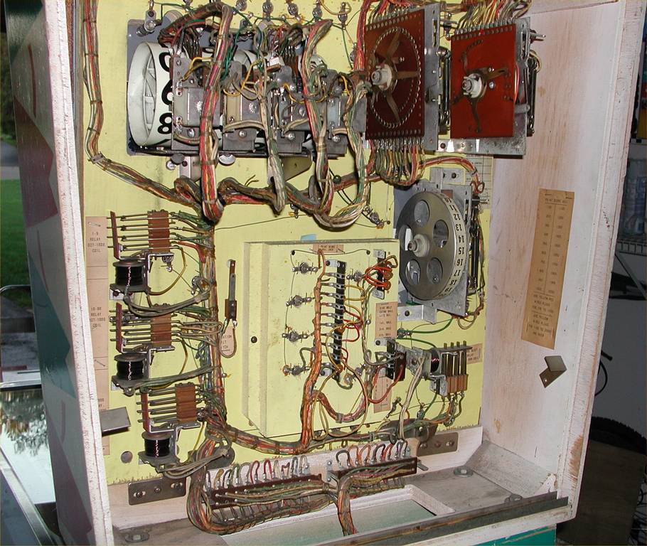
This picture may help
http://www.michiganpinball.com/kicker/Dscn4487_1024.jpg
notice on the ball count unit there is a black mark on the fingers and one on the board
When those 2 line up the ball count unit is at reset position
--Jeff
In relation to the video above ”Ball kicker Coil Firing” ![]()
Check SW E1 on the score motor, this is an NC SW but must open during the Scr Motor cycle. if it doesn't the outhole RE will remain energised and try to kick out the ball each cycle of the score motor.
On other CCM schematic, the only things involved in this part are the Outhole SW the Outhole RE, the Scr Motor and to ball return kicker. I except your game to be the same.
So either the outhole SW is stuck closed after you pressed it with the pen, or SW E1 on the score motor is not opening.
Assuming all wiring is back to way it should be. I don’t think the Ball count unit is causing the continual kicking of the ball return coil here.
Chrisbee-
Thank you again for your reply and help.
We think your suggestion of E1 being stuck closed is correct.
Here's that section of our schematic.
E1_subsection.jpg
We tested the Red and Blue targets that also feed into that switch, and both of those cause the motor to spin forever.
Switch E1 is on the bottom layer, inner ring of motor switches. It's real hard to see.
IMG_0046.jpg
We hooked the multimeter up to what we think are the switch ends.
IMG_0045.jpg
Then we turned the wheel and waited for the beep to stop. It did not stop. This video is evidence, but it's pretty annoying to watch.
Now we're going to try and bend that switch apart without closing/opening the other switches in that stack.
just be sure it is that SW before you adjust, maybe hard to adjust back.
EDIT
Had a thought, while getting ready for bed. Using Continuity on a DMM may not tell you what you want to know. If any SW in the circuit is stuck the buzzer will sound.
Best if you use OHMs set to 200Ω, if not auto scaling. Touch the probes together and check DMM, should be zero or very close. Test E1 again: if the reading is > 10Ω, the SW is open. Zero ohms the SW is closed.
If any SW is stuck you will have a circuit thought coils and transformer.
Chrisbee-
Thank you for that lesson on using the multimeter. We've only used the continuity test so far, and didn't realize that it would beep for connections "above" the switch as well.
When we directly connect the probes, our meter shows a -1 on the left side of the display.
We tested another switch we could see, and saw -1 readings when the switch was open, and 0.0 - 0.2 readings when the switch was closed.
Testing E1 shows a consistent 0.1 or 0.2 for every position of the motor. That suggests, to us, that whatever state E1 is in, it doesn't change. Since it's a normally closed switch and the resistance reading is so low, being stuck closed sounds like a good bet.
We scraped our knuckles on the motor and hit our heads on the playfield trying to get a good look at this switch. Some of us wanted to take the switch that out, but it looks welded to the motor platform.
Quoted from FlinthillMakers:Testing E1 shows a consistent 0.1 or 0.2 for every position of the motor. That suggests, to us, that whatever state E1 is in, it doesn't change. Since it's a normally closed switch and the resistance reading is so low, being stuck closed sounds like a good bet.
That's is a closed SW. The .1 - .2 is the resistance on the test leads or of the probe connection to the test item.
Quoted from FlinthillMakers:We scraped our knuckles on the motor and hit our heads on the playfield trying to get a good look at this switch. Some of us wanted to take the switch that out, but it looks welded to the motor platform.
We should of mentioned, it helps if you are Dbl Jointed,LOL.
We're really confused.
We adjusted switch E1 so that it reads open when the notch lines up.
This did not fix our troubles.
There are three switches that send our game into an score motor loop. This is where the score motor runs and runs, and often some relays fire in the cabinet and head.
Red Target:
Pressing the red target gives 10 points (as it should), but then the motor starts turning and gives an invite stream of 100 points to score and 100 point bells. It sounds like the switch causing this must open/close 3 or 4 times per turn on the score motor.
Blue Target:
When we start a game with the coin door button, the Blue Target relay fires and stays closed. When we press the Blue Target we do NOT get 10 points before it falls into the 100 point loop.
Looking at the motor switch diagram and watching the switches while the bell rings, we think the switch causing this is B2.
B1: 20/30 points relay break
B2: Impulse Replay Unit Reset
Impulse 10/100 Points through Red & Blue Target relays (!!)
Impluse Bank Reset Relay
B3: Match Impulse
Out Hole:
When we press the Outhole switch:
The Blue Target Relay OPENS.
The Outhole Relay CLOSES
The motor starts to spin.
The Outhole kicker starts to fire. Watching the motor, we think this is being caused by C2
C2: Impulse Red/Blue Bumper and Target Score Change Relays
Impulse Ball Return Kick-Out
Impulse Side Hole Kick-Out
Impulse 10c Relay when Set-Up for 5c Game
There are some other issues that don't cause the machine to lock up.
When we press the coin door button, the Blue Target Relay fires and stays closed.
When we press the coin door button, the credit wheel ADDS a credit. Sometimes the wheel doesn't freely turn, but it always moves the +1 coil. When we score a special, the credit wheel also gives +1
The left ball-grab hole often works fine. On some occasions, it seems to stick and gives us 200 points instead of 50.
When we start new games, sometimes the score doesn't reset well. Sometimes it does! But it never gets stuck in score reset. We need to watch more carefully to see if some numbers on particular wheels are the ones that get stuck and then check the switches at those positions.
We have pictures and video of these problems. We could also post better scans of the C2 and B2 sections of the schematic, if that would be helpful.
Our big question is how do we know what's "upstream" of a given switch? For example, it's clear that switch C2 is opening/closing well because the out hole kicker keeps firing. But how do we find the part of the schematic/wiring that's responsible for making that stop?
Thanks again for all your help. We've been able to "play" games by covering up the out hole switch and have had a lot of fun!
Quoted from FlinthillMakers:Our big question is how do we know what's "upstream" of a given switch? For example, it's clear that switch C2 is opening/closing well because the out hole kicker keeps firing. But how do we find the part of the schematic/wiring that's responsible for making that stop?
Most schematic will have a diagram of the Score motor, showing the SWs wire colours and timing. The schematic I have for Kicker does not have this. Anyway, if you have this section of the schematic, find the SW “C2”, see what it is associated with. Find then on the schematic and what is between the SW “C2” and the associated part, is what’s upstream of Switch “C2”.
On Kicker I can see two coils that can fire, associated with “C2”. The Call Count stepper unit step up and reset coils. So in the attached schematic, the Outhole RE must be energised before “C2” closes otherwise the coil will not fire when “C2” does close.
Hope this helps.
Quoted from FlinthillMakers:Red Target:
Pressing the red target gives 10 points (as it should), but then the motor starts turning and gives an invite stream of 100 points to score and 100 point bells. It sounds like the switch causing this must open/close 3 or 4 times per turn on the score motor.
Find the Score Motor on the schematic (around about J5) – All the Relays to the left of it (Up to the thick green wire) can make the SCR Motor start (there are 10 of them), SW “A2” will keep it running until it completes a cycle.
From this we can see that the Red Target is not directly responsible for the score motor starting.
But one of the REs there is staying energised.
Watch the REs once the Scr Motor is in its endless loop, see which one does not cycle (Stays Energised). Once you know this, find on the RE schematic and see which SWs can keep it energised.
Note there can be more than one RE at fault.
Best of luck, I just got my "Chicago Coin" to fire up for the first time tonight and start a game. All I can offer is clean, clean, and clean again those score reel switches and boards. I searched for demons long after I thought they were clean, and still, the culprit ended up being a bad connection after ruling it out time and again.
Wanna join the discussion? Please sign in to reply to this topic.

Great to see you're enjoying Pinside! Did you know Pinside is able to run without any 3rd-party banners or ads, thanks to the support from our visitors? Please consider a donation to Pinside and get anext to your username to show for it! Or better yet, subscribe to Pinside+!

This page was printed from https://pinside.com/pinball/forum/topic/chicago-coin-kicker/page/2 and we tried optimising it for printing. Some page elements may have been deliberately hidden.
Scan the QR code on the left to jump to the URL this document was printed from.
 Fairfax, VA