(Topic ID: 79267)
Linked Games
 Creature from the Black Lagoon
Bally, 1992
Creature from the Black Lagoon
Bally, 1992
Topic Gallery
 Elk Grove Village, IL
Quoted from j_m_:if you're talking about the mod that I started on about 3-4 years ago, it's this
[quoted image]
the thought is to replace all of the playfield plastics with 4D smart LCD panels, light up & animate the appropriate sections when a mode is running.
I've continued to pick this up, work on it a bit and then shelve it multiple times. the coding has been complete for triggering everything for a while so I reached out to stumblor for assistance on producing the boards to replace the original lamp boards.
if I do end up completing and marketing it, the mod will be plug and play and completely reversible, however the cost will be kind of pricey due to cost the amount of materials involved and the time that I've invested in it.
Very cool! I’m in if you decide to do it.
Quoted from j_m_:if you're talking about the mod that I started on about 3-4 years ago, it's this
[quoted image]
the thought is to replace all of the playfield plastics with 4D smart LCD panels, light up & animate the appropriate sections when a mode is running.
I've continued to pick this up, work on it a bit and then shelve it multiple times. the coding has been complete for triggering everything for a while so I reached out to stumblor for assistance on producing the boards to replace the original lamp boards.
if I do end up completing and marketing it, the mod will be plug and play and completely reversible, however the cost will be kind of pricey due to cost the amount of materials involved and the time that I've invested in it.
Nice overall design, but I have to ask... Why a 4D display ??? Given the amount of pixel change between each frame, an SPI screen would do just fine, no ? And they are way cheaper, and can be controlled by an Arduino. You can add to it one optocoupler, a few diodes and resistors for triggering on insert status.
Am I missing something ?
Marco1973 Pretty sure that diode spanning the lugs on that coil in not factory, and if its not causing this problem may be causing others.
Here is mine:
3d-92 (resized).jpg
Also decided on chrome shooter housing, good balance... however on a TZ Mikespinball i waould agree all black is the way to go...
3d-93 (resized).jpg
Quoted from Ashram56:Nice overall design, but I have to ask... Why a 4D display ??? Given the amount of pixel change between each frame, an SPI screen would do just fine, no ? And they are way cheaper, and can be controlled by an Arduino. You can add to it one optocoupler, a few diodes and resistors for triggering on insert status.
Am I missing something ?
why?? because that's what I chose. when I started working on the project (over 4 years ago), I saw them and thought that I could do something cool with them. additionally, with the 4D displays I was able to do this with one piece of hardware per signpost (other than the pcb to interface between the 4D display and existing wiring harness. plus, this was originally meant as a project for my machine and mine alone.
yes, the SPI displays are about $15+ each (about 25% of the 4D display cost for the same size/resolution), but you still need to add in the arduino and interface everything together. with an arduino solution, if it fails, then everything fails. with the 4D displays, each is independent but yes, each could fail (just as each SPI display could fail). pluses and minuses with each.
Quoted from j_m_:why?? because that's what I chose. when I started working on the project (over 4 years ago), I saw them and thought that I could do something cool with them. additionally, with the 4D displays I was able to do this with one piece of hardware per signpost (other than the pcb to interface between the 4D display and existing wiring harness. plus, this was originally meant as a project for my machine and mine alone.
yes, the SPI displays are about $15+ each (about 25% of the 4D display cost for the same size/resolution), but you still need to add in the arduino and interface everything together. with an arduino solution, if it fails, then everything fails. with the 4D displays, each is independent but yes, each could fail (just as each SPI display could fail). pluses and minuses with each.
Thanks for the explanation, I was thinking there might be a technical reason (SPI screens framerate are limited because of the SPI speed interface for ex). Apologies if my question might have sounded rude, that was not the intent (lost in translation one would say). Indeed for a one-off 4G displays are rather a nice solution. But boy are they expensive. I managed to snag a uoled-128-g2 at 25 euros on ebay, but official price list is more in the range of 50 euros for that model (at least on Mouser in Europe).
Fortunately things have improved on the SPI side of things, with an atsamd51 at 120Mhz I'm able to achieve 8FPS for mjpg type video decoding at 240x240, I hope to be able to achieve 10FPS and more on ESP32 (80ms are taken for screen SPI update). That's for pure video content where each pixel in the frame is updated at each cycle. With content where a differential pixel update can take place (since SPI displays have their own frame buffer), I would assume you can achieve much higher frame rate (at the expense of engineering investment though).
Which size / resolution did you find was required for that sign ?
the 3.5" (diagonal) 4D screens that I'm using support 320x480 and I've been able to get 12-15fps out of them (which allow the animations to run very smooth)
https://4dsystems.com.au/products/4d-intelligent-hmi-display-modules/gen4-hmi-display-modules/gen4-ulcd-35d
the earliest test that I ran with one of the displays which has touch screen support (allowing me to even trigger more than one animated section at a time), the frame rate held at that 12-15fps
Devilsmuse The plastic showed up today! Thank you very much! Well packaged and protected too! Thank you!!!
1 (resized).jpg
Oh, and speak of the devil, not devilsmuse, but uh... well it's a figure of speech. I was just talking about the Chase Echo. Looky what else showed up today! Check out the sexy hot pink wiring looms! I was super excited to see those! Ha ha! I'll probably install on the weekend and have a review for everyone in about a week.
2 (resized).jpg
Thank you both! This is going to be an exciting weekend!
 Bolzano
Thank you very much for the help.
I cutted off the diode and the fuse is not blowing anymore.
But...there is always a "but"... now when turning on the pin a buzz appears after some seconds, increasing its volume more and more, till I shut down the pin cause it seems to are going to explode. At the same time as the buzz appears, the DMD starts to flicker, increasing the flickering with the volume of the buzz.
I don't know if I can post a small video or audio so I hope the xplanation was good ![]() . Suggestions ?
. Suggestions ?
Either a problem on the cpu or somewhere in the wiring - try to disconnect the wires at the bottom of the cpu (direct switch input) and see if it still does it, if so, then probably an error on the cpu board somewhere..
Here a link to a short video I made.
JayDee in a few minutes will I check where the buzz comes from.
aeneas I don't understand from which cables are you talking about
But I need to say before cutting off the diode, the buzz was not present even if without the circuit of the fuse 103 cause it was blown
 Melbourne
Quoted from Marco1973:It's the coil I cutted off the diode. It remains "closed" going on to pull, without stopping pulling.
JayDee you were right.
Firstly check your coil is an AE-26-1200 and see if the Q24 (TIP102) on the driver board has shorted
Testing a TIP-102 transistor (with the power to the machine off)
Set the DMM to diode check
Place the black lead on the center leg
Place the red lead on each of the flanking legs in turn
A measurement between .5 and .7 should be displayed
Readings outside of this range (generally dead shorts) indicate the part has failed.
Manny65 Thank you for learning me how to test a Tip transistor.
The left leg shows 576 without "bip". The right leg shows 000 with "bip".
I think I need to change the TIP.
I have here a second power driver. I will try to change it later (here is actually 12.00 - time to lunch). I'm hungry ![]()
Manny65 You were right. The TIP was bad. I changed power board and now functions everything or at least all the things I tested
![]()
Afret dismounting the old board I saw the previous owner made some BAD works on it, including the TIP that was bad. So, problem solved.
Quoted from Marco1973:manny65 You were right. The TIP was bad. I changed power board and now functions everything or at least all the things I tested
Afret dismounting the old board I saw the previous owner made some BAD works on it, including the TIP that was bad. So, problem solved.
Great work - glad you got it sorted
 London
On with the next problem.
I tested all the lamps. All ok, except the one you see in the picture.
Trough the test they are called "string 5".
They are connected to the power board to J121-6 and J121-11 trough the violet-white/violet cables.
They don't want to light up.
Solutions ?
string5 (resized).pngQuoted from Soulrider911:Finally got my mirrored back glass in ... took a lot of trimming on the... trim to get it to fit right
[quoted image]
Then a month or so later it was back?
Anyone know why it came down and went back up? Copyright?
Are the glasses the same?
Quoted from wolftownjeff:The glass went up for sale for about a week or two and I bought one. Then it disappeared from the web site.
Then a month or so later it was back?
Anyone know why it came down and went back up? Copyright?
Are the glasses the same?
The backglass is just a copy of the translite with some areas mirrored. Nothing to change.
My guess is cpr pulled it due to demand. The art is printed at this point but the mirroring isn't so most likely made in batches.
Quoted from Marco1973:On with the next problem.
I tested all the lamps. All ok, except the one you see in the picture.
Trough the test they are called "string 5".
They are connected to the power board to J121-6 and J121-11 trough the violet-white/violet cables.
They don't want to light up.
Solutions ?[quoted image]
Does each wire have continuity from connector to first light socket? Is each wire seated correctly in board connector and not pulled out a little? Is connector properly seated on the board? No bent pins?
Those are the easy things to check first.
Those are controlled lamps on a row so, if it's not a simple wire issue, I'd guess you probably have a problem on the lower right section of the power driver board. You can see the row and associated drivers in the manual.
Added over 3 years ago:Quoted from robey99:Has any had the issue where the back box baffle lights do not chase. Won’t even turn on. All the other bulbs work as well as the flashers. Thanks for the help.
Quoted from JayDee:Does each wire have continuity from connector to first light socket? Is each wire seated correctly in board connector and not pulled out a little? Is connector properly seated on the board? No bent pins?
Those are the easy things to check first.
JayDee you were again right. I noted while pushing the board, there was light. So I tested the cables how you suggested, and they were ok.
So I dismounted the board (again...) and made new soldering on the connectopr and on the GI fuses. Then the problem vanished. Thank you again.
Last problem, I hope.
Is it normal that the bulbs on the stripes around the central ramp are not all lighting when I'm making a test of GI ?
Bulbs are ok. Cable is ok from bulb socket till board under the playfield (JayDee learns
![]() ), I mean I tested continuity.
), I mean I tested continuity.
I noted, on the stripes at the left side of the playfield, the first and the fifth bulb of both stripes won't light up.
They have the same + cable, the orange/black (dashes, not stripes).
stripes (resized).pngthere are 24 bulbs in the chase section, and I believe that they operate in sequences of 4 bulbs at a time (meaning that when they are in "chase" sequence, bulbs 1, 5, 9, 13, 17 and 21 are lit then 2, 6, 10, 14, 18 and 22, then 3, 7, 11, 15, 19 and 23 and finally 4, 8, 12, 16, 20 and 24 are lit. (then the sequence repeats.
if bulbs 1, 5, 9, 13, 17 and 21 are never lighting up, it's probably something on your chase light board under the playfield. it might be something as easy as reflowing the header on the connector.
Quoted from Marco1973:j_m_
Thank you for your help.
When enter the test mode and run the General Illumination, all bulbs must light.
Those would not light up.
I changed the board under the playfield, but the bulbs still don't work.
Is there not multiple fuses for those bulbs?
Thought I would share this. I am in the process of my DIY poster mod, thanks to swinks for the wonderful instructions. I decided to make a photoshop template for the static posters. This make it easy to change the posters in photoshop as the posters are made using smart objects. Also added cut lines for trimming when you print. Enjoy!
Here is the Dropbox link to the photoshop file: https://www.dropbox.com/s/kg5l2noh5m1c6n3/CFTBLPoster.psd?dl=0
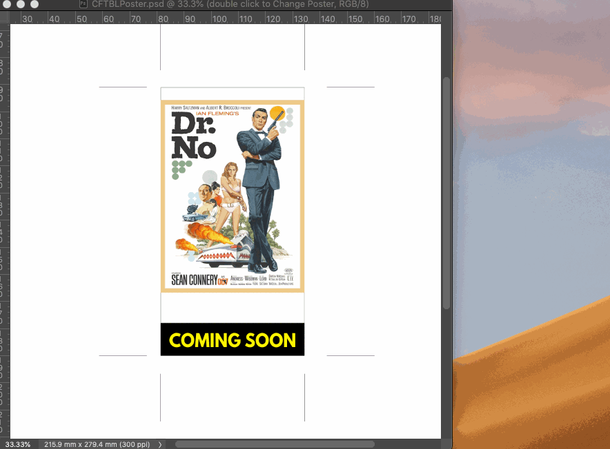 poster.gif
Quoted from fiberdude120:Is there not multiple fuses for those bulbs?
No, the same fuses for the general illumination, even if divided in parts.
Anyway i made new solder here too on the small board under the playfield. Problem vanished.
Quoted from Marco1973:No, the same fuses for the general illumination, even if divided in parts.
Anyway i made new solder here too on the small board under the playfield. Problem vanished.
If I remember correctly I had a problem with my chase lights not working and I purchased a new board.. Low and behold there was a fuse that supplied power to those lights and had nothing to do with general illumination. Just my 2 cents.
Quoted from fiberdude120:If I remember correctly I had a problem with my chase lights not working and I purchased a new board.. Low and behold there was a fuse that supplied power to those lights and had nothing to do with general illumination. Just my 2 cents.
Light will completely not work if there were a fuse problem. in this case only some were not working. But good to know for the n ext time ![]()
I have been having issues with my Kiss shot lately where like 15% of the time it bounces back out. I did recently put in a cliffy, at first I thought the gate was loose but tightening it only helped a tiny bit.
Is there something I'm missing like in the gate positioning??
Is this just a common issue with the cliffy?
Any insight would help, thanks!
Quoted from PoogiePrincess:I have been having issues with my Kiss shot lately where like 15% of the time it bounces back out. I did recently put in a cliffy, at first I thought the gate was loose but tightening it only helped a tiny bit.
Is there something I'm missing like in the gate positioning??
Is this just a common issue with the cliffy?
Any insight would help, thanks!
I have Cliffy's on my KISS, and Snackbar. If the Cliffy is not sitting flat prior to screwing everything down then you'll have issues. Don't take any short cuts when installing. Clear the area. Position the Cliffy properly so it sits flush and so that it is not warped or sitting awkwardly. Then re-assemble everything.
I made the mistake of trying to take short cuts when I installed the Cliffy on my Snackbar hole and I started getting rejects. The ball also started getting hung up on the clip portion. Recently I took that area apart again, this time I took my time, and the Cliffy is seated perfectly now. I did drill out one of the holes a bit larger, but not by much. It sits perfectly now, and my shots into the snackbar hole no longer get stuck, or rejected.
If you are able to take a picture that may help us too.
Quoted from Fifty:I have Cliffy's on my KISS, and Snackbar. If the Cliffy is not sitting flat prior to screwing everything down then you'll have issues. Don't take any short cuts when installing. Clear the area. Position the Cliffy properly so it sits flush and so that it is not warped or sitting awkwardly. Then re-assemble everything.
I made the mistake of trying to take short cuts when I installed the Cliffy on my Snackbar hole and I started getting rejects. The ball also started getting hung up on the clip portion. Recently I took that area apart again, this time I took my time, and the Cliffy is seated perfectly now. I did drill out one of the holes a bit larger, but not by much. It sits perfectly now, and my shots into the snackbar hole no longer get stuck, or rejected.
If you are able to take a picture that may help us too.
Thanks! I'll fiddle with it and see if I can refit the cliffy
After a couple of years of trying I am happy to say I am now a member. I bought a machine that looks fantastic but I need to troubleshoot a couple of problems to get it up and running. One question right off the bat, I thought that my left ramp was broken as it has a gap in the left side but looking at photos of others I think it is supposed to be this way. I am just curious how the ramp is supported on the left side as it is just resting on the sheet metal bracket at that point and it can just float around vs. being screwed down. Photo attached, please advise if this is correct of if something is missing. I am also curious if the playfield is original, it looks absolutely perfect which had me thinking it was a reproduction but then i saw the Jan 1993 stamp on the edge and I am having second thoughts, perhaps this has never seen an arcade? I have attached a photo of that and the barcode on the playfield, if anyone has clues as to origin I would love to know. Thanks!
IMG_4562 (resized).JPGIMG_4565 (resized).JPGIMG_4566 (resized).JPGQuoted from Deleenhe:After a couple of years of trying I am happy to say I am now a member. I bought a machine that looks fantastic but I need to troubleshoot a couple of problems to get it up and running. One question right off the bat, I thought that my left ramp was broken as it has a gap in the left side but looking at photos of others I think it is supposed to be this way. I am just curious how the ramp is supported on the left side as it is just resting on the sheet metal bracket at that point and it can just float around vs. being screwed down. Photo attached, please advise if this is correct of if something is missing. I am also curious if the playfield is original, it looks absolutely perfect which had me thinking it was a reproduction but then i saw the Jan 1993 stamp on the edge and I am having second thoughts, perhaps this has never seen an arcade? I have attached a photo of that and the barcode on the playfield, if anyone has clues as to origin I would love to know. Thanks!
[quoted image][quoted image][quoted image]
Welcome! Playfield looks to be original. You have the 'light' pink version of the playfield.
That spiral ramp just rests on the sheet metal. Yours is correct. I thought the same thing when I purchased mine. The sheet metal is there to ensure the ramp isn't damaged when you lift the playfield.
Your flippers need to be aligned. Yours are too far forward. Remove the flipper rubber, stick a toothpick in the hole just behind them, rest the rubberless flipper on the toothpick and then tighten it up. Make sure you have a credit card side gap between the flipper bushing and the bottom of the flipper too. You can use a cut up credit card to do this or the gap tool from many pinball manufacuturers.
https://www.marcospecialties.com/pinball-parts/03-8194
Quoted from Deleenhe:After a couple of years of trying I am happy to say I am now a member. I bought a machine that looks fantastic but I need to troubleshoot a couple of problems to get it up and running. One question right off the bat, I thought that my left ramp was broken as it has a gap in the left side but looking at photos of others I think it is supposed to be this way. I am just curious how the ramp is supported on the left side as it is just resting on the sheet metal bracket at that point and it can just float around vs. being screwed down. Photo attached, please advise if this is correct of if something is missing. I am also curious if the playfield is original, it looks absolutely perfect which had me thinking it was a reproduction but then i saw the Jan 1993 stamp on the edge and I am having second thoughts, perhaps this has never seen an arcade? I have attached a photo of that and the barcode on the playfield, if anyone has clues as to origin I would love to know. Thanks!
[quoted image][quoted image][quoted image]
Awesome! Let’s get some wider shots of that bad boy!
Thanks Fifty , I will line those up (I did wonder what those holes were for on my Diner!). Here's some more shots. The cabinet is new with vinyl graphics vs paint but looks amazing. It has the Mike D hologram mod but I have taken it out, it is not getting power and the flippers are not working so I think there is a broader electrical problem to figure out. I'm sure I will have some questions on that. Another question (one of many), the black sockets in the backbox are mostly empty, not sure why, are these different than the white ones? Thanks.
IMG_4571 (resized).JPGIMG_4573 (resized).JPGIMG_4575 (resized).JPGIMG_4576 (resized).JPGIMG_4577 (resized).JPGIMG_4578 (resized).JPGQuoted from robey99:The black ones are for flasher bulbs.
Yes. They were probably flashing whenever the flippers were being pressed. I recently changed mine to LED and that what mine is doing. I can either change them back to incandescents or add a diode onto the each LED flasher.
Looks like you have a white 3D printed bracket in your backbox as well. I've been thinking of doing that as well.
The lamp covers (silicon caps) on your signs are incorrect. Not that it really matters. The lights should go
WHITE (top)
GREEN
YELLOW
on the two outer signs.
WHITE (top)
RED
GREEN
YELLOW
I may get people disagreeing with me on this, but as soon as you start a multiball you will realise this is the proper colour order.
Quoted from Fifty:Yes. They were probably flashing whenever the flippers were being pressed. I recently changed mine to LED and that what mine is doing. I can either change them back to incandescents or add a diode onto the each LED flasher.
Looks like you have a white 3D printed bracket in your backbox as well. I've been thinking of doing that as well.
The lamp covers (silicon caps) on your signs are incorrect. Not that it really matters. The lights should go
WHITE (top)
GREEN
YELLOW
on the two outer signs.
WHITE (top)
RED
GREEN
YELLOW
I may get people disagreeing with me on this, but as soon as you start a multiball you will realise this is the proper colour order.
Looks like I need to go put a game on the machine to "realise" why ... lol
Quoted from Deleenhe:Thanks fifty , I will line those up (I did wonder what those holes were for on my Diner!). Here's some more shots. The cabinet is new with vinyl graphics vs paint but looks amazing. It has the Mike D hologram mod but I have taken it out, it is not getting power and the flippers are not working so I think there is a broader electrical problem to figure out. I'm sure I will have some questions on that. Another question (one of many), the black sockets in the backbox are mostly empty, not sure why, are these different than the white ones? Thanks.
[quoted image][quoted image][quoted image][quoted image][quoted image][quoted image]
Nice man, I don’t know about “HUO” but it does look like someone poured a lot of love and money into that one!
Promoted items from Pinside Marketplace and Pinside Shops!
Reply
Wanna join the discussion? Please sign in to reply to this topic.

Hey there! Welcome to Pinside!
Donate to PinsideGreat to see you're enjoying Pinside! Did you know Pinside is able to run without any 3rd-party banners or ads, thanks to the support from our visitors? Please consider a donation to Pinside and get anext to your username to show for it! Or better yet, subscribe to Pinside+!
