(Topic ID: 285624)

Bally super sonic troubleshooting

By noopy

3 years ago


Topic Heartbeat

Topic Stats

  • 15 posts
  • 6 Pinsiders participating
  • Latest reply 3 years ago by Quench
  • No one calls this topic a favorite

You

Linked Games

Topic Gallery

View topic image gallery

SDB_PB3.gif
IMG_1414.gif
SolenoidOrder_Supersonic.png
#1 3 years ago

Hey All,

I'm new to pinball, I picked up a bally supersonic that didn't work as my first pin.

Turns out the battery on the MPU board had leaked and done some damage. When booting I only got 2 led flashes; there was some corrosion damage to one of the sockets; I ran a jumper wire from two traces to the correct legs of one of the chips and now the machine boots completely. I'll be ordering the Bally Battery corrosion repair kit from GPE as soon as they start taking orders.

Now that the machine boots I ran the diagnostic tests and am having an issue where the saucer and outhole solenoids do not fire. If I jumper the solenoids to ground they fire fine. When I jumper the transistor on the SDB they also fire.

I found a thread on here where somone had a similar problem and got some advice on how to test the SDB further:

https://pinside.com/pinball/forum/topic/1978-bally-outhole-kicker-dead

Grab a jumper wire and connect one end to test point TP6 on the solenoid driver board (SDB).
Very briefly touch the other end of the jumper wire on the banded side of diode CR4 on the SDB. Does the outhole kicker activate?

Next going upstream, remove the jumper wire from TP6 and connect it to the GND test point on the SDB.
Very briefly touch the other end of the jumper wire on pin 8 of U1 on the SDB. Does the outhole kicker activate?

I followed Quench's testing procedure above and the solenoid fired both times. If I understand the thread correctly this leads be to believe the SDB and U1 chip are fine and that for some reason the SDB is not getting the signal to fire the outhole or saucer from the MPU board. In the above thread the issue was one of the 4 solenoid signal wires from the MPU board was not connected correctly. On my machine those 4 wires are all in the correct spots.

I'm guessing maybe one of those 4 wires is not making contact. I tested the header pins for continuity to there respective traces on the SDB and MPU boards and they check out fine so if it is a connection it is in the connectors; I'll be repinning them as soon as I get connectors from GPE.

Is there anything else I can test or that you all might suspect?

Thanks!

#2 3 years ago

Repinning would be the first step, especially with battery damage.

#3 3 years ago
Quoted from noopy:

I'm guessing maybe one of those 4 wires is not making contact.

Is the knocker also not working? If yes, suspect a connection issue with the red-white wire from the MPU board J4 pin 1 to the solenoid driver board J4 pin 3.

But as Billc479 mentioned, you're better off re-terminating MPU J4 connector as battery corrosion tends to foul it. Check the J4 pin header for corrosion too.

#4 3 years ago

Invest in Alteks boards if you are going to keep the game. An acid damaged board can be repaired but never "fixed." You will have problems over and over. Altek boards are as foolproof as a board can be and they have NEW technology rather than 40 year old first generation electronics.

#5 3 years ago

The signal from the mpu to the SD board is probably incomplete. Repin and resolder the connectors. That might get you going.

#6 3 years ago

Thanks everyone.

Quoted from Quench:

Is the knocker also not working? If yes, suspect a connection issue with the red-white wire from the MPU board J4 pin 1 to the solenoid driver board J4 pin 3.
But as Billc479 mentioned, you're better off re-terminating MPU J4 connector as battery corrosion tends to foul it. Check the J4 pin header for corrosion too.

Quench , I ran the test again and noticed the drop target is firing when the knocker is supposed to but the drop targets fire again when they are supposed to. What do you think that means?

I removed the boards and checked the traces on j4 pin 1-4 on the mpu board with a meter and they seem fine. The sdb looks good too.

#7 3 years ago

Solenoids firing out of order (compared to the manual numbers) in solenoid test is definitely a sign of miscommunication between the CPU board and SDB. Rebuild female J4 connectors on both CPU board and SDB and see where you're at.

Do one pin at a time. Clip one wire, strip it and crimp it, insert in new housing. So you don't lose track and have to look at the manual.

#8 3 years ago
Quoted from noopy:

I ran the test again and noticed the drop target is firing when the knocker is supposed to but the drop targets fire again when they are supposed to. What do you think that means?

It confirms a bad connection on that red-white wire I mentioned. This is more likely a wire connection issue rather than a board issue. Bare with me:

There's four momentary solenoid select signals from the MPU board to the solenoid Driver Board (SDB). These are signals PB0, PB1, PB2 and PB3 which come from pins 4, 3, 2, 1 respectively on J4 of the MPU board and go to pins 6, 5, 4, 3 respectively at J4 of the SDB.
From the SDB schematic, below are the four PB0, PB1, PB2 and PB3 signal states and which solenoids the combination of states select. The four digits in the left column are binary numbers - "0" means zero volts, "1" means 5 volts.

The designated solenoids listed are what should activate, the right column shows the incorrect solenoid activation you're getting. You can see the binary value for the knocker and drop target reset differ in the state of the PB3 signal. Also PB3 needs to go to zero volts for the outhole and saucer to activate.

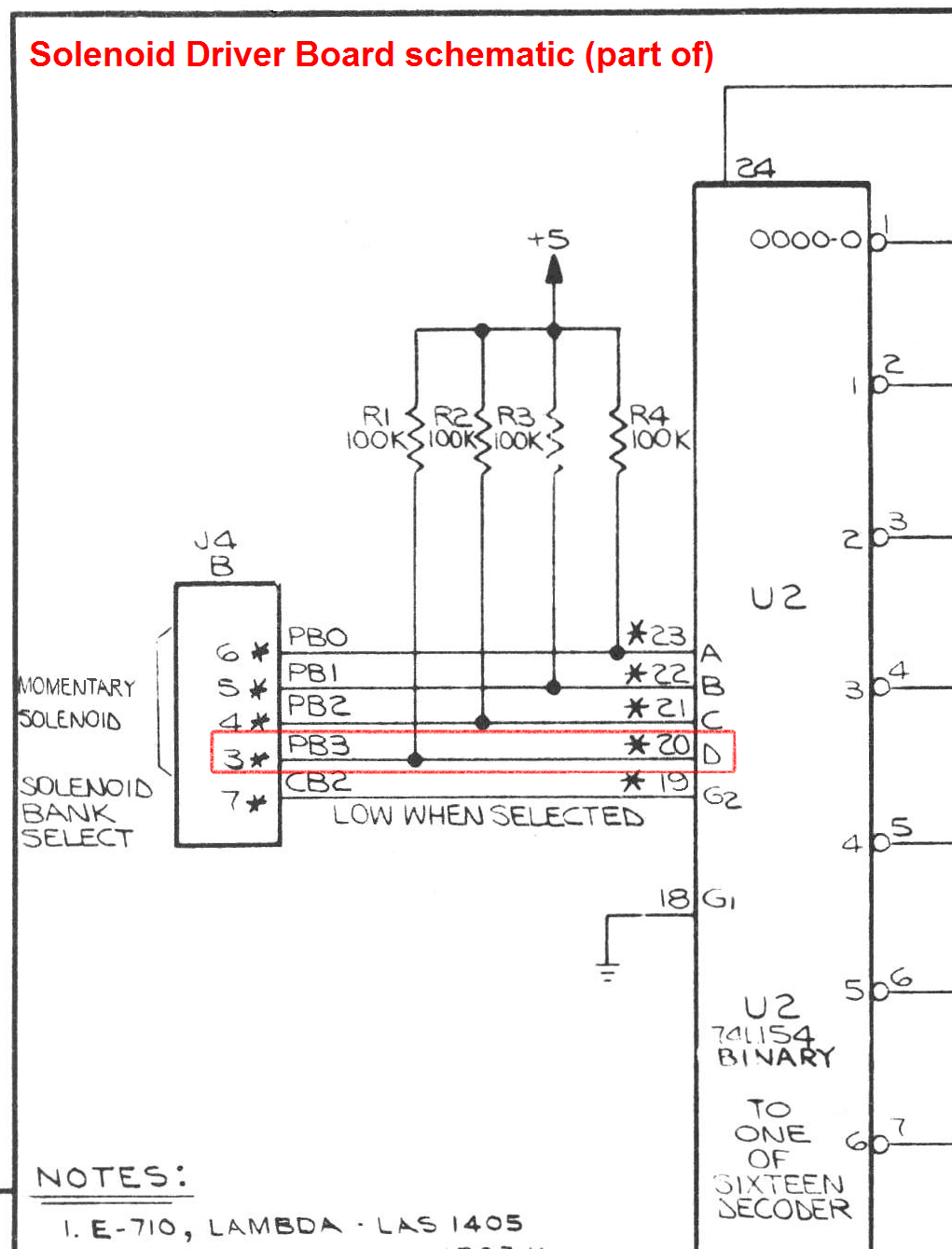
The table shows the PB3 signal is not getting from the MPU board to the SDB and the SDB is always seeing PB3 as a "1" (5 volts). This is a red-white wire from MPU J4 Pin 1 to the SDB J4 Pin 3. Most likely one end of that wire has a bad crimp terminal and more likely on the MPU board side of the cable.

SolenoidOrder_Supersonic.pngSolenoidOrder_Supersonic.png

Until you get your crimp terminals from GPE, you can try a short term repair.
See the few posts at this link on how to remove the wire crimp terminals from the connector housing:
https://pinside.com/pinball/forum/topic/vids-guide-re-populating-playfields#post-4545041

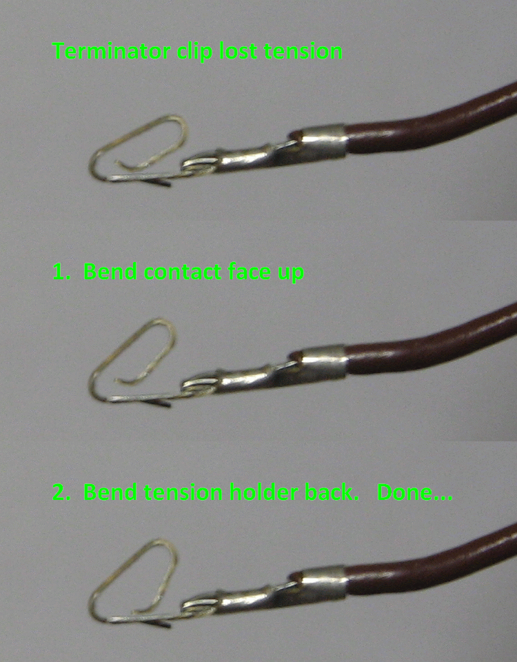
Then try giving the terminal some extra tension, if it's badly corroded/broken, you might be out of luck.

IMG_1414.gifIMG_1414.gif

#9 3 years ago
Quoted from Quench:

It confirms a bad connection on that red-white wire I mentioned. This is more likely a wire connection issue rather than a board issue. Bare with me:
There's four momentary solenoid select signals from the MPU board to the solenoid Driver Board (SDB). These are signals PB0, PB1, PB2 and PB3 which come from pins 4, 3, 2, 1 respectively on J4 of the MPU board and go to pins 6, 5, 4, 3 respectively at J4 of the SDB.
From the SDB schematic, below are the four PB0, PB1, PB2 and PB3 signal states and which solenoids the combination of states select. The four digits in the left column are binary numbers - "0" means zero volts, "1" means 5 volts.
The designated solenoids listed are what should activate, the right column shows the incorrect solenoid activation you're getting. You can see the binary value for the knocker and drop target reset differ in the state of the PB3 signal. Also PB3 needs to go to zero volts for the outhole and saucer to activate.
The table shows the PB3 signal is not getting from the MPU board to the SDB and the SDB is always seeing PB3 as a "1" (5 volts). This is a red-white wire from MPU J4 Pin 1 to the SDB J4 Pin 3. Most likely one end of that wire has a bad crimp terminal and more likely on the MPU board side of the cable.
[quoted image]
Until you get your crimp terminals from GPE, you can try a short term repair.
See the few posts at this link on how to remove the wire crimp terminals from the connector housing:
https://pinside.com/pinball/forum/topic/vids-guide-re-populating-playfields#post-4545041
Then try giving the terminal some extra tension, if it's badly corroded/broken, you might be out of luck.
[quoted image]

Thanks. I removed the wire from the connector housing on both ends, neither looked corroded and I retensioned them. I also tested the connection on the mpu side by checking for continuity from pin1’s resistor on the mpu board with j4 plugged in and pin3 on the SDB connector, it checked out. Is there any component or connection on the mpu board I could check that could have failed that would cause it to not be able to pull that line low?

#10 3 years ago
Quoted from noopy:

Is there any component or connection on the mpu board I could check that could have failed that would cause it to not be able to pull that line low?

It's extremely rare for component failure to cause this. The solenoid driver board pulls the PB3 signal high via resistor R1. It's the responsibility of the MPU board to pull it low when needed.

How are you testing continuity? Some meters set on diode/beep mode will indicate continuity even when there's 150 ohms resistance which is a false reading.

With the machine OFF, how much resistance do you measure between the MPU board at pin 13 of U11 to the solenoid driver board at pin 20 of U2?

Have you got a logic probe?

#11 3 years ago
Quoted from Quench:

It's extremely rare for component failure to cause this. The solenoid driver board pulls the PB3 signal high via resistor R1. It's the responsibility of the MPU board to pull it low when needed.
How are you testing continuity? Some meters set on diode/beep mode will indicate continuity even when there's 150 ohms resistance which is a false reading.
With the machine OFF, how much resistance do you measure between the MPU board at pin 13 of U11 to the solenoid driver board at pin 20 of U2?
Have you got a logic probe?

No logic probe. I tried to measure resistance between those two pins and got an open loop. I checked the boards separately and was getting 466ohm resistance between pin 13 of u11 and pin 1 of the j4 header but get an open loop on the sdb. Where on the board is pin 20 of U2 supposed to connect to? I couldn’t tell from looking at the board.

I did check that pin3 on J4 was good but don’t know what else to test.

#12 3 years ago

Oops double post

#13 3 years ago
Quoted from noopy:

I checked the boards separately and was getting 466ohm resistance between pin 13 of u11 and pin 1 of the j4 header

Yes, there's a 470 ohm resistor on the MPU board between U11 pin 13 and J4 pin 1. All good there.

Quoted from noopy:

Where on the board is pin 20 of U2 supposed to connect to?

On the Solenoid Driver Board, U2 pin 20 connects to J4 pin 3 which is the problem signal in question. How did you test pin 3 of J4 as being good?
Check the soldering on the back of the SDB where the J4 pin header is. Sometimes the soldering on the pin header fractures/cracks.

SDB_PB3.gifSDB_PB3.gif

#14 3 years ago

Quench, you are the man! Thank you so much.

I looked at the back of the board more carefully and although the pin was soldered firmly in place there was a small crack as soon as the solder "blob" contacted with the trace. Everything works now. If your ever in the SF bay area I owe you a beer.

#15 3 years ago

Great to hear, I have a soft spot for Supersonic

Promoted items from Pinside Marketplace and Pinside Shops!
$ 12.00
Electronics
Yorktown Arcade Supply
 
From: $ 169.00
From: $ 170.00
$ 22.50
$ 18.00
Electronics
Yorktown Arcade Supply
 
From: $ 2.99
$ 10.95
Eproms
Pinballrom
 
$ 18.95
Eproms
Pinballrom
 

Reply

Wanna join the discussion? Please sign in to reply to this topic.

Hey there! Welcome to Pinside!

Donate to Pinside

Great to see you're enjoying Pinside! Did you know Pinside is able to run without any 3rd-party banners or ads, thanks to the support from our visitors? Please consider a donation to Pinside and get anext to your username to show for it! Or better yet, subscribe to Pinside+!


This page was printed from https://pinside.com/pinball/forum/topic/bally-super-sonic-troubleshooting and we tried optimising it for printing. Some page elements may have been deliberately hidden.

Scan the QR code on the left to jump to the URL this document was printed from.