(Topic ID: 269804)

Bally Lost World-Solenoid/Playfield Lights-Power Issue

By Millennial-Pin

3 years ago


Topic Stats

You

Linked Games

Topic Gallery

View topic image gallery

RectifierBoard_TransformerPoints1.gif
RectifierBoard_J1_Playfield_Connector.gif
image (resized).jpg
image2 (resized).jpeg
image1 (resized).jpeg
image3 (resized).jpeg
image0 (resized).jpeg
image9 (resized).jpeg
image8 (resized).jpeg
467b6758a7e063c300ea41de8e542b3491183f7f (resized).jpg
image7 (resized).jpeg
image6 (resized).jpeg
image5 (resized).jpeg
image4 (resized).jpeg
image3 (resized).jpeg
image2 (resized).jpeg
#1 3 years ago

Grettings All,

Longtime reader, first time poster. During COVID I undertook the process of refreshing my Alien Star and Lost World (1978) machines. Alien Star went fine new lights rubbers, pop bumper and wax. When I dug into the Lost World I encountered a number of unfortunate hacks in the backbox, the game ran 90% fine as-was but it seems that someone over the years had made numerous adjustments to the AS-2518 Transformer board, before pictures below.

I decided that it would be a fun project to roll back these hacks, re-pin the molex and insert new fuses. When all said and done I checked my transformer board TPs and everything was within acceptable rage. However, now my solenoids will not power up and playfield lights (only scoring lights) will also not power up.

Any pointers or suggestions would be greatly appreciated. I am new to pinball wiring but capable. I have also attached a wiring diagram that I found useful in checkig my work on the burned out connectors.

467b6758a7e063c300ea41de8e542b3491183f7f (resized).jpg467b6758a7e063c300ea41de8e542b3491183f7f (resized).jpgimage0 (resized).jpegimage0 (resized).jpegimage1 (resized).jpegimage1 (resized).jpegimage2 (resized).jpegimage2 (resized).jpegimage3 (resized).jpegimage3 (resized).jpegimage4 (resized).jpegimage4 (resized).jpegimage5 (resized).jpegimage5 (resized).jpegimage6 (resized).jpegimage6 (resized).jpegimage7 (resized).jpegimage7 (resized).jpegimage8 (resized).jpegimage8 (resized).jpegimage9 (resized).jpegimage9 (resized).jpeg
#2 3 years ago

Welcome to Pinside!

The AS-2518-49 rectifier board has 9 pins at the J1 pin header. Lost World uses the AS-2518-18 rectifier board that only has 8 pins at the J1 pin header.

Have a very close look at your J1 playfield connector. It's a 9 pin connector housing you've used, but the connector on the rectifier board is only 8 pins. You've installed the brown and blue wires into the incorrect positions.

#3 3 years ago

Thanks for the reply,
I actually noticed this as well. Today I took the extra step to replace the rectifier board with a replacement that came in the mail (picture below), with the replacement installed now I get power back to my playfield lights and the T1 9 pin connector matches up to the board.

Unfortunately my solenoid board still does not power up. I have checked some of the test points (I count seven) and power is getting to this board in acceptable voltages. I have not checked all the test points because what I find online only identified what voltage should be at 3 locations.

Usually when the machine powers up I can hear this board click on but now there is no such activity. Please also note that since I have owned this machine there has always been the jumper lead grounding on of the resistors (shown below).

What could be causing this? Where is my best place to start?

image0 (resized).jpegimage0 (resized).jpegimage1 (resized).jpegimage1 (resized).jpegimage2 (resized).jpegimage2 (resized).jpegimage3 (resized).jpegimage3 (resized).jpeg
#4 3 years ago
Quoted from Millennial-Pin:

What could be causing this? Where is my best place to start?

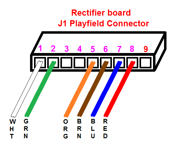
Looking at your new rectifier board picture with J1 connected, the brown and blue wires are still in the wrong positions. Did you move those wires yet?
The brown wire needs to move left one position from pin 7 to pin 6 (next to the orange wire) and the blue wire needs to be between the brown and red wires.

The brown wire is solenoid power (43 volts) to the playfield and you've got it connected the the 6 volt lamp output on the rectifier board - hence the solenoids aren't getting enough power.

RectifierBoard_J1_Playfield_Connector.gifRectifierBoard_J1_Playfield_Connector.gif

Quoted from Millennial-Pin:

Please also note that since I have owned this machine there has always been the jumper lead grounding on of the resistors (shown below).

Someone has hacked up that red alligator clip jumper wire to the transistor that drives the flipper enable relay, presume the flippers weren't working. The side effect is the flippers will work even when the game tilts or goes to game over. You should diagnose and repair the original problem.

#5 3 years ago

Quench!
Thank you for all your help you are truly a wiz. Solenoids power up but new issue no power to my digit displays, is this possibly related to my red wire on the J1?

#6 3 years ago

Check the F1 fuse on your SDB.

#7 3 years ago

The F1 on SDB tests okay. I’ve noticed that I’m not picking up the 230vdc on the power supply board at TP2 or on the J3 5th pin. Does anyone have a schematic of what my E# solder points should be reading?

image (resized).jpgimage (resized).jpg
#8 3 years ago
Quoted from Millennial-Pin:

Does anyone have a schematic of what my E# solder points should be reading?

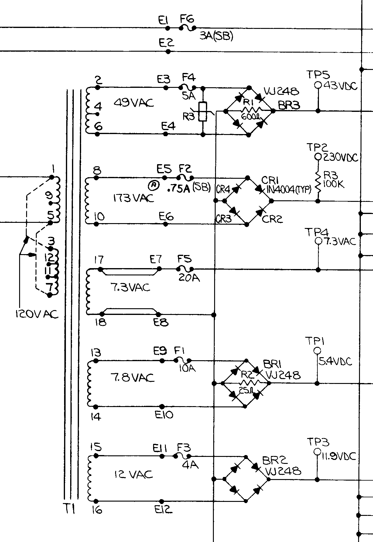
The E# voltages are listed in the original Bally schematics:
Note they are AC voltages at those points - set your multi-meter accordingly.
Also to measure those voltages you need to put the meter leads across the two points, i.e. not with respect to ground. So either meter lead goes on E5, the other meter lead goes on E6. Should measure in the vicinity of 173 volts AC.

RectifierBoard_TransformerPoints1.gifRectifierBoard_TransformerPoints1.gif

#9 3 years ago

Thanks everyone for your overwhelming support.
With the schematic I was able to verify that all E points are testing correctly. Issue traced back to a poorly connected fuse holder on the new board, now fixed. Now that the solenoids power up I have a new interesting issue.

When the three pop bumpers are triggered they all register points but they fire different solenoids. The top pop bumper activates the right saucer socket, the second pop bumper activates the bottom right bumper (above flipper) and the third pop bumper does not active any other solenoid but registers points.

It's also worth noting that other solenoids fire correctly when triggered.

Any ideas what would cause this?

#10 3 years ago

Issue Solved,
If anyone else is following my saga Quench was able to diagnose this for another Bally under the following thread:

https://pinside.com/pinball/forum/topic/bally-powerplay-fires-the-wrong-solenoids

Promoted items from Pinside Marketplace and Pinside Shops!
$ 44.99
Cabinet - Shooter Rods
Pinball Shark
 
$ 18.95
Eproms
Pinballrom
 
$ 12.00
Electronics
Yorktown Arcade Supply
 
$ 8.00
Electronics
Third Coast Pinball
 
$ 69.00
Gameroom - Decorations
Pinball Pimp
 
$ 10.95
Eproms
Pinballrom
 
2,000
Machine - For Sale
Franklin, VA
From: £ 22.00
Electronics
Retro Electro Designs
 
From: $ 1.25
Playfield - Other
Rocket City Pinball
 
$ 10.00
$ 69.00
Gameroom - Decorations
Pinball Pimp
 

Reply

Wanna join the discussion? Please sign in to reply to this topic.

Hey there! Welcome to Pinside!

Donate to Pinside

Great to see you're enjoying Pinside! Did you know Pinside is able to run without any 3rd-party banners or ads, thanks to the support from our visitors? Please consider a donation to Pinside and get anext to your username to show for it! Or better yet, subscribe to Pinside+!


This page was printed from https://pinside.com/pinball/forum/topic/bally-lost-world-solenoid-playfield-lights-power-issue?hl=quench and we tried optimising it for printing. Some page elements may have been deliberately hidden.

Scan the QR code on the left to jump to the URL this document was printed from.