 Piershil
Focus on the relay getting to work correctly.
That is way you don't see any voltage at the flipper buttons.
Check for continuity between SDB (A3)J4-8 and CPU (A4)J4-7.
This is the line which activates the relay.
(Topic ID: 85292)
 Ali
Stern Electronics, 1980
Baby Pac-Man
Bally, 1982
Big Game
Stern Electronics, 1980
Black Jack
Bally, 1978
Black Pyramid
Bally, 1984
BMX
Bally, 1982
Bobby Orr's Power Play
Bally, 1978
Catacomb
Stern Electronics, 1981
Ali
Stern Electronics, 1980
Baby Pac-Man
Bally, 1982
Big Game
Stern Electronics, 1980
Black Jack
Bally, 1978
Black Pyramid
Bally, 1984
BMX
Bally, 1982
Bobby Orr's Power Play
Bally, 1978
Catacomb
Stern Electronics, 1981You're currently viewing posts by Pinsider inkochnito.
Click here to go back to viewing the entire thread.
Quoted from JohnBillerman:Thanks inkochnito,
I verified continuity between SDB J4-8 and CPU J4-7 - also past the headers into the board.
The relay pulls in during solenoid test mode and when grounding Q15 (in attract mode only.)
Any next steps?
I believe the traces in the damaged area all buzzed out earlier, but maybe I'd better take another look down there.
If the relay works in solenoid test mode, it should be working during a game.
Quoted from Spitfiren8:Can anyone let me know if its safe to slave in a medusa mpu into my flash gordon for troubleshooting? Im trying to nail down a reset issue im having.
Yes, it is, but the rom chips (U2 & U6) must be the same type (like 2716 or 2516 or masked) for it to work without changing the jumpers.
Quoted from desertT1:I replaced this cap today and the game played at least 10 times and no resets. Thanks for the suggestion, seemed to be exactly what was needed.
Your board may also benefit from a upgrade.
http://www.pinwiki.com/wiki/index.php?title=Bally/Stern#Solenoid_Driver_Upgrades
Peter
www.inkochnito.nl
Quoted from statictrance:So I'm looking at the manual and can't find a switch matrix for the life of me. I know this era is a 5x8 array and am trying to pinpoint some odd behavior.
Anyone have any idea where to find the switch matrix for a strikes and spares online? Or is it as easy as writing down the switches in order (if so, is it 1, 2, 3 down the first column, or across the row?)
Also - any tips if you get a credit by wiggling a controlled lamp? (Not kidding... Figured I'd start with tracing the wire but had to ask)
Here is a copy of the switch matrix.
I've added the numbers per switch.
Also added some names for unnamed switches.
Peter
Bally_Strikes_and_Spares_SW-M (resized).jpgQuoted from Chalkey:Why did this dude add resistors to the digit drivers?
[quoted image]
What type of display is this?
The older Bally displays are missing resistors which are added in the newer type displays.
That may be why...
Peter
Quoted from MrSanRamon:Does anyone know where i can get a Bally Night Rider (SS) lamp matrix?
Robert
It is on my todo list for creating Tech Charts for Bally games.
Alass it is one of the last games to do, but for you I'll do it right away.
Here is a copy of the lamp chart.
Please notice some wire colors are marked in yellow.
The marked colors are the colors used in all the other games in this position.
The number behind the column is the color info taken from the manual.
You will have to verify which wire color is actualy used.
Please let me know and I'll change the list accordingly.
Peter
http://www.inkochnito.nl
Bally_Night_Rider_Lamp_Chart.pdfQuoted from jsa:I will check them, there are two of these (I believe a 9 and possibly a 14 or 20). I don’t believe the colors/positions are documented anywhere, so my best course is to check that colors continue through the connectors. If anyone can find it documented let me know.
Here is the page from the schematics...
Future_Spa_Plug_Connectors (resized).jpgQuoted from Aladdin:Tech Question:
Bally Evel Knievel
Feature Lights shut off once the game warms up
I then shut the game off and turned back on, and this time once the game warmed up, the Feature Lights froze?
Is this due to a Bridge Rectifier going bad?
I'm thinking I need to just rebuild the Power Supply Board and see where that takes me?
Inspect your lamp driver board.
Look for bad solder joints at the connectors and possibly acid damage from the MPU above it.
Check the ground connections at J4 (1-2 & 11-12).
Peter
Quoted from Robotworkshop:Question about the Bally and Stern Solienoid driver boards. It it my understanding that the regular Bally AS-2518 and Stern SDU-100 boards are interchangeable. Upon looking over a couple versions of the Bally board I noticed something odd on J3. On one of the Bally boards pins 18-24 are all tied together on the back of the board. On a different Bally board and the Stern board pins 23 and 24 are separate from pins 18-22.
I'd like to verify that there isn't a solder bridge on that first Bally board or if it is ok if the other boards should be bridged the same to tie grounds together at the board.
A3-18 thru 24 are all ground connections.
Yes, you can connect them.
On Stern SDU boards they kept the Solenoid ground seperately and maybe on some early Bally boards.
Also follow the instructions as layed out on www.pinwiki.com
http://www.pinwiki.com/wiki/index.php?title=Bally/Stern#Solenoid_Driver_Upgrades
Peter
http://www.inkochnito.nl
Quoted from Robotworkshop:Hello Peter,
I've added the extra jumpers on the board but the Wiki never mentioned tying the grounds on pins 23 and 24 to the others on 18-22 or that some versions already had those tied together. I guess if they should be then that would be good to update the Wiki. I didn't know there was a difference until I had a couple different versions of the board and thought one may have had a solder bridge.
Can you post some images of the board in question?
Maybe the type of board or markings on the board.
Quoted from Quench:Another difference between the two solenoid driver boards is that Bally fitted a 2.2 ohm resistor at R50, while Stern fitted a 4.7 ohm resistor which results in their 5V supply being a fraction higher (around 5.2 volts compared to Ballys 5.1 volts.).
Some Stern driver boards do not have a high voltage fuse.
Quoted from Robotworkshop:This Bally AS-2518-22 has the ground for pins 18 through 24 all tied together. This board has a fuse for the display power.
Since this looks like a newer board it seems that maybe the earlier boards could be updated the same way. Is anyone already combining the grounds like this on the earlier boards?
[quoted image][quoted image]
I would combine those grounds.
It is always better to have multiple ground wires.
I've done the same kind of upgrade to the Gottlieb System 80 driver board.
Works perfectly.
Quoted from Heaterguy:Thanks, I think LOL....Wierd stuff is happening, on game start the pop bumpers pop instead of chimes.
I soldered the jumper because I was not getting voltage and now solenoids fire but the pop bumpers are firing instead of the Chimes, the out hole and saucer do not fire (including when in self test) During self test when the Chimes should fire, the pop bumpers fire and one of the left lower slingshots fire. Same thing during game play. I'm certain the J plugs are connected correctly to the solenoid driver board I even verified the wire colors in the connectors and re pinned them. I have the correct game configured for the alltek mpu. I am going to do a memory clear and reset for strikes and Spares and see what that does.[quoted image]
I can see a problem with the print headers.
It's not unlikely that there are more pins bad.
Look at the red circle....
Backside_circle (resized).jpgQuoted from Heaterguy:Wow Thank you thank you thank you! Upon close inspection there are 3 other ones even worse. (Loose)
I did not even think to reflow the pins as I have not had to do that except for one other machine. Will definitely do that when I replace C 23. One more question I have is the smaller red Molex connector pins....are they .100 or .093 Size? I have .156 trifuricons and re pinned those already but need about 200 of the smaller ones and don’t have any, as I have not had to do these type before. Do they remove the same way as the .156 pins do?
The red molex connectors use the .100 pins.
Yes, the same way as the .156 pins.
Do the ground upgrades as mentioned in the Pinwiki.
They are really a MUST do.
Quoted from desertT1:The flippers died on my Stars on location. I’m getting power to the coils, but not to the cabinet buttons. When a game starts I don’t see/hear the relay power up. Q15 measures the same as other transistors, so I think that’s good. Check solder and reflowed headers anyway. What are the odds the relay actually went bad? Those tend to be pretty robust in my experience.
Do you have 43v at the relay?
You can check by measuring at the tab of Q15 or the testpoint.
Quoted from Robotworkshop:What is everyone setting the voltage to for the displays? Manual shows it should be 190v +-5v. I know on some of the older Williams you can drop the voltage a little to extend the life of the displays. Just wanted to see if others are doing that on the Bally/Stern machines too and if so what are you setting the voltage to?
170V is mostly used.
Hi Guys,
I have a Vector here for repairs.
The backbox was seperate from the cabinet.
The hinges were missing.
There were a pair of them in the spare parts box that came with it, but bolts to mount them.
Can anyone tell me which size bolts I would need for the hinges?
Peter
www.inkochnito.nl
Quoted from desertT1:Stern Stars is struggling to kick out a ball. The drops were struggling to reset as well. It’s as if the voltage dropped, but the flippers seem to be fine. Suggestions?
Check the bridge rectifiers.
Do the diode test on them.
Most likely one is bad.
Quoted from Mathazar:I then took a closer look at the J3 connector (specifically the jumper wire connecting pins 13 and 25). No continuity. I pulled the jumper wire out, and sure enough one of the pins that I had re-pinned months earlier was mangled. I re-pinned the jumper wire, put it back in, removed the TP1 to TP3 alligator clips, and everything works again with the Bally SDB.
The Alltek board apparently does not need that jumper wire present in the J3 connector. I screwed up the crimp months ago and never knew it because the Alltek board just worked. When the Bally SDB didn't work, I never suspected there to be a wire issue given that the Alltek worked fine!
[quoted image]
There is an upgrade you should do to the AS-2518-22 board.
Look here on the www.pinwiki.com:
http://www.pinwiki.com/wiki/index.php?title=Bally/Stern#Solenoid_Driver_Upgrades
Peter
Quoted from Chalkey:What's the easiest way to move a Bally LE cab? Removing the head and wrapping / strapping it to the body the same as a normal cab? The bottom section with the score displays stays put right?
I always take the head bolts out behind the displays, then turn the back box 180 degrees and tie it to the cabinet.
Peter
Quoted from Quench:The wire gauge is a similar thickness to the other factory jumper links on the board. Holes are 0.8mm drill diameter.
You can use component lead clippings similar gauge to the jumper links already on the board to do the job.
I do the same with the C26 and C23 capacitor ground mods although I use thicker gauge component lead clippings for the C23 mod because of higher C23 surge currents on power-up.
Picture please!!
I never though to do it that way...
Quoted from RobDutch:Can't start a game on my Lost World.
It does not boot for some reason (not a single flash) and the green led stays on.
All testpoints are getting their voltages and all ic sockets have been replaced and all connectors are cleaned. (It did not fix it)
Also the displays and insert lights stay off.
It's like the machine doesn't get told what to do; broken rom?
Anyone got a clue? Thanks in advance
[quoted image][quoted image]
Not a flash means no program to start.
So, yes rom problems.
Check your solder work again and wire the board to accept 2732 eproms.
Burn new eproms and try again.
Quoted from statictrance:Alright, have a controlled lamp driving me batty... I've done the following - any ideas?
1 - replaced socket. Can confirm clipping tab to a neighboring tab works.
2 - repinned connector. Twice.
3 - confirmed connection between socket and wire. Ran a brand new wire just to be safe
4 - replaced lamp board from another 100% working Bally game. Still that same one lamp out in game. (Conversely, other game is working 100% with the other board).
Seems it has to be above that - but given how it all works I can't believe the MPU wouldn't only misfire one single lamp. Any ideas of something I missed before I keep swapping and repinning?
Which lamp in which game?
Quoted from statictrance:Son of a bitch .. it had perfect continuity and everything, but I reflowed and there it is. I was leery of it being a reflow/transistor issue, that's why I just swapped boards. Very strange both worked just fine without any adjustment or modification in Mystic
Thank you Inkochnito... That's what I get for being in a rush
Lesson number one, always reflow the print headers when a board is out of the game.
Especialy if it is still original.
It solves 90% of the problems.
Quoted from JethroP:Can't understand how a bushing going out would cause a high pitch sound. It's not a squeak I hear...it's a high frequency electronic sounding pitch.
Isn't this the normal 10 point sound for the slingshots?
I remember the sound being odd when I had the game.
You can use a experimental board (breadboard?) for this.
Add print headers as input at one side to match either J1, J2 and/or J3.
Add a switch for each lamp you want to interrupt.
Add wires at the other end (exit) of the board and a matching connector for the one you used for input.
Another option is to use print headers too at the exit and have a connector interface cable with a connector at either end.
Quoted from djblouw:Thanks for the input.
Will hooking the lamp direct to ground cause any issues (if I wanted a lamp to always be on)? I know I could hook it up to GI, but that a different discussion.
It would not be a problem if you do it at the board I said.
You can use a 3 stages switch (left-middle-right) and use the middle as an off state, left always on, right regular working.
Connect a ground to the left and the right going to the original A5 lampdriver board.
This might be helpfull:
http://www.pinballrebel.com/pinball/cards/Tech_Charts/Bally_Eight_Ball_Deluxe_Tech_Chart.pdf
Check out my website for Tech Charts on Future Spa and Dolly Parton.
You can find them both in the Bally section and in the Tech Charts section.
http://www.inkochnito.nl
Quoted from guitarded:Thanks Inko, that's super handy to have!
So it looks like I need replcements for 2N5060 in each of those positions. Anything else I should change along with them?
Reflow the pins on the lamp driver board.
It solves 90% of the problems.
Sometimes acid damage is present on the top or bottom traces.
This is my test cabinet....
An old Xenon machine.
Cabinet was destroid by water, playfield bare to the wood all the way.
Playfield parts used in other Xenon games.
Backglass very bad.
Only the boards, wires and lamps could be used.
I even got a special test eprom in co-operation with Scott Charles.
To test the displays, lamp driver boards and solenoid boards with a single eprom in U6.
Peter
20190917_212801a (resized).jpg20190917_212834a (resized).jpg20190917_213022a (resized).jpgQuoted from Robotworkshop:Is that test ROM available?
Yes, it is available. (version 8 actualy)
I've been using the test file for some time now.
It serves it's purpose perfectly.
I've asked Scot: "Do you mind if I share this file with other people?"
His reply was: "Nope, go ahead. It was written to be used."
So here is a download link for the file:
https://drive.google.com/open?id=1YhCmR23TABQAUylleguAHQiZQOx-g3_L
Instructions are in the txt file within the zip.
Peter
Quoted from matiou:Question about the rectifier board...... When the machine is off, playfield and backbox harnesses disconnected from the rectifier board, should I get continuity between the GND test point of the rectifier board and the metal plate underneath ? Because I don't......
Nope, I don't think so.
There in nothing to connect to via the rectifier board.
It's mounted on plastic stand-offs and the bridge rectifiers are not conductive to the outer casing.
Game: Bally - Rolling Stones.
How can it be that one switch line in the switch matrix is very sensitive to the touch?
I mean, if I hold the ground (side of the cabinet) and you touch the I5 line, the lower pop bumper gets activated.
Not just a single puls, but it can even hold it down.
The background sound also change.
At one point it gives irratic behaviour of the lower pop bumper even when not touched.
I know this kind of behaviour is typical to Bally games at some point.
I just want to know why this happens and why only at the I5 line and not any other.
I removed the switch caps at the pop bumper switches, which caused bad/slow behaviour of the pop bumpers.
Quoted from Quench:Find return lines I3 to I7 under the playfield, what happens when you body ground them and observe the fast react solenoids on those switch return lines? I think you'll find they do the same thing, i.e. it's not just I5.
You are correct.
I've tested this and it works extra sensitive on targets when thouched at the junction of the diode and capacitor.
I suppose that the best way is to replace the caps with brand new ones (not 30 year old ones) to avoid irratic behaviour. ![]()
Quoted from vec-tor:Bally playfield switch wiring Note:
Bally switched wire color sequences on ST1 and ST2.
From MPU A4J2.
1) Old Bally Switch wire color code:
ST0 [ 51 ]
ST1 [ 93 ]
ST2 [ 52 ]
ST3 [ 53 ]
ST4 [ 31 ]
up to Bally Hotdoggin / Viking.
--------------------------------
Starting with Skateball
2) New Bally Switch wire color code:
ST0 [ 51 ]
ST1 [ 70 ]
ST2 [ 93 ]
ST3 [ 53 ]
ST4 [ 31 ]
--
Also "L" target bracket changed from just two holes to
one of the holes being more oblong adjustable.
Correct you are.
I noticed this too when creating the Tech Charts.
Quoted from Nokoro:Every single bulb in my game appears to be out.
This will also happen when resistor R2 (25 ohm) on the rectifier board breaks or gets loose.
That will surge the 6.5VDC and burnout all the switched illumination bulbs.
I've seen it happen twice already.
The general illumination will keep on working just fine, because it is a seperate circuit.
Quoted from Nokoro:Interesting. Thanks for the tip.
R2 looks intact on my board and measures 25 ohms as it should.
As I mentioned, connector J1 was misconnected and off by one pin. I wonder whether that could have caused this.
It is very well possible.
It could be that the solenoid power (bus) was on the switched illumination power (bus).
Option B would blow all the switched lamps possibly.
Option A would blow all the general illumination lamps.
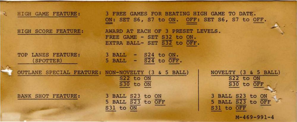
Quoted from RoyGBev:Yeah didn't notice about the knocker. Couldn't the head also be 6M$M, Voltan(!), Kiss, Harlem or Dolly?
I tried to match the text on the adjustment cards stapled in the backbox with pics from ipdb. It does look like the Eight Ball cards but I'm not sure.
What are the numbers in the lower right corner of the cards/labels in the backbox?
For Eightball it should be M-469-991-4 for example.
http://www.pinballrebel.com/pinball/cards/cards/Used_cards/Bally_Eight_Ball_M-469-991-4_Recommended_settings.jpg
Quoted from desertT1:Player 2, 4, and the ball/credit display were connected. When removed so no displays were connected there are still crackly sparks.[quoted image][quoted image]
Your High Voltage section is broken.
Atleast one, but most likely more, transistors are broken.
The resistor which is burned tells me this.
Time to rebuild the HV section.
Also check the transformer (fuse) board for bad diodes.
Replace the connector pins at A3J3 and the print header.
While you have the board out, also replace the old caps on the board.
And do the ground upgrade.
Quoted from hisokajp:I assume he meant that one:
https://www.pinwiki.com/wiki/index.php?title=Bally/Stern#Solenoid_Driver_Upgrades
Yes, you are correct.
http://www.pinwiki.com is your number one stop for information.
Quoted from Nokoro:I have an old MPU and SDB from a game I acquired. Both boards were swapped out by the prior owner. I'm not sure if either board works. There appears to have been a thermal event above the area where the SDB sits in the backbox. As for the MPU, I'm not an expert, but it appears as if there is some battery leakage. The board smells a bit acidic and is a bit sticky with some areas of corrosion showing.
My question is whether there are parts worth salvaging on either of these. I don't have the skills to fully diagnose and repair, especially with acid damage. Are the socketed chips at least worth removing and keeping? Anything else? Or, would the boards be worth anything in the condition that they are in?
[quoted image]
[quoted image]
I've seen worst boards, but these are repairable.
Quoted from Phesson:Thank you Arari_Daze
Anything you can't find, just ask. ![]()
http://www.inkochnito.nl
Quoted from barakandl:This is an issue with the cheap squeak sound board. Exacerbated by MPUs with longer reset widths.
When the cheap squeak comes out of reset it programs the 6803 processor mode. The pins that program the 6803 mode also happen to be solenoid signals and forces the bit pattern for the outhole. The PIA ports are in Z state during reset making it easy for the cheap squeak to drive those signals, even through the series resistors to the solenoid decoder.
There is potential coil melting problem here. If the MPU and Cheap Squeak are below the 5v power monitor level and stuck in reset, the mode programming diodes on the cheap squeak can lock on a coil. If the cheap squeak and mpu had a reset buttons, if you held them both down, the outhole would lock on until the fuse blows or worse.
I fixed this on the replacement cheap squeak I make. I put in series resistors and a buffer chip between the solenoid signals and the 6803 processor. That way the mode programming will not be able to force the solenoid pattern for the outhole while in reset. All other bally sound boards have a buffer chip on the solenoid input signals. I think the "cheap" part left out that circuit and they decided to just live with the potential coil pulse at power on.
[quoted image]
You should add this information to the Pinwiki page.
Quoted from Phesson:I have a Mata Hari that has all modern boards. It has a problem that I noticed recently. During a 4 player game it will reset. It will play a 1,2 or 3 player game without incident but each time a 4 player game is played, it will reboot.
It is my understanding that most reset issues come from the 5 volt to the mpu dipping. I’m not sure why this would be isolated to a 4 player game.
Any leads on where I would start troubleshooting this issue?
My guess would be problems with the ram memory.
The game wants to write at the player 4 location, but for some reason it can't and causes a reset.
Try another ram chip (or nvram).
Quoted from jibmums:I just replaced the LM3900 amplifier in the second Space Invaders sound board, and I have volume again, so that fixes that problem. Still getting the same hum as the first board though, so I also recapped the second, and the damn hum is still there. I get the same hum whether the boards are screwed in tight or floating, which I see was a solution for some owners. Not sure what else I could try.
Did you replace the big capacitor on the solenoid/voltage regulator board?
That's where the 12V comes from.
Allthough the C15 on the the sound board should be able to compensate for this.
Quoted from jibmums:I assume that grounding the - of C13 to the backbox ground braid with an alligator clipped wire that I had handy would do the same thing, so I tried that. Not only didn't it lower or eliminate the hum during a game, but it introduced a new hum, fairly low but still there, during attract mode.
Oke, so don't do that.
Bad idea then....
Well, it was just a thought anyway.
Quoted from jibmums:Wouldn't I get a hum as soon as the game is switched on then? Hum only begins when I start a game. You can hear it over the "dum-dum-dum-dum" background noise, but when a sound effect plays it momentarily stops, then begins again right after the sound effect stops.
Did you move any of the chips from one board to the other when testing?
Sometimes the AY-3-8910 goes bad, but still creates (wroung) sounds.
The eprom can also be bad or missing some bits, but then the board wouldn't start.
Quoted from jibmums:Nope, just new caps on both, and new LM3900 amp on one. Both sound boards should be exactly the same now, so I'm guessing the problem has nothing to do with either.
I've tested 6 different sound boards with a Space Invaders eprom in my test rig.
All have the same hum you mention.
Present when "dum-dum-dum-dum" background noise is played, but when a sound effect plays it momentarily stops, then begins again right after the sound effect stops.
I think it has someting to do with the programming.
Maybe something that needs to be sorted as being a bug in the system.
The same boards with another eprom (Rolling Stones) do not have this hum.
Quoted from Grefla:or perhaps I could use this
https://www.ezsbc.com/product/psu5-nonoise/
Does anyone have any opinions on this product?
Good product.
You must make some small corrections to the board, as to change some parts.
https://www.pinwiki.com/wiki/index.php?title=Bally/Stern#Driver_Board_LM323K_5V_Regulator
Peter
Quoted from gdonovan:Has Bally Stamped ESBM 8xxx serial number on head in correct location, size and font.
ESBM = Electronic Silver Ball Mania
Or be done with the LM323 and use a PSU5 part.
https://www.ezsbc.com/product/psu5-nonoise/
There are some adjustment/replacements to be done to make this work correctly.
Read this:
https://www.pinwiki.com/wiki/index.php/Bally/Stern#Driver_Board_LM323K_5V_Regulator
Quoted from kmart00:The Tech Charts at pinballrebel.com are incorrect for early Bally SS (-17 MPU) machines. For these chime games, they list boards more commonly found on games with electronic sound (-35 MPU).
My Eight Ball still has its AS-2815-14 Lamp Driver and AS-2815-16 Solenoid Driver boards. They work just fine.
[quoted image]
Hmm, I think I overlooked this as I did change the MPU number.
All the files for the MPU-17 are adjusted now.
It would have been nice if you had send me a PM or email. ![]()
Luckily I do a regular check of this club.
Peter
http:www.inkochnito.nl
If you like my work, please send me a donation via PayPal.
Quoted from Shapeshifter:I was able to check fuses, tilt switch, and coin door.
No flashes, just the GI lights come on.
There is a very loud buzzing when the connector/wires are moved - bottom left in photo. J2.
Maybe just a different fault, not sure.
It will be a while before we go through the Pinwiki voltages though.
Thanks for the suggestions.
[quoted image]
Check the knocker and the coin lockout (both are on J2).
The knocker is in the cabinet and the coin lockout on the coin door.
Most of the time it is the coin lockout that is buzzing.
Peter
www.inkochnito.nl
Quoted from mad_carl:working my way through some issues on a Rolling Stones and I found a clipped yellow wire on the memory coils for the 4 bank drop targets. I didn't even realize this game had them until I found the wire.
Anyway I re-soldered it, and now the coil locks on at power up. Obviously why it was clipped. It's pretty toasty. And it's just that 1 coil of the 4 of them where the power comes in.
Maybe I'm blind but I can't find the memory coils in the schematics online. I check all the transistors on the SDB, and they all read similar so I couldn't pin point it. Am I missing something?
Check my Tech Chart for Rolling Stones.
https://www.pinballrebel.com/pinball/cards/Tech_Charts/Bally_Rolling_Stones_Tech_Chart.pdf
Peter
http://www.inkochnito.nl
You're currently viewing posts by Pinsider inkochnito.
Click here to go back to viewing the entire thread.
Wanna join the discussion? Please sign in to reply to this topic.

Great to see you're enjoying Pinside! Did you know Pinside is able to run without any 3rd-party banners or ads, thanks to the support from our visitors? Please consider a donation to Pinside and get anext to your username to show for it! Or better yet, subscribe to Pinside+!

This page was printed from https://pinside.com/pinball/forum/topic/bally-as-2518-club?tu=inkochnito and we tried optimising it for printing. Some page elements may have been deliberately hidden.
Scan the QR code on the left to jump to the URL this document was printed from.

 Reno, NV