(Topic ID: 85292)

Bally/Stern AS-2518 Club !

By mof

10 years ago


Topic Heartbeat

Topic Stats

  • 3,895 posts
  • 369 Pinsiders participating
  • Latest reply 29 hours ago by Trainmonger
  • Topic is favorited by 287 Pinsiders

You

Linked Games

Topic Gallery

View topic image gallery

20231120_185916.jpg
pasted_image (resized).png
20240408_190857.jpg
20240408_190920.jpg
20240408_190853.jpg
IMG_2447 (resized).png
IMG_2446 (resized).png
IMG_1013 (resized).jpeg
IMG_1804 (resized).jpeg
IMG_1847 (resized).jpeg
IMG_1849 (resized).jpeg
IMG_1856 (resized).jpeg
IMG_2083 (resized).jpeg
IMG_2088 (resized).jpeg

You're currently viewing posts by Pinsider Quench.
Click here to go back to viewing the entire thread.

#802 6 years ago
Quoted from vec-tor:

I like it! I only wish you had a spot to add another 6821 PIA and piggyback
breadboard experiment area.
( need more dipswitch options ) (need a few more switch strobe lines) Great job.

With the amount of available ROM/NVRAM space now, just implement "software settings" instead of requiring more dip-switches.
How many total playfield switches do you need? Can you get away with using more unused continuous solenoid data lines as switch strobe lines ala Fathom/Medusa - etc? The coin lockout coil data line could also be re-purposed as another switch strobe line.

#807 6 years ago
Quoted from Coyote:

On the -23 Lamp Board, can someone explain to me what R70 is used for? It *appears* to only feed the test point?

Test point TP3 that's connected to pull-up resistor R70 on the Lamp Driver Board is there for manually testing SCRs. Connecting a wire from TP3 to the gate lead of any SCR should activate the respective lamp.
It's mentioned as part of the Lamp Board diagnostic procedure in the Bally Repair Procedures manual FO-560

There are also pull-up resistors connecting to test points only on the SDB that are used for similar purposes.

2 months later
#863 6 years ago
Quoted from Robotworkshop:

If I'm not mistaken the 2K chip at U6 is the main operating code (same for several machines) and the 2K chip in U2 is the game specific ROM.

Correct.

Quoted from Robotworkshop:

Does anyone happen to have the memory map of the AS-2518-17 MPU board?

$0000-007F 6810 RAM
$0088-008B 6821 PIA U10
$0090-0093 6821 PIA U11
$0200-02FF 5101 RAM (upper 4 bits only! - ROMs expect lower 4 bits to read high)

$1000-17FF U2 ROM
$1800-1FFF U6 ROM

Address lines A15, A14 and A13 are not used on the MPU board itself which means the above memory map gets mirrored all over the place. Suffice to say U6 is mirrored at $F800-FFFF in order for the 6800 CPU to read the system vectors.

Quoted from Robotworkshop:

PinWiki where U2 may be at $5000-$57FF and U6 at $5800-$5FFF

The $5xxx range is related to -35 boards, not -17 boards.

Have you already come up with some alternate rule/feature plans?

#866 6 years ago
Quoted from Robotworkshop:

What I would like to see happen is if the dealer wins you should either get no points or you should lose points as those go back to the dealer. I think you should lose as many points as you'd win if beating the dealer. As a stretch maybe play a different tune if the dealer wins.

Great ideas..
I can give you pointers of where to start looking. PM me if interested.

1 month later
#905 6 years ago
Quoted from wylcot:

The MPU seems to boot correctly (2 flashes, one second, and then 5 others...) but nothing after that.
Nothing from the displays or the solenoids...

I think you might be incorrectly counting the LED flashes.

Count the flashes on the Skateball next to it and you might notice an extra flash. Both MPU boards should flash the same number of times.

The moment you switch on the game, the LED should flicker, then flash one time, then one second delay then 6 flashes. If you're seeing 5 flashes instead of 6 flashes after the one second delay the problem is most likely the F4 5amp fuse on the rectifier board is blown.

Quoted from wylcot:

Are the boards from 2518-17 and 2518-35 compatible? Can I try the Skateball ones on the EK to exclude things??

The -17 and -35 MPU boards are not directly interchangeable without making modifications.

#909 6 years ago
Quoted from wylcot:

ok, so definitely the F5 fuse on the rectifier board, then...

That F4 fuse looks blown. It's for solenoid power and is required by the MPU board for the last LED flash.

Quoted from wylcot:

Definitely where I'll be looking at when I go to his place...

Absolutely. Someone has improvised and made a discrete rectifier with those 4 diodes but they don't look like they're high enough current type diodes.

#932 6 years ago
Quoted from wylcot:

Anyone can help me with the values of this bridge rectifier, please?
The documentation says VJ248 VARO ... ?????? Can't figure out what this is...

I use these that directly fit in:
KBPC810PBF made by Vishay Semiconductors.
http://export.rsdelivers.com/productlist/search?query=KBPC810
https://www.mouser.com/Search/Refine.aspx?Keyword=KBPC810

Be careful of the cheap Chinese units on Ebay/Aliexpress - they are physically bigger and won't fit.

1 week later
#942 5 years ago
Quoted from Schwaggs:

The parts you linked are 8A bridges. I thought the stock bridges were 10A.

Yes, my response was a bit lazy.

The controlled feature lamp bridge is where it might matter since it runs at high current (the other two bridges are lower current circuits). You can swap one of the other VJ248 bridges to the lamp bridge location if it's a concern and use the KBPC810 bridge in the lower current locations.

Keeping the bridges cool helps them survive during heavier loads. I use a good quality thermal paste between the bridges and the aluminum/metal plate, and make sure all three bridges are screwed down (no missing screws as you sometimes find).

2 weeks later
#957 5 years ago
Quoted from barakandl:

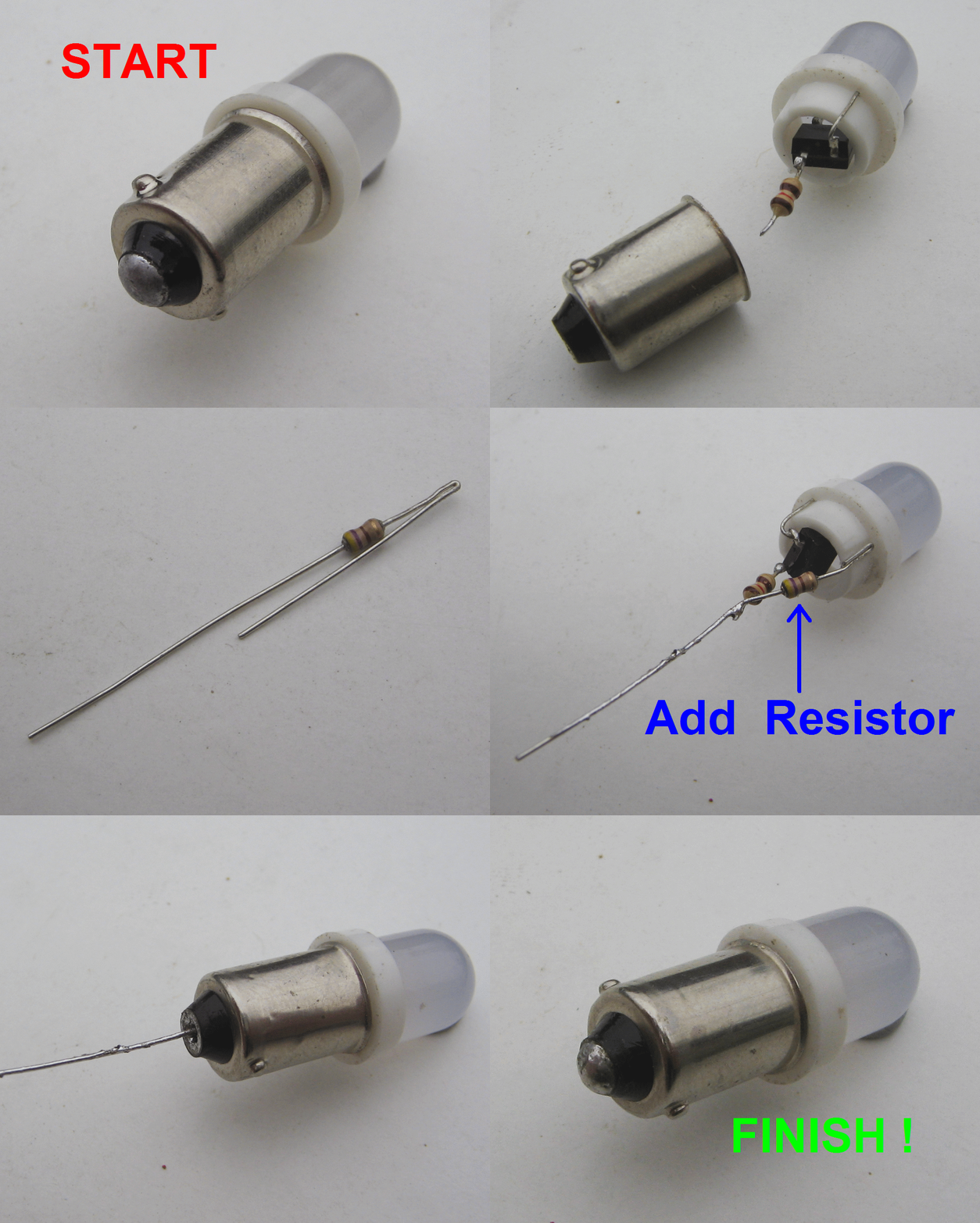
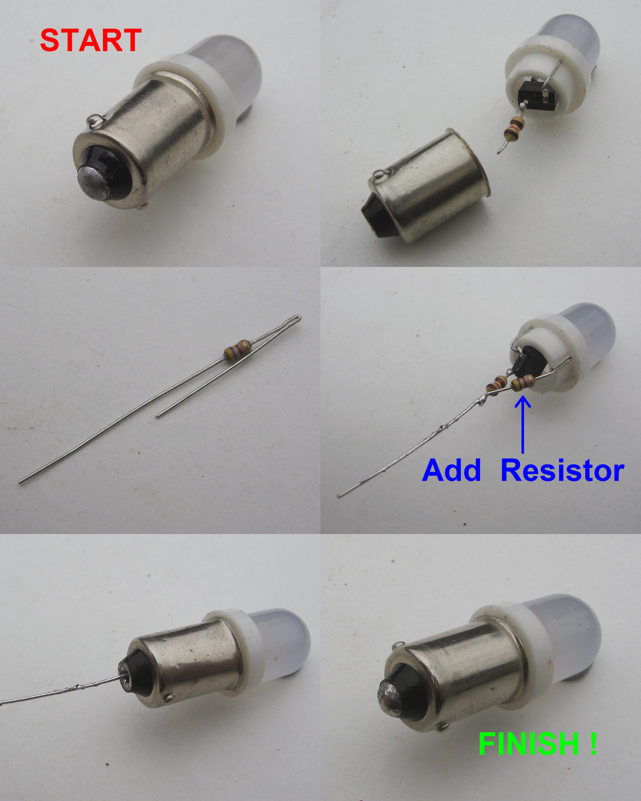
I am surprised LED bulb sellers/suppliers haven't put a $0.003 resistor across the leads of the pinball LED lamps to create and sell a "bally" line of LED bulbs.

A year or two ago I tried to get ADT to make me some for personal use and I tried to convince them there is a market for these. But they didn't seem overly interested. I sent them the attached slideshow. MOQ per color/type was 1000 pieces but they wouldn't make me any samples to ensure they were going to get it right first time. In the end I just modified some myself. Problem is some LEDs are full of glue in the bayonet and aren't possible to pull apart without damaging them.

output_8xk02S.gifoutput_8xk02S.gif

#965 5 years ago
Quoted from mrm_4:

Brilliant! I wish I saw this before I soldered about 40 sockets.

I saw you post that picture somewhere else and really liked the neat way you mounted that load resistor - so much so that I'll probably be employing your technique on a friends machine, thanks!

1 month later
#1066 5 years ago
Quoted from statictrance:

Anyone know the screw size to secure boards to the back of offhand?

#8-32 thread, thread length about 3/8"

1 week later
#1079 5 years ago
Quoted from statictrance:

I found that tying together TP1 and TP3 totally resolved my problem (TP3 was dead)

TP3 is connected to TP1 via an external wire on the solenoid driver board J3 connector. See below schematic.
Your fault was probably on the connector and you've essentially bypassed it.
TP3 is the 5V power test point of the solenoid logic driver side.

SDB_TP3.jpgSDB_TP3.jpg

#1082 5 years ago
Quoted from statictrance:

I hit the left sling with the ball and caused it to machine gun a bit. I quickly turned the power off (maybe 5 seconds?) and then was dead in the water again until tying those points together.

You mean the game wouldn't boot? If yes, you've got other problems unrelated to TP3.
No voltage at TP3 on the SDB will only cause solenoids not to work.

2 months later
#1239 5 years ago
Quoted from jsa:

However, those specific lamps I mention above, they will pulse with either LEDs or incandescents.

Since the auxiliary lamp board shares most of the lamp address/data lines with the main lamp board are any of its lamps flickering?
You haven't accidentally crossed the two lamp strobe wires at the MPU board connector or accidentally swapped a lamp address/data wire?

If you do swap the two lamp strobes at the MPU board connector do the flickering lamps follow the strobe line or stay with the lamp board?

#1242 5 years ago
Quoted from pinfixer:

(the MPU generates two strobes, 180 degrees opposite from each other)

Umm, no. The lamps on the second strobe are activated directly after all the lamps on the first strobe have been processed.

#1245 5 years ago
Quoted from jsa:

I'm happy to try that, I guess I need to figure out what is the Aux Lamp Board specific strobe wire, as it's not clear on the schematics.

Strobe #1 from the MPU board is at J1 pin 11 - goes to the main lamp board
Strobe #2 from the MPU board is at J1 pin 8 - goes to the aux lamp board

You can try swapping those two strobe wires around on that MPU J1 connector and see what happens.

Quoted from jsa:

I'm actually using a @barakandl new rectifier board. I know the test pads all test perfectly on that board, but that's the limits of my testing.

If TP2 on the Alltek MPU board reads 43V then the bridge rectifier for solenoid power (zero crossing) should be ok. If it read half voltage then the bridge rectifier would be suspect (internal diode open circuit).

#1247 5 years ago

The data lines to the lamp boards also go to all the displays. Have you disconnected all displays to eliminate any effect they might be having on those data lines?

#1254 5 years ago

Have you disconnected the Auxiliary lamp board as a test?

#1256 5 years ago
Quoted from jsa:

@quench if you wanted to see frequency and voltage readings from anything in this chain right now, what would you look for? I’m also going to inspect the zero crossing waveform this afternoon.

Hi,
Can you post a video showing the whole playfield (both in attract mode and lamp test mode) so we can see all the feature lamps that are flickering. Please remove the fuse for the GI lamps when you do this - the LEDs in your GI are causing heavy strobing making it hard to see what's going on.
We need to try and build a full picture to see if there's a pattern.

The 22.5VDC you measured at the Zero Crossing TP6 test point on the MPU board indicates it's unlikely to be your problem. An issue here should have resulted in a much lower voltage. To confirm, measure TP2 on the Alltek MPU board - it should be around 43VDC. The Alltek MPU board divides the voltage at TP2 in half which is where TP6 is connected.

If you want to hook up your oscilloscope to visualise it, set the voltage scale on your oscilloscope to something like 10V/division and the time scale to something like 2ms/division.
Hook up the black lead to ground and the probe tip to TP2 at the MPU board.
You should see a signal that looks something like the lower "Output Voltage" waveform in the image pinfixer posted here:

https://pinside.com/pinball/forum/topic/bally-as-2518-club/page/24#post-4607509

Adjust the voltage and time scales until you can see a good overall view of the waveform. Post a picture of it.

#1264 5 years ago

Your videos show the first 4 outputs of each of the lamp decoders (4514 chips on the LDBs) are flashing. Logic wise it's not a data/address thing, more likely timing.

Your first two oscilloscope readings look fine (time wise) - the periods of those waveforms are around 8.3ms (the time in which they repeat) which translates to a frequency of 120Hz and is right. Does your oscilloscope probe have a "X1 / X10" switch? If yes, put the switch on X10 which basically divides the input voltage by 10. You'll then be able to see the full height of the DC waveform at TP2.

Anyway, as barakandl has mentioned, the zero crossing detector circuit on your Alltek is outputting the wrong frequency (presuming you've probed the correct pin - U12 pin6). It should be the same frequency as TP2 and TP6. The wave shape will look different but the time taken to repeat should be identical.

Have you got a working Bally MPU board you can hookup?

#1266 5 years ago
Quoted from jsa:

also I have a working Bally MPU.

The Zero Crossing detector circuit output to probe on the Bally MPU board is pin 4 of U14.

BTW, I think you mentioned somewhere that before the game restoration there was no issue with the lamps. Exactly what's changed (hardware wise)?

#1269 5 years ago

Did you build the rectifier board or was it one barakandl pre-built?

Lets strip this down to bare minimum.
Completely disconnect the playfield from the game - I mean every playfield connector.
Disconnect any connectors to the display/lamp hinged panel in the head box.
Measure the voltage on TP1 of the rectifier board and if it's around the 6.5VDC range, grab a spare lamp socket and connect the base to that TP1. Connect the other end of the lamp socket to pin 18 of J1 header at the lamp driver board (remember the lamp driver board pins are numbered upside down from 1 at the bottom and count upwards). Pin 18 of J1 is the output for the centre target "S" lamp that's currently flickering. Power on the game and go to lamp test mode. Does this lamp still flicker with an incandescent and LED?

#1271 5 years ago
Quoted from jsa:

Wait, I'm getting 8.22vdc. Should I continue this experiment?

With no load it will be a bit higher, so no big deal.
But can you first hook up the oscilloscope to TP1 on the rectifier board and post the waveform. Adjust the volts/division on your oscilloscope so you get all the amplitude from the waveform to fit in the image - start from around 2 volts per division.

#1275 5 years ago

Ok, new waveforms look better About what's expected for a rectified DC voltage.
Can you confirm the 27 ohm ceramic resistor on the rectifier board is getting warm?

I know you've triple checked your connectors but can you post clear pictures of them at the following so we can see wire colors:
LDB J4
MPU J1
Aux lamp board connector J1

#1277 5 years ago
Quoted from jsa:

Getting warm is an understatement, it just burnt my finger.

Sorry

While I check your wires can you do the following:
Lets manually activate the SCR driving that temporary lamp you've connected to the target "S" lamp connection.
Grab a jumper wire and hook up one end to TP3 on the LDB. Touch the other end of the wire on the "gate" leg of SCR Q14. This will manually illuminate that lamp. With the Bally lamp driver board you've got, the gate leg on the small SCRs is the middle leg going upwards.

#1280 5 years ago
Quoted from jsa:

The light stays on SOLID.

Good. We can put to bed any issues with power and rectifier board.

Wire colors at the connectors look right which I'm sure doesn't surprise you.
At this point we have to check continuity from the MPU board to the lamp driver board *after* the connectors.
With the machine OFF, grab your multimeter and set it to resistance mode. If your meter is a cheap non auto-ranging unit, set it to 200 ohms range.
Check for zero ohms resistance between the following:

MPU left leg of R55 (next to J1 pin 15) <---> LDB top leg of resistor R76
MPU left leg of R53 (next to J1 pin 14) <---> LDB top leg of resistor R77
MPU left leg of R51 (next to J1 pin 13) <---> LDB top leg of resistor R78
MPU left leg of R49 (next to J1 pin 12) <---> LDB top leg of resistor R79
MPU left leg of R57 (next to J1 pin 16) <---> LDB bottom leg of resistor R74
MPU left leg of R60 (next to J1 pin 17) <---> LDB top leg of resistor R73
MPU left leg of R62 (next to J1 pin 18) <---> LDB top leg of resistor R72
MPU left leg of R65 (next to J1 pin 19) <---> LDB top leg of resistor R71
MPU left leg of R47 (next to J1 pin 11) <---> LDB top leg of resistor R75

#1282 5 years ago

Yep, ohms uses the omega symbol.

You also have zero ohms between the bottom left leg of SCR Q14 on the LDB and the rectifier board under the big ceramic resistor at the solder tab marked "E8"? This is checking that the lamp driver board has good ground.

#1295 5 years ago

While we work on this, please only use incandescents in the problematic lamps.

Some waveforms in Lamp Test mode on SCR Q14: These are steady while the lamp is on or off as noted.
My game is a 10 amp feature lamp game opposed to your 20 amp game, hence my lamp voltages are lower.
Do any of yours differ? Are your waves steady while the lamp is ON?

IMG_0021a (resized).jpgIMG_0021a (resized).jpg
IMG_0017a (resized).jpgIMG_0017a (resized).jpg
IMG_0019a (resized).jpgIMG_0019a (resized).jpg

#1297 5 years ago

Hi, sorry I should have mentioned all three snapshots I took were with 2ms/division time base.
You're getting negative voltages and lots of noise which suggests the earth lead on your oscilloscope probe isn't connected to ground on the machine.
BTW, set your voltage offset to "0V". I've positioned my waveforms so zero volts is at the bottom of the screen. Lets just leave yours with zero volts along the centre of your graph.

#1298 5 years ago

SCR Q14 bottom right leg image when the lamp is off should look the same as your second image from post #1274 (with the per division settings). And this is very close to mine.

FutureSpa_FeatureLampVoltage (resized).pngFutureSpa_FeatureLampVoltage (resized).png

#1301 5 years ago
Quoted from jsa:

Are your playfield lamps connected to the LDB when you do the recording?

Yes, I've walked up to my working machine with the oscilloscope and taken the snapshots with the game as is in lamp test mode.

Any chance you can do the Q14 gate leg with the same time base you used in the second image in post #1299 so we can see more repetitions?

That second image looks like the lamp is only being switched on once every three or so Zero Crossings. It should pretty much be once *every* Zero Crossing.

Can you do the same on Q11 which is a working lamp so we can compare?

Sorry to leave you hanging but I've got to head out - maybe someone else will chime in with your further results.

#1312 5 years ago
Quoted from jsa:

WHAT DOES THIS MEAN? Me monkeying with gate legs fixed it for a few seconds!?!?!?

What were your hands touching when this happened?
Does wiggling the J4 connector at the LDB change anything?

You can see from the snapshots of the gate pin playing up that the decoder tries to switch the gate on (where you see those skinny spikes) but for some reason cancels/fails before the SCR gate has reached switch on voltage.

Are you getting good 5V power and ground to the LDB through the J4 connector?

BTW, is it worth taking this discussion back to your restoration thread so things can return to normal here?

4 weeks later
#1338 5 years ago
Quoted from Chalkey:

Shame cuz it seems like it would be a small code modification.

It's not so trivial, the Bally operating system can only process one switch at a time so while the ball is sitting in the saucer, no other switches can be dealt with. All that can happen during that time is other switches can be flagged as needing to be serviced but there's no count facility for how many times they needs to be processed.

#1340 5 years ago
Quoted from Chalkey:

But it seems to work with the left spinner going when it lands in the saucer is that not the case?

That's not what I'm seeing in emulation. The bonus jingle being played while the ball in the globe saucer is taking precedence over servicing all the spinners.

1 week later
#1351 5 years ago
Quoted from Robotworkshop:

Does anyone happen to have a part number or link to the correct flipper relay on the Bally/Stern driver board?

https://www.greatplainselectronics.com/proddetail.asp?prod=LB2-48DP

#1356 5 years ago
Quoted from Robotworkshop:

Question about the Bally and Stern Solienoid driver boards.

Another difference between the two solenoid driver boards is that Bally fitted a 2.2 ohm resistor at R50, while Stern fitted a 4.7 ohm resistor which results in their 5V supply being a fraction higher (around 5.2 volts compared to Ballys 5.1 volts.).

2 weeks later
#1378 5 years ago
Quoted from Heaterguy:

Any other thoughts?
I am getting 44 volts to coils.

Measure the voltage at TP3 on the solenoid driver board. If you don't measure 5 volts then re-terminate the brown-green wire that runs between pins 13 and 25 at connector J3 or just solder a wire from TP1 to TP3 on the back of the solenoid driver board.

#1387 5 years ago
Quoted from Heaterguy:

now solenoids fire but the pop bumpers are firing instead of the Chimes...

As everyone said, you've got a connector issue on the signals between the MPU board and the Solenoid Driver Board (SDB) that indicate which solenoids to activate.
I don't have facebook so can't see your video but from your first description, the signal with issue is the red-white wire between MPU J4 pin 1 and SDB J4 pin 3. You should just re-terminate all wires on those connectors though.

#1389 5 years ago
Quoted from Heaterguy:

I scraped the red white wire on pin 1 of j4 and now it is not miss triggering however the chime still doesnt work

Exactly which solenoids are not working in solenoid test mode - are any still activating at the wrong time?

#1391 5 years ago
Quoted from Heaterguy:

I'm pretty happy though because I saved this machine from the scrap Heap convinced the cellar not to part it out bought it for $100

Glad you're saving this ol' girl. Keep at it! Sounds like the terminals at the MPU J4 connector got hit with battery corrosion from the original MPU board.

#1395 5 years ago

Good eyes Inkochnito ^^^
Inspect the soldering on the other pin headers in case more need to be resoldered.

1 week later
3 weeks later
#1437 5 years ago
Quoted from Pinhead306:

if I was to replace them with 7 digit displays do I need to do anything else so the game knows to count to a million or does it just know to to it?

As is, Harlem Globe Trotters has no concept of millions scoring. So upgrading to simple 7 digit displays requires mods.
There's a seven digit scoring mod here:

http://www.pinball4you.ch/okaegi/pro_soft.html

It requires a ROM upgrade to support millions scoring plus and a bit of hardware circuitry to be built to enable the millions digit on the displays.

Otherwise XPIn make a simple plug'n'play solution called 7volution:
https://xpinpinball.com/product/xp-7volution/

1 month later
#1458 5 years ago
Quoted from FatPanda:

Does anyone know if the "silver" side should be facing to the left or to the right?

The side with the metal tab should face the same way as the other SCRs with metal tabs.

Note: on the lamp board, the connectors start with pin 1 at the bottom, not the top. Rather unusual that the lamp board connector pin locations are "upside down" compared to the other boards in the system.

Quoted from FatPanda:

Also, it looks like 10 and not 18?

Yes the tilt lamp wire is at pin 10. Pin 18 is actually the key position.

#1460 5 years ago
Quoted from statictrance:

My bad - the pic he posted had a little smudge on the 0 and it was a bit blurry. (and it's early, haha).

Not your bad at all, nearly all the early Stern lamp board schematics have that particular smudge making that 10 look like an 18

#1462 5 years ago
Quoted from FatPanda:

The other SCRs don't have a "metal" side. They are all plastic with a square top and a pointed tip (like an arrow). There is a metal tab, but it's centered on the SCR

I'll grab a pic of it when I get home.

Consider the side that has the model number printed on it is the front for all SCRs/transistors. The metal side can be screwed to a heatsink for thermal transfer such that the model number on the front side is still visible. In other words the new SCR and the original SCRs you have should have the model number face on the same side.

#1465 5 years ago
Quoted from FatPanda:

The newly installed SCR has the print on the same side as the rest of them. I replaced the connector and moved the wire back to position 10 (from the bottom) and still no luck on the lamp. It doesnt light in test mode or during a game. I've already reflowed the solder to the pins, and I checked continuity from the socket through the wire to the back of the board etc, and all is good.

Grab a jumper wire. Connect one end to ground and touch the other end on the metal backing of the SCR. Does the tilt lamp light? This will test continuity from the SCR to the lamp and that the lamp & lamp socket are working. It does not test the SCR.

Next hookup one end of the jumper wire to test point TP3 on the lamp driver board. Touch the other end of the wire on the "gate" leg of that SCR. The gate leg is the one on the right when you look at the front side of the SCR (that shows the model number). Does the tilt lamp light? This test manually activates the SCR to tell you if the SCR is working.

#1467 5 years ago
Quoted from FatPanda:

Both methods light the Tilt lamp, when grounding and with TP3.

Your tilt switches are working, right?

#1469 5 years ago
Quoted from FatPanda:

Yes, it will kill the solenoids during a ball.

Post a picture of your lamp driver board so we can see which variant you have.

#1474 5 years ago
Quoted from FatPanda:

Here's a better shot with a pic of the replaced SCR. This is the printed side.

Thanks, ok you've got the original design lamp driver board with the buffer chips between the big decoder chips and the SCRs.

Have you got a logic probe?
If yes, hook it up, put the game in lamp test mode and probe pins 14 then 15 of the buffer chip at U8.
What does your logic probe indicate is happening on these two pins?

#1476 5 years ago

Put the game in display test mode (where no lamps are being lit) and measure the voltage on both those pins at U8.
Then put the game in lamp test mode. Do you get a slightly different voltage reading? Maybe the readings change as the lamps switch on and off?

#1487 5 years ago
Quoted from FatPanda:

I used TP3 on the lamp board as my ground?

TP3 is a test SCR enable voltage, it's not ground.
TP2 is a ground point on that lamp driver board, so redo the measurements with the black meter lead on TP2.

#1490 5 years ago
Quoted from FatPanda:

There's no change in voltage when testing at TP2.

Ahh, sorry just looked again at your pic and you have a Stern lamp board. For whatever reason Stern swapped TP1 and TP2 around. TP1 is ground on their board. Can you redo the measurement again with the black lead on TP1?

#1492 5 years ago
Quoted from FatPanda:

With the lamps in test mode, the meter will go from 0-20-0-20... With the lamps off, it reads around -7.0 mV

You were measuring those voltages on pins 14 and then 15 of the buffer chip at U8 and these results were the same on both?
The values themselves don't mean much (a multi-meter is not really appropriate for checking high speed logic signals), but is indicating there is movement.
What voltages do you measure on the gate leg of SCR Q47 (right most leg when looking at the front of the SCR) in lamp test mode?

In lamp test mode, check pins 3 and 2 (8k bonus lamp drive) of U8 to compare against pins 14 and 15 respectively. The multi-meter activity should be the same.

#1497 5 years ago
Quoted from FatPanda:

The voltage at the gate leg of Q47 (right most "center" leg) was around 3.75.

You measured 3.75 volts on the right leg or the center leg?
3.75 volts on the right gate leg would have switched the SCR on and the Tilt lamp should've illuminated.

Quoted from FatPanda:

On pins 14 and 15, the voltmeter was jumping up and down from 0ish-20ish

You should be getting a similar behavior on the gate leg of the SCR in lamp test mode - voltage goes from 0ish when the lamp is off to something when the lamp should be on.

Pin 15 of U8 (Tilt lamp enable signal) goes to resistor R49. The other leg of R49 goes to the gate leg of the SCR Q47. Do you measure zero ohms continuity between the SCR gate and R49?

LDB_SCR_MCR106.jpgLDB_SCR_MCR106.jpg

#1499 5 years ago
Quoted from FatPanda:

I measured 3.75V on the center leg based on the picture above.

The center leg of the SCR goes to the lamp. When the lamp is off you should be measuring about 5.5 to 6 volts there. 3.75V is too low - not likely your issue but I'm curious why it's low. When you get to the game, can you also measure the voltages at the lamp socket on both the braid connected side and on the tip where the lamp wire is attached? Also remeasure the center leg of the Q47 SCR again. Do these voltage measurements with the game in attract mode.

#1501 5 years ago
Quoted from FatPanda:

I tested the gate leg and the DMM does behave similarly. It bounces from 0ish - 15 as the lamps flash in test mode

Compare the voltage/behavior on the gate leg of another SCR in lamp test mode. If the result is the same, Q47 is being told to switch on.

With the confusion on where the gate leg was on the SCR, please redo the jumper test from test point TP3 on the lamp board to the gate leg of Q47. Does the Tilt lamp illuminate?

Quoted from FatPanda:

On the braid side, it sees 5.95V, on the wire side it sees 3.75V

Are you using LEDs or incandescent lamps?

#1511 5 years ago
Quoted from FatPanda:

So when I test the right leg on TP3, it doesnt light. When I test it on the center leg, it lights dimly. I am using LEDs, but I have incandescents that I can use to test also.

When doing the voltage test on other SCRs, I get a much larger difference in reading in lamp test mode. It goes from 0ish to 150ish (one hundred fifty) mV. The SCR in question only goes from 0ish to 15ish mV.

Ok, maybe doing these tests in lamp test mode wasn't a good idea since it doesn't help your multi-meter to give steady readings.

Please open up a support thread for this in the "Tech: Early solid State" subforum so this thread can return to normal discussion about the games.

Try the following and answer in your new thread.

Install normal incandescents in the Tilt lamp socket and also the Ball In Play lamp sockets.
Start a game and put it in Tilt mode.
Measure the voltages on the lamp driver board at the following locations (black multi-meter lead connected to TP1 GND on the lamp driver board and leave it there).

Measure these locations for the Tilt lamp:
U4 Pin 14
U8 Pin 14
U8 Pin 15
Q47 gate leg

Measure these locations for the Ball in Play lamps:
U1 Pin 14
U6 Pin 11
U6 Pin 12
Q16 gate leg

.
Both these lamps should be lit so we're comparing voltages for their selection and drive circuits.

The following images are to clarify IC pin leg numbering anti-clockwise:

Pin_Numbering6a.jpgPin_Numbering6a.jpg
Pin_Numbering2.jpgPin_Numbering2.jpg

3 weeks later
#1530 5 years ago
Quoted from sinus:

I'm new to the forum.

Hi sinus and welcome to Pinside

There are many different conversations happening in this thread so may I suggest you create your own new thread in the early solid state tech support sub-forum and post your question there:

https://pinside.com/pinball/forum/forum/tech-early-80s-solid-state

In your new thread please give us some more details about the actual switch problems you're having.

Cheers.

1 month later
#1562 4 years ago
Quoted from FatPanda:

Not sure how I can check as the top of the chip has labels on it.

Generally most 2732 (not all) have flat faces, while most 2532 have a square raised section in the middle where the window is. This isn't strictly true for all manufacturers but most of them are like this.

Probably best you confirm with the ebayer that supplied you the EPROMs.

2x32_EPROMs.jpg2x32_EPROMs.jpg

1 month later
#1592 4 years ago
Quoted from Robotworkshop:

I am working on a Bally MPU for a friend that has a sticker on it with AS-2962-17 MPU but it looks like a AS-2518-35. Are they the same board or does the AS-2962-17 have some differences?

Can you post some clear high res pics of this board in question?

#1598 4 years ago
Quoted from Robotworkshop:

That board has a different startup sound and a couple of the controlled LEDs on the backbox door flicker with this MPU installed.

Make sure the 4049 chip at U14 is an unbuffered version "4049UB" and not a buffered "4049B" version.

1 month later
#1625 4 years ago
Quoted from barakandl:

I *think* it is 4bit wide NVRAM (passes ram test as 4bit), CPU clock at 0.5mhz (POST LED blink rate seems normal), and sound is SB100 (solenoid test is like Hot Hand game where sounds are tested 20-25) but looking to double check if anyone knows. A picture of the MPU/sound should answer all that.

I think you're right. Until someone produces real evidence:
The NVRAM test is only nibble wide (4 bit) during power on self test. PinMAME appears to be using SB100 emulation and they're using 1MHz CPU clock but looking at some game time delays it matches older MPU-100 CPU clock times based on 500kHz. ROM addressing is MPU-200/Bally-35 based.

4 weeks later
#1653 4 years ago
Quoted from woody76:

The 4 top 50 point rebounds and the 4 top Bumper switches are not working. All 8 are on the same wiring. Yellow/red and white/brown.

If the 50 point switches is the only switch issue you have then most likely one of those eight 50 point rebound/dead bumper switches is stuck closed. You can confirm if it's the issue by going to switch test mode. Remove the ball from the outhole. See if the game reports switch #34 (50 point switches) is closed.

#1656 4 years ago
Quoted from MrSanRamon:

Not sure why T3 & T1 are not equal, unless J3-25 or J3-13 connections are bad? Is there a jumper between J3-25 & J3-13?

Yes, a likely bad connection on either/both of those pins. There is a brown-white jumper wire between those pins on J3. A common mod for redundancy on these solenoid driver boards is to solder a wire on the back of the board between TP1 and TP3.

SDB_TP3.jpgSDB_TP3.jpg

#1658 4 years ago
Quoted from gdonovan:

I just ran a small jumper wire between the two test points which can be rapidly disconnected if diagnostics have to be done for any reason.

I do the mod inconspicuously

5V_Mod_TP1_to_TP3.jpg5V_Mod_TP1_to_TP3.jpg

#1661 4 years ago
Quoted from La4s:

What type/ gauge wire are you using? Also, looks like 1/16 drilled holes?

The wire gauge is a similar thickness to the other factory jumper links on the board. Holes are 0.8mm drill diameter.
You can use component lead clippings similar gauge to the jumper links already on the board to do the job.

I do the same with the C26 and C23 capacitor ground mods although I use thicker gauge component lead clippings for the C23 mod because of higher C23 surge currents on power-up.

#1664 4 years ago
Quoted from Inkochnito:

Picture please!!

The C26 negative trace is too thin to drill through so I drill next to it and bend the wire along the trace and solder. Of course you need to scrape the green enamel off the traces to expose bare copper first for the solder to take.

C23_GroundModB.jpgC23_GroundModB.jpg
C26_GroundModB.jpgC26_GroundModB.jpg

#1665 4 years ago
Quoted from statictrance:

I have a random question on a Bally -50 sound board. I've had it on this Paragon for awhile, but have an issue that I'm sure someone has seen before, but I'm not quite sure of.

Now when I plug the board in, the Potentometer (upper of the two) lit up like a Christmas tree and smoked itself. Also, within around a minute the lower right resistor started to smoke. For the brief period it was on, sound was back, but all were very short (likely due to the potentometer).

Any ideas which component(s) to check next?

Sounds like a problem in the 43V to 12V circuit on the sound board - the sustain pot normally has 12 volts across it and likely it got hit with 43 volts. Check the Q1 TIP29C transistor for a short and the 13V zener diode at CR4.
Power on very quickly and measure the voltage at TP3 (next to the sustain pot) on the sound board. Should be 12 volts.

#1668 4 years ago
Quoted from statictrance:

is there a better alternative for the transistor?

I would stick with the original transistor - they should be easy to get. It must be C version as barakandl said. A and B versions are lower voltage spec.
Note the 555 Timer at U7, the pre-amp at U9 (LM741) and the output amp at U10 (LM380) are also powered by the manufactured 12V rail on the sound board - they might now be suspect.
Check diode CR3 (1N4004) while you're there.

2 weeks later
#1677 4 years ago
Quoted from JethroP:

I recently read an old Bally Technical Paper (FO-597) for modifying a 2518-17 in order to use it in a game equipped with a sound card. Are those modifications in FO-597 necessary? I thought a -17 board could be used in any newer game (i.e. those using sound cards) so long as the correct EPROMs were installed and jumper mods were done using the well established jumper mod literature (Bally/Stern pinwiki).

The -17 MPU board supports up to 4k bytes of ROM code.
The -35 MPU boards were enhanced to support double the ROM address space up to 8k bytes.
A 2732 EPROM is 4k bytes in capacity.

The electronic sound games were coded under the enhanced ROM address space layout.
You can't jumper a -17 board to run standard game code from a -35 game without performing the FO-597 modification to give it the enhanced ROM addressing support.

2 weeks later
#1723 4 years ago
Quoted from hisokajp:

Isn't there a new MPU replacement board out there that custom ROM can be used with? Alltek are definitely out, and so are Weebly board right?

Quoted from Thrillhouse:

Check w barakandl but the weebly mpu's do have an extra socket to run external roms

Yes, @barakandl's replacement Bally/Stern MPU board has a socket for an optional 27512 ROM that gives you 61k bytes of usable ROM space (up from the standard 8k bytes) and also increases the standard RAM size from 384 bytes to 3968 bytes.
If you're writing custom code you won't have to worry about running out of ROM/RAM space.

No other after market native 6800/6802 MPU board offers these expanded ROM/RAM features.

2 months later
#1784 4 years ago
Quoted from RobDutch:

So I would need a readable manual or photo from the cpu board drawing first..

Refer to the Playboy schematics on IPDB for a clear MPU board circuit diagram - same board.

4 weeks later
#1812 4 years ago
Quoted from Mathazar:

Can someone point me in the right direction?

One capacitor lead goes on the lug that has the diode alone (no wires) where the banded diode side is connected.
The other capacitor lead goes on the lug with the two brown-white wires and no diode is connected.

The picture below is from another thread but should help - ignore the wire colors and use the switch on the left as your reference.
Playboy_TargetSwitch1.jpgPlayboy_TargetSwitch1.jpg

1 month later
#1864 4 years ago
Quoted from Mathazar:

Looking for some advice/direction on how to wire this up.

Ignore those extra two lugs. Connect the wires/diode/cap onto the same lug positions as your old switch.

#1871 4 years ago
Quoted from Mathazar:

When testing it, and the leaf contact points are touching because my finger is on the skirt and has moved the spoon into position,

Try it again but this time use the actual ball against the skirt to make sure the spoon closes the switch at all angles. It could be a mechanical issue on the top deck like someone installing shorter ring/rods causing the ball not to fully action the skirt.

1 week later
#1938 4 years ago
Quoted from guitarded:

I only have a 4 'AA' battery holder on hand.
I know a 3 'AA' holder is preferable...any problems using the 4

Use your 4 battery holder and solder a blocking diode across the 4th battery position. The diode is needed so the MPU board doesn't try to charge the batteries, otherwise you're asking for trouble.

See here:
https://www.pinwiki.com/wiki/index.php?title=Bally/Stern#AA_Battery_pack

#1940 4 years ago
Quoted from guitarded:

Can I get away with using an 1N4004 here?

Yes, a 1N4004 diode can be used.

A 1N5817 diode is usually recommended because it has a smaller voltage loss across it which means the batteries will hold memory a little longer when they've nearly gone flat.

Put that 1N4004 in and enjoy your game!

#1943 4 years ago
Quoted from guitarded:

Getting nothing but GI and 5 Flashes after the initial start up.

Is that power on flicker and 5 flashes or power on flicker and 4 flashes? i.e. are you counting the initial power on flicker as a flash? because the flicker isn't part of the LED flash self-test process.

#1945 4 years ago
Quoted from guitarded:

5 after the power on flicker.

5 LED flashes is a problem with the 6821 PIA at U11 receiving interrupt requests from the display interrupt generator at U12 on the MPU board.

A blown F4 fuse will cause the Power On Self Test (POST) to stop after the 6th LED flash as a failure to receive Zero Crossing interrupts via the 43V solenoid power rail.

7 LED flashes are required to complete the boot process.

#1947 4 years ago
Quoted from guitarded:

Yeah it looks like something is blowing the F4 fuse.

Replaced and it fires up and appears to be fine then blows when you put a ball into play (and a coil fires)?

The under playfield fuse (a 1 amp slow blow) next the the flipper mechs should be blowing well before the F4 5 amp fuse on the rectifier board blows.
First make sure the playfield fuse is the correct type. It protects against playfield coil over-current faults except for flipper coils.
If the playfield fuse is correct, it's likely an issue surrounding the flipper coils since the playfield 1 amp slow blow fuse is wired *after* the flipper coils on the solenoid power rail.

1 month later
#2034 3 years ago
Quoted from Jakers:

Does anyone know what part number this would be and is this a step in the right direction to get the light working? My first thought is "2N5064 SCR". Thoughts?

Original is a 2N5060, but a 2N5064 is perfectly fine as a replacement (it can operate at higher voltages).
Atari_Daze the MCR106 SCRs are the ones marked on the circuit diagram with two stars ** and are the physically larger ones. It's strange the notes you posted don't mention it because I'm sure I've seen it in other lamp driver board schematics.

#2036 3 years ago
Quoted from Atari_Daze:

Old file on IPDB I suppose.

Ah, I see what's happened, the notes you posted are from the auxiliary lamp driver board which only has MCR106 SRCs. The main lamp driver board schematic on IPDB has the notes section partly chopped off.
It should look like this, so all good

LDB_Notes.pngLDB_Notes.png

#2085 3 years ago
Quoted from Jakers:

Still having trouble getting the knocker to fire when high score is met on Future Spa. Any thoughts?

Has the game reached maximum credits?
i.e. if you have the maximum credit dip switches #25 and #26 set to 10 credits, and the game already has 10 credits then you can't be rewarded any more.

Otherwise, what are you being rewarded when you get 10,000 points? Extra Ball or nothing?

#2087 3 years ago
Quoted from Jakers:

One last question (hopefully), are all 5 score displays interchangeable? I have a weak player 4 display and would like to swap it with the credits/ball in play display. They look identical to me but just wanted to make sure before swapping.

Yep, all five displays are the same and you can interchange them into different positions.

1 week later
#2112 3 years ago
Quoted from jsa:

I'm wondering if I could get away with something lower profile given we're only using HV for zero crossing and the rest is all 5V.

You can get away with less voltage, the Zero Crossing detector on the MPU board just needs to see the Z.C voltage swing up above 5 volts (note the MPU board halves the voltage between the J4 input pin and the Z.C detector).

You should be able to use an off the shelf 24V transformer hooked up to a bride rectifier.

BTW, +1 on the Weebly board, you'll be able to put custom test ROMs on it.

#2115 3 years ago
Quoted from mr2xbass:

Anyone ever try to remotely mount the volume trim pot? Like run three wires (in/ground/out) from the sound board to a larger size potentiometer of equal value (1k says schem.) and mount just inside the coin door?
It'd be nice to not have to remove the bglass when I want to adjust the volume. -35 specifically (future spa)

The trimmer pot is electrically before the amplifier on the sound board. If you wire a volume pot within the cabinet connected to the trimmer pot location, you will likely pick up electrical noise that the amplifier will amplify.

It's better that you follow the way it was done from Xenon onwards using a 100 ohm 5 watt potentiometer connected to the speaker output. It will also save you running wires to the sound board in the head.

#2130 3 years ago
Quoted from barakandl:

Does it have a single lamp test or any kind of advanced lamp testing included? That is one thing kind of tough with the test fixture I struggle with

Yes it does From the readme:

individual lamp test - advances through Q1-Q60 on lamp driver board, pause with s33 press
press test switch

*if dip #9 set ON:
aux lamp driver test - advances through Q1-Q32 on aux lamp driver board, pause with s33 press

3 weeks later
#2180 3 years ago
Quoted from Mathazar:

The one exception is the "blank/empty" switch between the IN LINE BACK TARGET and TILT....

Switch #06 is the start button on the coin door.

What happens if you start a game or go into switch test mode then disconnect J3 from the MPU board while the machine is on? Does that inline standup target suddenly start working?

#2182 3 years ago
Quoted from Mathazar:

but the In Line Back Target still doesn't register.

Post some clear pictures of the wiring on that switch - the more angles the better.

#2184 3 years ago

You've got the wires soldered on the wrong lugs (backwards). Swap them around so the white-red wire connects to the diode lug on the side and the brown wires go where the white-red currently are.

#2198 3 years ago
Quoted from jardine:

Hey guys...I need to replace the bridge rectifiers on my rectifier board.

Can someone help me please as I don't know the values I need.

Which game is it for?
And which bridge on the rectifier board are you replacing?

There were two different rectifier boards used in classic Bally and they had different bridge rectifiers.

#2200 3 years ago
Quoted from jardine:

Looking to maybe replace all 3.

Give us some background - is one of them faulty, and which one?
If they're not faulty, I would not replace them.

The originals are 10 amp bridge rectifiers. They're long obsolete. The ones Marco is selling model KBPC802 are 8 amps, not 10 amps.

Physical size wise, these are all drop in replacements but are only 8 amps max (highest you can get in this physical size)

https://au.rs-online.com/web/c/semiconductors/discrete-semiconductors/bridge-rectifiers/?applied-dimensions=4294809338,4294565700,4294876504,4294874820,4294876509,4294874899,4294874849

If the BR1 feature lamp bridge has blown, replace it with one of the originals from BR2 or BR3 and install an 8 amp at BR2 or BR3. You really want a 10 amp bridge at BR1 because of the high current draw.

Screw the rectifier board with bridges in place first, then solder them so there's no stress on the joints.

Alternatively some people solder the big 35 amp bridges on the top side of the board, but you must make sure to effectively thermally cool it with a decent heatsink because it will get HOT.

#2203 3 years ago
Quoted from jardine:

Also, can I just presume that after all this digging, that having a couple burnt connectors is really the real problem here as to why I have lost lights?!? Sorry for fuzzy photos, but you get the idea.

Yes, the burnt connectors are potentially your problem. But it's easy enough to confirm if you have voltage at the rectifier board and no voltage at the playfield/backbox.

BTW, it looks like someone has hooked up an external bridge on BR3 (for the solenoids) so I presume that bridge is faulty. Replace it with any of the 8 amp bridges linked in my previous post.

Also, to properly test BR1 and BR3 you should temporarily unsolder one leg of resistor R2 and R1 respectively - they are across the bridges and will tamper with the readings.

#2205 3 years ago
Quoted from jardine:

I've seen machines with all 3 bridge rectifiers external like this before. Most screwed into the side of the headbox just above the board. Is this not standard?

They never left the factory that way. The bridges are mounted on the backside of the rectifier board. Any bridge you see on these machines mounted off board with wires is somebodys attempt at a repair.

#2207 3 years ago
Quoted from JethroP:

I have a bad C32 on my 2518-35. BOM calls out .003uF - 1kv. Can I successfully replace it with a .0022uF - 1kv which I have in my spare parts supply?

I just checked about 15 old MPU boards in my stock and they all have 1kV caps there except for one Stern MPU-200 board that has a 100V cap fitted there from factory.

In any case, I think you should be ok to use a 0.0022uF 1kV cap for C32.

2 weeks later
#2236 3 years ago
Quoted from Robotworkshop:

Put the original ROM chips back in and with CR43 still connected it boots.

You mean CR43 still "disconnected"?
The hardware of the PIA port A pins vs the port B pins is different. Note the below paragraph in the 6821 PIA specs.
An external short on one of the port A pins will cause the PIA to fail the Bally power on self test. However an external short on a port B pin will pass the test.

PIA_Ports1.jpgPIA_Ports1.jpg

#2239 3 years ago
Quoted from Robotworkshop:

I isolated the problem to C30 which is a 390pf axial capacitor.

Any corrosion on that capacitor?
It's rare, but I've seen them fail - also happens to the 470pf capacitors on the PIA port pins.

2 weeks later
#2261 3 years ago
Quoted from hisokajp:

-Ghost buster LED with stock lamp board

Are these LEDs proven to work without flickering in these classic Bally/Stern games? I'm not seeing anything in the description of the Ghost Buster LED range stating they resolve it. Note, ghosting is an unrelated issue to later games.

#2263 3 years ago
Quoted from hisokajp:

That is one solution i had gathered from reading other post. the LED themselves have a resistor in them providing a similar result that an adding a resistor to the socket and using standard LED. I have tried in one of my game and it looks fine but I do not think i am the most "sensitive" to LED flickering?

Ok. I'm surprised they aren't marketing those LEDs with that feature then.

Quoted from hisokajp:

I have tried in one of my game and it looks fine but I do not think i am the most "sensitive" to LED flickering?

The flickering is very obvious - you'd notice it if there was an issue.

#2269 3 years ago
Quoted from hisokajp:

gutted one, showing the inside, i can ask Terry for a cutsheet for them.

Looks like ones a 10 ohm resistor and the other a 15 ohm resistor. I have a feeling they're used in series inside the package to spread power consumption across the two resistors.
Potentially the capacitor in the LED might give it some persistence as another way to limit the flicker. Would need to understand their circuit in the LED better.

This is how I used to put the load resistor in the LED but it's time consuming and difficult with LEDs that are flooded with glue in the base:

output_8xk02S.gifoutput_8xk02S.gif

#2271 3 years ago
Quoted from HHaase:

Something about the manufacturers never really grasping the concept I think.

I'm not surprised. Years ago I tried to get a Chinese manufacturer to make me LEDs with the load resistor built in and I sent them that animated gif above. They still didn't get it.

Quoted from HHaase:

have some kind of rectifier in there

The mini rectifier is there so the LEDs work on both phases of an A.C supply (i.e. in G.I circuits) and don't have polarity in DC circuits.

#2285 3 years ago
Quoted from matiou:

Question about the rectifier board...... When the machine is off, playfield and backbox harnesses disconnected from the rectifier board, should I get continuity between the GND test point of the rectifier board and the metal plate underneath ? Because I don't......

There's no direct wire connection between the rectifier board and the plate underneath. The ground connection between the two happens through the chassis ground braid that the metal plate screws to and the line cord ground wire on the J2 connector at the rectifier board.

1 week later
#2292 3 years ago
Quoted from Inkochnito:

I just want to know why this happens and why only at the I5 line and not any other.

Find return lines I3 to I7 under the playfield, what happens when you body ground them and observe the fast react solenoids on those switch return lines? I think you'll find they do the same thing, i.e. it's not just I5.

1 month later
#2302 3 years ago
Quoted from jardine:

0 - 3 - 4 - 7 - 6 - 8 - 9 - 0 - 1

Is this the sequence shown in display test mode?
What's the very first number you see when you start display test mode?

#2305 3 years ago
Quoted from jardine:

yes...this is the exact sequence.

So are you saying in display test mode, the intended numbers on the left are producing the numbers on the right?
000000 --> 000000
111111 --> 333333
222222 --> 444444
333333 --> 777777
444444 --> 666666
555555 --> 888888
666666 --> 999999
777777 --> 000000
888888 --> 111111
999999 --> ?

If not, please be very specific so we can try to determine the logic of what's going wrong.

#2308 3 years ago

Can you post a video showing all five displays in display test mode going through the full number sequence a few times.

#2310 3 years ago
Quoted from jardine:

At the moment I only have this video.

That video much better illustrates the issue.

There are 4 signal wires from the MPU board that tells the displays what number to show. These four signals form a BCD (Binary Coded Decimal) number.
It looks like you have an open circuit on one of those signals to Player 1 and the Credit/Match/Ball in Play displays.
Specifically speaking the BCD data 1 signal.

It's likely you have fractured/cracked solder joints on the display pin header. If you post clear pictures of the display pin header soldering it should be obvious if they're cracked
Secondly check and re-crimp (if found to be bad), the crimp terminal at pin 18 on both of those displays which is the BCD data 1 signal. That crimp is a Blue-White wire.

#2313 3 years ago
Quoted from jardine:

Pushed back in pin 18 on both score 1 and credit and got both back working/scrolling as they should!!

Bit strange you had two connectors with the same problem but anyway, good going.

Quoted from jardine:

Photos of the underneath of these displays for you

It looks like someone has already resoldered those pin headers in the past.

Quoted from jardine:

I still have a digit out on the credit display?

Firstly if you move that display to another position does it work?
If not, missing digits is most commonly caused by resistor burnout on the display board. The displays have a 100k ohm resistor for each digit. These are at R1, R3, R5, R7, R9 and R11.
If you have a multi-meter, set it to resistance mode. If your meter isn't auto-ranging set it to the 200k ohms resistance range.
With the display on the bench (out of the machine) put a meter lead on leg of those resistor - they should all measure in the 100k ohms range. Resistor R3 is specifically for the 10's digit.

#2316 3 years ago
Quoted from jardine:

They look ok to you though? Don't need to resolder at all?

They look ok, but I can't 100% tell from the pictures. Maybe if you're able to take daytime pictures outdoors but out of direct sunlight say at a 45 degree angle at the pin headers soldering only I might see more detail.

Quoted from jardine:

R3 - Started at 12, was creeping up to 22 when I got bored (guessing this needs replacing?)

Was this 12-22 ohms, 12k-22k (kilo) ohms or 12M-22M (Mega) ohms? i.e. did the meter indicate a 'k' or 'M' ?
Some of those other resistors have gone out of spec. Ideally these all need to be replaced and you should check the other displays too. These resistors are a common failure. Original spec was 1/4 watt resistors but should be upgraded to 1/2 watt resistors.

#2317 3 years ago
Quoted from jardine:

They look ok to you though? Don't need to resolder at all?

Some examples of display pin header cracked solder joints to look for. A magnifying glass will help.
Click the images to zoom in:

IMG_0043a.jpgIMG_0043a.jpg
IMG_0052a.jpgIMG_0052a.jpg

2 weeks later
#2323 3 years ago
Quoted from kursiv:

Flipper coil number is AQ-25-500/34-4500. Found a AQ-25-500/34-5050 among my spare parts. Is it close enough as a replacement?

AQ-25-500/34-5050 flipper coils were originally used in early solid state games that had chimes up to Strikes and Spares (according to the manuals). The Lost World manual is the first to list the AQ-25-500/34-4500

#2329 3 years ago
Quoted from Robotworkshop:

I seem to recall reading about some slight differences in the Bally -35 boards where resistor values were changed to alter the display timing. Is that documented somewhere on what values were used with each machine?

See here with pictures down on further posts showing the different resistor for 7 digit games.
https://pinside.com/pinball/forum/topic/two-bits-mpu-with-flickering-strobing-displays-#post-5408121

#2331 3 years ago
Quoted from Robotworkshop:

Thank You! Will keep that in mind and make sure to install the appropriate resistor for the game it is going in.

My Medusa (7 digit displays) with a timing resistor on the MPU board for 6 digit games plays noticeably different. The display attract mode is much faster, the bonus countdown is faster and the playfield display extra ball matching feature counts much quicker making extra ball more difficult to achieve.

#2334 3 years ago
Quoted from jardine:

How do you reset the high scores please guys?

Hit the little red self test button switch inside the coin door about 9 times until you see the number 4 in the Match/Ball in Play display.
On the MPU board in the upper right corner is a little red switch marked S33. Press it to clear the Highest Score to zero. Then press the start button on the front coin door to set the Highest Score to the value you want.

See "III. BookKeeping Functions" in the manual (paper page 3, electronic PDF page 7)

1 week later
#2341 3 years ago
Quoted from Robotworkshop:

Both boards are fixed! As suggested one was a flaky 5101.

Was the 5101 a Chinese remark or original?

#2355 3 years ago
Quoted from Madmax541:

Need some assistance in identifying where these wires in picture go.

Those two wires are for the knocker in the head. You'll see them near the middle of the wiring diagram.

PowerPlay_Knocker.jpgPowerPlay_Knocker.jpg

#2359 3 years ago
Quoted from Madmax541:

New problem
Displays are blank

What was the last thing you did before this happened?

Quoted from Madmax541:

Displays are blank, have glow so displays are getting power.

No numbers are shown in display test mode?
Blanking signal at pin 10 on the display connectors stuck high?

Quoted from Madmax541:

All voltages are good

Did you measure the voltages at the display test points and use the display board TP3 as the ground connection for the meter?

#2361 3 years ago
Quoted from Madmax541:

Display board tp1 = 0.5v

There you go, you're missing 5 volts for the decoder chips on the display boards.

#2364 3 years ago
Quoted from Madmax541:

5v @ sdb A3J3-17
5v A1J1-20

Did you measure these with your black multimeter lead on the display TP3 ground? If not, then you might have a ground connection issue between the solenoid driver board (J3 pin 20) and the displays at pin 13 I think.

#2366 3 years ago
Quoted from Madmax541:

Yes been measuring TP3 w black lead, note tp1 = -0.5v

I presume you can sort this? The displays are not getting 5 volts for the decoder chip.

Ground for the displays comes from the solenoid driver board at J3 pin 20 and arrives at the displays at pin 13 (brown wire)
5 volts for the displays comes from the solenoid driver board at J3 pin 17 and arrives at the displays at pin 20 (green-white wire)

Note: the solenoid driver board schematic in the Power Play manual is wrong. It incorrectly says 5 volts goes to pin 18 of the displays and ground goes to pin 11 of the displays.

SDB_DisplayLogicPower.jpgSDB_DisplayLogicPower.jpg

#2368 3 years ago
Quoted from Madmax541:

Wiring checkouts & measures out correctly as described above:

So with the machine OFF, and your multi-meter set to resistance mode (200 ohms scale if your meter isn't auto-ranging) do you measure:
a) Zero ohms between SDB test point "GND" and any displays test point TP3 (ground connection)
b) Zero ohms between SDB test point "TP1" and any displays test point TP1 (5 volt connection)

#2370 3 years ago

It means you have an open circuit on the ground wire from the SDB to the displays. Please check it again.

"Ground for the displays comes from the solenoid driver board at J3 pin 20 and arrives at the displays at pin 13 (brown wire)"

#2372 3 years ago
Quoted from Madmax541:

J3-20 to display Gnd is 0 ohms

Pull the brown ground wire at SDB J3 pin 20 out, and very carefully inspect the crimp..

#2374 3 years ago
Quoted from Madmax541:

Crimp is good, measured 0 ohms

How much resistance do you measure between:

a) SDB test point "GND" and SDB J3 pin 20
b) SDB test point "GND" and Displays connector pin 13
c) SDB test point "GND" and Displays GND test point TP3

#2376 3 years ago

This is the exact same test you did in post #2369 but you measured 3.6M ohms there.

#2379 3 years ago
Quoted from Madmax541:

Sdb gnds to display have continuity and so do 5 volt lines

And you're still only measuring 0.5V at the 5V test point on the displays?

#2381 3 years ago
Quoted from Madmax541:

Drop target coils don’t reset at start or new game, coil test, DT sw score.

Driver transistor Q12 on the SDB drives the Left drop target reset coil.
Driver transistor Q16 on the SDB drives the Right drop target reset coil.

What happens when you *very briefly* ground the metal tabs on these driver transistors?

#2383 3 years ago
Quoted from Madmax541:

Targets reset both do

Do any other coils not work (besides the cooked play more post coil) or activate at the wrong time? Go through solenoid test mode to check.

#2385 3 years ago
Quoted from Madmax541:

Left & right PB will engage when either one is hit, but not the middle.
During coil test PB work like they should only popping one at a time. During game play L& R engage.

This might be switch issues. Go to switch test mode and check the three pop bumper switches.

BTW it's really time that you open your own tech support thread:
https://pinside.com/pinball/forum/forum/tech-early-80s-solid-state

BTW2, I've got to head out and won't be back til later.

1 week later
#2403 3 years ago
Quoted from Robotworkshop:

One of the sites mentioned using 11-25 instead of 11-29

If you want to use the U2 socket, E11 should go to E29 so that U2 is enabled at address range $1000-$17FF. This will actually mirror the U1 socket.
Connecting E11 to E25 enables the U2 socket for address space $5000-$57FF which is not how Power Play (-17 games) are coded. In this case you would have to install the 2716 at U1 instead. This configuration might be preferred because you could also run the board with early -35 based games using 2716's at U1, U2 and U6 without changing jumpers.

#2407 3 years ago
Quoted from matiou:

Hi all,
On my EBD, when I activate the flippers, the GI slightly flickers... It is visible especially in the bad box where I installed leds... any advice ?
Thanks!

The current surge on the transformer from the flippers causes a dip in G.I voltage. The only way you can eliminate this is to power the G.I. from a separate source.

#2409 3 years ago
Quoted from Mathazar:

It'll be interesting to see if that little phenomenon goes away when this replacement Bally transformer hits the market later this year:

I don't expect it to make any difference.
Using LEDs makes it worse because they don't have any light persistence like incandescents do.

1 month later
#2432 3 years ago
Quoted from FatPanda:

but there are some instances where they do connect to ground on controlled lamps and that does matter.

The G.I and feature lamps circuits are totally separate. The braid wire for the controlled lamps is actually carrying 6 volts DC, it's not ground. Don't connect it to any G.I lamp sockets. In terms of wiring to sockets, it only becomes a problem if you're using cheap cheap LEDs that are unidirectional - nobody much uses them in pinball so it's not really a problem. At the end of the day it depends on how OCD you are about the wiring. Personally I would 'correct' it.

1 month later
#2485 3 years ago
Quoted from FatPanda:

Also, it's a Stern SDU-100 if that makes any difference.

The difference is the Stern solenoid driver boards have the CA3081 chips upside down and your readings reflect this. You need to redo these measurements on the correct pins. i.e. pin 1 is bottom right corner not top left like Bally.

Quoted from FatPanda:

I think resistor R30 is dead. It should read 330 ohms but only reads 1.3 ohms

1.3 ohms is effectively a short circuit. Uncommon for resistors to fail in this way, usually (but not always) they go more towards open circuit. I would suspect the low resistance reading being affected by something else. Unsolder one leg of R30 and lift it out of circuit. Remeasure its resistance to verify if it's good or bad.

#2487 3 years ago
Quoted from FatPanda:

I took R30 out to swap it with a known working (left pop bumper) and when it was out, it tested at 330 ohms or so

R30 is directly across the base and emitter pins of the Q12 transistor. Note, this should have shown up as a bad reading when you were testing Q12.

Disconnect the J5 connector from the solenoid driver board so we don't lock any coils on during the following test.
Measure the voltage on the banded side of diode CR12 while you ground pin 10 (2nd top left pin) of U3. Then measure the voltage on the non-banded side of CR12 while grounding U3 pin 10. You should measure about 1.4 volts and then 2.1 volts respectively.

#2493 3 years ago
Quoted from FatPanda:

I have a feeling that I'm not doing what you're asking?

You're close, but connect the black meter probe to ground for both tests and measure the voltage on each side of the CR12 diode with the red meter probe.

#2497 3 years ago
Quoted from FatPanda:

Ok, here's my "new" setup. Pin 10 is grounded with the yellow wire. Black lead has an alligator clip to ground. J5 disconnected. Machine is plugged in and off.

Red lead on non-banded side of CR12= .119V
Red lead on banded side of CR12 = .000V

When you ground pin 10 of U3, it releases pin 9 which should then go up in voltage thanks to the pull-up resistor at R29 that's connected to 5 volts.
But this isn't happening. Sure you're making good contact of that yellow wire on pin 10?

Please do the same with the yellow wire grounding pin 10 and the black meter lead also on ground, but this time measure the voltage with the red meter lead on each side of resistor R29 which is just above CR12. One side of R29 (probably top leg) should read 5 volts, the other leg should read around 2.1 volts.

Next, while pin 10 is still grounded, measure the voltage at pin 9 of U3. Should read 2.1 volts.
Lastly take the ground jumper off U3 pin 10 and measure the voltage on pin 10. Should read 0.85 volts.

#2499 3 years ago
Quoted from FatPanda:

I feel like I'm still not doing something right?

Umm, I probably should have mentioned in the beginning to set your multi-meter to DC voltage and to perform these voltage measurements with the machine powered ON.

Please redo the diode CR12 and resistor R29 voltage measurements accordingly.

5 months later
#2654 2 years ago
Quoted from gdonovan:

Credits added at 10k, 20k and 30k. So there should always be plenty for "freeplay"

You *need* to install a freeplay ROM

2 weeks later
#2663 2 years ago
Quoted from gdonovan:

Q5 I'm doubtful, transistor PNP (MPS-3702) but might have something interchangeable.

Q5 spec is a 2N4403, you can probably use any generic PNP bipolar transistor.

#2684 2 years ago
Quoted from gdonovan:

Testing pin 40 of 6800 on boot shows .20 volts, no bounce to 5 volts so the reset section is unhappy with life minimum.

The LED should be stuck on in this case. The default state of the 6821 pin driving the LED on power-up is high impedance so the pull-up resistor R107 causes the LED to be on. Check both ground and +5V pins at the U11 chip. This is separate to your reset problem.

#2686 2 years ago
Quoted from gdonovan:

4.66 volts measured at socket with no 6820 present.

Presume that's just a poor 5V connection to the board.
The LED is switched by transistor Q2. Resistor R107 switches the Q2 transistor "on" at power-up. Once code begins to execute properly after reset, it tells the 6821 at U11 to switch transistor Q2 (and subsequently the LED) "off".

RE: reset, the schematics list all the voltages in the valid power section.

Knowing you, you should be able to work it out

Below was some measurements I took a year or two ago for someone else. I can't 100% remember but I think the red resistance readings were taken with the black meter lead on ground and red meter lead at the point. The black resistance readings are with the meter leads swapped around.

MPU_Resistance_Readings_in_ValidPowerCircuit.jpgMPU_Resistance_Readings_in_ValidPowerCircuit.jpg

#2689 2 years ago
Quoted from gdonovan:

Too early, I needed to look at pin 20, sorry about that. 5.20 volts with chip in place

Ok, move on from U11 to the LED circuit and find out why there's no life in the LED. Below are guesstimate voltages in the circuit:

MPU_LED_voltages.pngMPU_LED_voltages.png

2 months later
#2720 2 years ago
Quoted from Nokoro:

All were fine, except TP3 on the rectifier read 16.25 volts when it should be 11.9.

1. TP3 on the rectifier board will read 11.9VDC only when the solenoid driver board is NOT connected. The filter capacitor at C23 on the solenoid driver board stores energy which raises the DC voltage. 16.25V is in typical range.

Quoted from Nokoro:

All are now correct, except the wire for pin 13 on J3 of the rectifier appears to be missing. It is a white yellow wire that is supposed to go to the sol. buss.

2. The schematic has that as a left over from earlier chime games which had the knocker in the head. The knocker in Paragon is in the cabinet and is powered by the green wire from the rectifier boards J2 pin 2. J3 pin 13 should be empty.

Quoted from Nokoro:

on my solenoid driver board, there is a brown green wire jumping pins 13 and 25 on connector J3. Is that correct?

3. Yes it's correct. The wire just loops those pins and is a mechanism to disconnect 5V power between the power-supply section and the solenoid pre-drive circuit. One of the redundancy mods for the solenoid driver board is to permanently connect those two points together on the back of the board.

1 week later
#2730 2 years ago
Quoted from RoyGBev:

and an early sound board, not connected to a speaker, in the backbox.

Wonder if it's the chime version of the sound board. Hard to tell if the serial number on the sound board is the same as the solenoid driver board.

#2732 2 years ago
Quoted from vec-tor:

I believe the early snd board can be jumperd for chime tones versus the noise generator.

It also needs a different PROM on the sound board at U3 "E-725-22". I haven't come across the PROM data yet.

#2752 2 years ago
Quoted from RoyGBev:

Look at this: A knocker (correct) and an early sound board

The wiring to the knocker isn't factory. You can see someone's run cables for it. Am guessing the head is from a Playboy (which has that sound board) because of the white paint.

#2767 2 years ago

Future Spa just plays a warbling spaceship type sound in the background that increases in pitch, there's no songs in the sound ROM.

"Are Friends Electric" is an awesome track though

#2776 2 years ago
Quoted from jibmums:

Power Module -54 fuse F2, the 3/4 amp one -- should this be slow blow or fast blow? I see references to both. This will be for both a Xenon and a Centaur.

F2 should be a "fast blow" 3/4 Amp fuse.
The slow blows used is probably part of the reason so many high voltage circuits blow out on the solenoid driver board while that fuse remains intact.
The F2 change to fast blow was first documented from Dolly Parton onwards and should be used on all early Bally/Sterns for good measure.

#2778 2 years ago
Quoted from jibmums:

I even got a brand new -54 board recently that came with new fuses installed, and the 3/4 was a slo-blo.

Yeah, that's a mistake on their part. No games with -54 rectifier boards list a slow blow at fuse F2. Seems to have been a common incorrect assumption because earlier -18 rectifier boards had a slow blow fuse.
Funny thing is the first two Bally games had a 5 Amp slow blow fuse spec'd at F2 - ouch!

#2780 2 years ago
Quoted from jibmums:

Was this change documented in Bally literature?

Click the image to zoom in on the revision history.

DollyParton_RectifierBoard_schematic.pngDollyParton_RectifierBoard_schematic.png

2 weeks later
#2788 2 years ago
Quoted from gdonovan:

Anyone have a scan of a Bally shooter gauge? The one on my Centaur is mangled so I'm going to try and make a stencil and paint one. The donor unit is all rusted of course.

Did the below for a Xenon a few years ago. The black/red/white one is very likely from a Centaur.
ShooterRodApron_Scan_Xenon.jpgShooterRodApron_Scan_Xenon.jpgXenon_ShooterRodApron3_600DPI.pngXenon_ShooterRodApron3_600DPI.png

2 weeks later
#2828 2 years ago
Quoted from desertT1:

Here is a fun little spark.

Nasty..
Does the spark happen when all five displays are disconnected? Check whether a display has been connected off key.

Post clear pictures of the solenoid driver board around the high voltage section and also front and back of the J3 pin header.

#2831 2 years ago
Quoted from desertT1:

Player 2, 4, and the ball/credit display were connected. When removed so no displays were connected there are still crackly sparks.

As Inkochnito said, your high voltage section needs to be rebuilt. Even the voltage adjustment pot is broken/missing the dial/swipe arm.
The sparking is going to be some sort of resistive short at the pin header itself. It might be on the top side of the board under the plastic retainer. That pin header needs to be removed and the traces carefully inspected.

#2833 2 years ago
Quoted from emsrph:

Without taking it apart to measure, anyone know if these are the same or different?

They are different. The Gottlieb bushing is wider. The Bally bushing is not vertically symetrical.

1 month later
#2887 2 years ago

My Skateball has hinges in the same direction so the head can slide off sideways.
My Medusa has hinges in opposite direction so the head does not slide off. I guess a few operators had the same unfortunate accident as vec-tor

#2906 2 years ago
Quoted from hisokajp:

what is everyone replacement choice for the Bally switches capacitors?

I use polyester film capacitors on switches - ceramics fail too much for my liking.

#2908 2 years ago
Quoted from hisokajp:

Interesting, do you have a link with an example?

Just generic green poly caps.

Capacitor_Polyester_47nF.pngCapacitor_Polyester_47nF.png
#2915 2 years ago
Quoted from hisokajp:

hmmm i may give those a try, something like those then?

They'll work. Note they're bigger than the minuscule ceramics being sold these days.

Regarding ceramics, excessive heat damages them so avoid laboring too long with the soldering iron on their leads when installing.

4 weeks later
#2974 2 years ago
Quoted from barakandl:

I wonder if Poly caps better choice than ceramic as I think they can handle ripple better. The class Z or whatever 50v cheap ceramic caps don't last long. Mata Hari kept eating them in a like a month or less on a pop bumper.

I don't waste time with ceramic caps on switches anymore. I just replace them with poly caps.

https://pinside.com/pinball/forum/topic/bally-as-2518-club/page/59#post-6734400

Also had the problem with the small ceramic caps you get these days that have very thin leads which would break after time due to playfield vibration.

Quoted from Zitt:

?!? Never had a Ceramic cap fail in a pinball machine. Ever. But then again; I'm not actively looking for a failure.
What exactly is the failing mechanism on a pop bumper cap?

Very common failure on early Bally/Stern games where they're used on playfield/cabinet switches. The capacitors become resistive resulting in the switches appearing as stuck closed. I suspect some of the damage is done in the factory when the caps were soldered for an excessive time with brutally hot soldering irons.

2 weeks later
#2994 2 years ago
Quoted from emsrph:

Do you know if a shooter rod diameter of 0.37" (9.4 mm) fits the Gottlieb bushing?

Yes, it looks like you got a Bally bushing, however the metal shell trim plate you have looks like it's Gottlieb..

I have a Gottlieb shooter rod assembly here and the rod does measure around 9.4mm diameter.

#3010 2 years ago
Quoted from KSUWildcatFan:

What's my next step?

It sounds like your high voltage for displays may be low. Measure the high voltage on the solenoid driver board. Test point TP2 should measure around 175VDC and TP4 should measure around 230VDC.

#3012 2 years ago
Quoted from KSUWildcatFan:

Interestingly enough, if I remove the pinscore LED display, I at least get some data....even if it's not great.

Check that the displays are getting an effective ground connection.

1 month later
#3045 1 year ago
Quoted from barakandl:

-54 rectifier kit coming soon.


If I may suggest, add the fuse legends to the silkscreen - i.e. Playfield G.I., Backbox G.I., Solenoid, Switched Lamps, Logic, High Voltage or however you want to term them.

#3049 1 year ago
Quoted from Biju:

What I've done so far:
I put it on the diode reading and tested each diode and the meter quickly would down to zero for all diodes--the left side and the right side both did the same thing

You can't test the diodes when they're still connected to the coil. That's because the coil windings are essentially short circuits across the diodes and will give you false readings. The only way to test those diodes is to disconnect at least one leg from the coil to isolate the diode.

When you set your multi-meter to DC voltage, what do you measure on the MPU board at test point TP2?

#3052 1 year ago
Quoted from barakandl:

Slow blow seems right for spikey load like coils. I might go with 5a slow and the note about 6a for three flippers and 7a for four flippers. If the bridge shorts it will still obliterate a SB fuse pretty much instantly.

Follow the Bally standard and leave it as a fast blow. To use a slow blow requires a lower amperage fuse to compensate and it should be measured/calculated. Bally had better design engineers than Stern. 7.5A slow blow on the solenoid rail??
I think I'm also using a 5A fast blow on my Seawitch though admittedly I don't have higher current coils on the upper flippers.
But anyway this is a Bally specific board.
It's more about catching shorted flippers, knockers and coin door coils.

#3056 1 year ago
Quoted from Biju:

If I'm reading the schematics correctly (which one should not assume) TP2 on the MPU should be 11.9vDC unregulated.

You are reading the schematics correct, but the schematics are wrong!

The rectifier board on its own will output around 11.9vDC on that voltage rail.
The solenoid driver board has a very large capacitor at C23 which filters that supply rail. So once the solenoid driver board is connected to the system the C23 capacitor stores energy and brings up the voltage on that rail typically between 14.5vDC to 16.5vDC

With the machine OFF, disconnect the 25 pin J3 connector off the solenoid driver board. Power on the machine and measure the voltage at test point TP3 on the rectifier board.

#3065 1 year ago
Quoted from Biju:

I did as instructed and my first readings were in the -9±1 range (on the 2000m setting--sorry I've got a cheapo DMM) but it continued to go up over time. My last reading was at -30±1 (after perhaps a minute) and it seemed as though it was going to continue going up. I turned the machine off because I became concerned at the inconsistent (and rising) reading. I was getting a "1" on the 200m setting and in the hundredths on the 20 setting. (I probably need to invest in a better DMM.)

NOTE: the device read with a negative sign which is what I'm not understanding. I would have expected a positive value and I double-checked (and triple- and quadruple-checked) this because I didn't understand if I was doing something wrong.

Once again I greatly appreciate your help.

The 2000m scale setting in DC voltage mode on the meter specifies you want to read voltages up to 2000 milli-volts aka 2.0 volts. Any higher voltage under measurement and you won't get a proper reading. Since you're measuring a voltage that will potentially be as high as 16 volts, set to the meter to the 20 scale in DC voltage mode.

IMG_0004a256.pngIMG_0004a256.png

#3084 1 year ago
Quoted from Biju:

Those read as 13.0 ± 0.1 vAC.

With your meter set to DC mode on the 20V scale, what do you measure on the BR2 output - black meter probe at the circled black leg, red meter probe on the circled red leg?
Do this measurement with J3 still disconnected.

RectifierBrd1a256.pngRectifierBrd1a256.png

#3089 1 year ago
Quoted from Biju:

It read as 13.5 ± 0.2 vDC.

So if the output of bridge BR2 measures 13.5vDC with J3 disconnected from the solenoid driver board, meanwhile you measured 13.5vDC at TP2 on the MPU board with J3 connected, this suggests you possibly have a bad capacitor at C23 on the solenoid driver board, or there's a bad connection to that capacitor.

Reconnect J3 to the solenoid driver board.
Power up the game.
Measure the voltage directly on the C23 capacitor - it's the big one in the middle of the solenoid driver board which is the top right board in the headbox. With your multi-meter set to 20v DC scale, put the black meter probe on the right leg of that capacitor and the red meter probe on the left leg of that capacitor. What do you measure?

#3092 1 year ago
Quoted from Biju:

Ok, I reconnected J3 on the solenoid driver board and tested C23 which looks significantly different than others I've seen--photos below.

That's not the original C23 capacitor, someone's changed it and installed it upside down - and potentially installed it backwards (they are polarised (directional)). Can you get the camera in to take a picture of how the capacitor is connected?

Quoted from Biju:

It reads as 13.42 ± 0.2 vDC.

This suggests the capacitor is faulty. But something doesn't smell right. You originally mentioned the game was actually powering up and playing? Does it still?
When you tested the DC voltage on the BR2 bridge, you did have the J3 connector (top right corner of the head-box) disconnected?
Also, just confirm your game is a Paragon?

#3096 1 year ago
Quoted from Biju:

and a game will start up and play until the left flipper button is pressed.


Do me a favor:
On the lower left flipper there are two switches stacked on the flippers end of stroke (EOS) switch.
At idle, the first switch is normally closed while the second switch is normally open. When you press the flipper button the rotating flipper crank changes both of these switches to the opposite state (the closed switch opens and the opened switch closes).

Put a piece of card between the open switch contacts in a way that it stays there. This switch is used to power the upper left flipper so by preventing this switch making contact when you press the flipper button only the lower left flipper will activate. Does the game reset doing this with only the lower left flipper flipping?

Next, move your card between the contacts of the first EOS switch that's normally closed in a way the card will stay there. This will somewhat disable the lower left flipper (though technically not completely). Push the left flipper button, then manually raise the lower left flipper with your hand until the upper left flipper activates. Does the game reset doing this when the upper left flipper activates?

Turn the game off while you're installing the card to prevent any mishaps.

Quoted from Biju:

I can clearly see the black wire from the negative lead going to the left side and the red wire from the positive lead going to the right side.

When you measured the 13.2vDC on the capacitor, you had the black meter probe on the lower side of the capacitor and the red meter probe on the top leg of the capacitor?

Quoted from Biju:

Am I reading the one in my board wrong or does that say 1,500uF and 75v? Wouldn't that be significantly underpowered?

Yes! Very good pickup... I originally thought it was 15,000uF without paying close enough attention. That is very likely your problem. You can probably ignore the flipper tests I just mentioned. So the voltage measurements did point to something with that capacitor..

#3098 1 year ago
Quoted from Biju:

I'm going to scour my area for someone who may have this capacitor on hand but if they don't I'll probably be ordering from GPE. I think this is the correct ones for C23 and C26 respectively (assuming I should just replace both):

This would have been the better choice for C23 but he's out of stock:
https://www.greatplainselectronics.com/proddetail.asp?prod=CERS-15000uF-25V

I'm not sure if GPE is back online or when he will be, he's had some family stuff to deal with.
You can otherwise try Big Daddy or Mouser / Digikey.
https://www.bigdaddy-enterprises.com/repairkits/bally_kits.htm#b-regcap

2 weeks later
#3123 1 year ago
Quoted from jibmums:

Is there anything on the LDB, a faulty SCR, resistor, diode, or whatever, that could cause this?

No.
There is nothing but 5 volts and ground on the lamp driver board - not enough voltage to cause a lamp to burn out.

Like Mad_Dog_Coin_Op said, put an old genuine GE lamp there.

#3137 1 year ago
Quoted from NPO:

smelled that terrible plastic burning aroma, and saw Q57 visibly smoking.

What game?

Does that lamp driven by Q57 work with your factory lamp driver board? Did you make sure there isn't a short at the lamp socket driven by Q57?

#3139 1 year ago
Quoted from NPO:

given that the lamp sockets use a single wire, how exactly what I test for a short?

The lamp sockets have the 5.4VDC braid wire soldered to the base and the colored control wire soldered on the lug - so there are two wires
Measure for a short between the base and the lug on the tip of the socket.
Set your meter to resistance mode - if your meter isn't auto-scaling set it to the 200 ohms range. If the resistance is near zero ohms you have a short. Do this with the power OFF.

#3145 1 year ago
Quoted from NPO:

Where do I get a new replacement transistor for Q57 (for a Weebly board)? Barak mentioned "C106" but I don't know exactly how to look that up. Is that the same as MCR106-6 over at GPE?

If you're not aware, barakandl makes the Weebly board.
Just look up C106 on any electronics suppliers site or even ebay. A MCR106 will also work if you have them. They are SCRs aka Thyristors (not to be confused with Transistors!)
FYI Great Plains is shut down with no hard ETA on when he's re-opening.
https://www.greatplainselectronics.com/

#3152 1 year ago
Quoted from Joydivision:

I picked up a set of the legendary (NOS) Bally AID 1 & AID 2 modules a few years ago, reading the bally repair procedures book I know they are not really essential as their are many other ways for troubleshooting, but nevertheless items I had to have!

When I was a teen, the AID-2 modules were selling for about $100 from memory. Retired games were selling for not much more. Being thrifty I built my own AID-2 adapter, but never ended up using it..

2 weeks later
#3171 1 year ago
Quoted from NPO:

it is a brown wire, which is a constant 43V.
I do not know which lug to re-solder the loose wire to (lug in red box or lug in blue box).

Brown wire goes to the blue box lug.

1 week later
#3182 1 year ago
Quoted from metalkatt:

Even tried my Alltek MPU and still get blank displays during the sound test #4 in the game test mode….
It should show a sound associated with 01….

You're thinking of a non-Bally game.

During sound test the displays are supposed to be blank - there is no user info shown on Ballys of his era in sound test mode.

#3189 1 year ago
Quoted from Mudflaps:

The 20 amp handles controlled inserts

The controlled insert lamp power doesn't go to the cabinet/front door. You sure it's not the GI fuse blowing?

You have the coin chute lamp sockets wired backwards. If the socket tab with the yellow-black wire is not isolated from the base you are shorting G.I power to the coin door frame which gets grounded.

#3191 1 year ago
Quoted from Mudflaps:

When the fuse pops, there’s a light electrical smell.

Make the room dark. When the short happens as you close the door you should see a spark and look for the smoke where the smell is coming from.

1 month later
#3259 1 year ago
Quoted from frenchmarky:

only when all the lamps start flashing in attract mode.

The lamp data bus is used to drive the speech board.
What happens when you disconnect the VSU100 speech board from the SB300 sound board?

#3269 1 year ago
Quoted from frenchmarky:

With the other two connectors, if I take them off it ends up killing most of the lamps anyway so that doesn't help me test the result.

The speech board passes those connector signals from one connector to the other. That's how the speech board taps into the lamp data bus. So basically plug the 17 pin harness connector directly on the lamp driver board (J4) to get the lamps working with the speech board disconnected.

Quoted from frenchmarky:

On the Stern VSU-100 speech board, C25 is 1500uf but closest I have is some new 2200ufs. Would that be an okay replacement? I have 470ufs and it says 470uf in the schematics, but when I pulled it I found out it's 1500uf instead of 470uf (recap kits also use 1500uf). There's a "-10 / +50%" on it, is that the tolerance?
Thanks!

Try the 2200uF capacitor and see how it goes.

2 months later
#3343 1 year ago
Quoted from pkurfess:

If there is no light, it says to replace the MPU Module A4.

Do NOT replace the MPU board until you determine where the game is losing power. The issue is likely upstream. Follow @nokoro's advice first.

1 month later
#3385 1 year ago
Quoted from barakandl:

Balancing the orchestration of the CPU clock, zero cross interrupt, and display interrupts there seems to be sweet spots of the display interrupt timer

Sorry upfront if this sounds a bit complicated.

The Display Interrupt takes precedence over Zero Crossing interrupt. What this means is if they occur at exactly the same time, the displays will be serviced first and once finished, then the zero crossing services will be processed.
Also if the zero crossing interrupt is currently being serviced, the display interrupt request can 'interrupt' the zero crossing service and take over. A zero crossing interrupt cannot 'interrupt' a display interrupt being serviced.
The faster the display interrupt generator is running, the less attention is given to zero crossing interrupts.

Essentially the displays are the highest priority peripheral to be serviced.

Net result is the feature lamp refresh performed during the zero crossing service is sometimes delayed or missed exacerbating the flickering.

The zero crossing service generally updates game timers including match number, refreshes the feature lamps, scans the switch matrix, releases momentary coils and depending on game may perform some sound related functions.

It could be interesting to see what happens if zero crossing was first priority and made so it cannot be interrupted by the displays considering most of the players attention is on the playfield rather than the displays.

1 week later
#3391 1 year ago
Quoted from reconsider59:

Yes, seemingly so...

Post a clear picture showing the switch wiring before you put anything abrasive across the gold contacts.

1 week later
#3409 1 year ago
Quoted from barakandl:

Pop bumper led? I hate those bayonet base pop lamp holders.

Nice LED solution.
It always annoys me how the pop bumper lamp sockets are soldered under the playfield. There must be a single connector pin solution that will fit through the playfield hole making the pop bumper assembly easier to remove without desoldering the lamp socket - just disconnect it.

#3414 1 year ago
Quoted from barakandl:

Maybe rig something up with three way wago splicing connectors

Interesting, my parts store down the road sells them too. Thanks for the tip!

1 week later
#3429 1 year ago
Quoted from barakandl:

It lights up the body pretty well.

Looks to me like it lights the playfield a bit too.

1 month later
#3466 1 year ago
Quoted from gdonovan:

Later Bally's had green insulated wire with crimped eyelets.

Much better than those earlier junk pieces of metal tin that rust.

1 month later
#3518 1 year ago
Quoted from northvibe:

he HV pot wheel broke off when touched. Is there a recommended potentiometer for replacement?

I sometimes use these these:
https://www.mouser.com/ProductDetail/652-3386P-1-253LF

The original black thumbwheel trimmer pots are still available, but their failure rate is way too high to recommend.

#3521 1 year ago
Quoted from Robotworkshop:

Any ideas on where to look next?

The five sound select signals are good to the sound board (i.e. connectors ok)?
Test the 4049 at U5 on the sound board.

#3523 1 year ago
Quoted from Robotworkshop:

I think the wiring and sound board are ok since sounds are ok if a different MPU is installed in the game.

Does the same MPU board work ok in one of your other Ballys? Sound select "E" is otherwise used as the millions digit select on 7-digit games.

#3547 1 year ago
Quoted from bflagg:

Close, the screws that are between the hinge and the door Vs the hinge and the cabinet. Thanks!

They're actually all the same screws. Original are black #8-32UNC 1/4" thread length. Four of them screw the hinge to the door.

IMG_0005a.jpgIMG_0005a.jpg

#3552 1 year ago

Careful, a lot of the LM78H05K parts are underspec Chinese fakes. All the originals I've seen were made by Fairchild and their part number is UA78H05
Is it marked like this one on top also with the big blue isolators around the pins - the pictured one is fake.
https://pinside.com/pinball/forum/topic/lets-get-technical-ballystern-led-display-power-consumption#post-2984679

Quoted from Grefla:

The parts catalogu stated that Q21 is 2N3584 so I ordered 2 of those. When they arrived they turned out to be larger than the original transistor. They are the same size as the LM78H05K that I got for Q20.
I'm not sure what's going on there.

These TO-3 package 2N3584 parts are spectacular fakes from China.

Quoted from Grefla:

And the final missing part that I need to install is the Pot which according to the parts catalogue is 25K

Question was asked a few days ago:
https://pinside.com/pinball/forum/topic/bally-as-2518-club/page/71#post-7487218

Quoted from Grefla:

I looked at another working SDB in another machine that I have and the transistor in Q21 is a 2N3739, so I've ordered some of those.

2N3739 is lower spec than 2N3584. Don't adjust the high voltage too low because you'll put more stress on it by making it dissipate more heat.

#3560 1 year ago
Quoted from Grefla:

https://www.ezsbc.com/product/psu5-nonoise/

Does anyone have any opinions on this product?

The ezsbc products are the original TO-3 type switch mode regulator replacements. The ebay one you linked copied the concept. Try to keep the heatsink in place incase the next owner wants to return it to stock.

With respect to linear 5V regulators, I've been using LT1003 5volt 5amp regulators. My last bulk purchase was pre-covid from the below link and I was getting real parts.
https://www.aliexpress.com/item/32582049767.html

#3563 1 year ago
Quoted from Mad_Dog_Coin_Op:

Can somebody explain what this oddity is on my Bally Solenoid Driver Board AS-2518-16? It is by test point 3. Is this a hack? I want to remove it and replace it with a single 2uf capacitor.

Not a hack, it was done at factory. Introduced to reduce transient spikes per recommendations of the 5V regulator specs. It's capacitor C29 on later AS-2518-22 solenoid driver boards.

LM323_Caps1.pngLM323_Caps1.png

IMG_0009b.jpgIMG_0009b.jpg

#3565 1 year ago
Quoted from Mad_Dog_Coin_Op:

Good to know. Not a very elegant modification.

Don't worry about that capacitor. The condition of the J3 and J4 pin headers is more important considering they're original.

#3569 1 year ago
Quoted from jibmums:

Do you guys replace the flipper button capacitors when restoring/refreshing your machines?

They didn't have factory fitted capacitors on the flipper button switches.
Can't remember off the top of my head which value but some people retrofit either 0.1uF or 0.01uF capacitors. Someone else might chime in.

4 weeks later
#3599 11 months ago
Quoted from gdonovan:

However the paint and construction do not match Silverball Mania.

Maybe a previous owner put it together for a multi-game cabinet

2 weeks later
12
#3611 11 months ago
Quoted from Bally_Fireball:

A question about #197 Future Spa - I'm reassembling after a wholesale basement rearrange. On the Rectifier I have three cables. Two go to J3 (in two pieces) but where does the other one go? J1 or J2? Or am I missing something?

The three connectors are different length and should be keyed so they can't be installed in the wrong position.

RectifierBoard_Connectors9_Bally.pngRectifierBoard_Connectors9_Bally.png

#3617 10 months ago
Quoted from hisokajp:

someone mentioned a "custom rom" for Bally Lost World... Maybe speed up the bonus count down?

Porting that to Lost World and Supersonic have been on my todo list for some time. I recently picked up a Supersonic that I'm getting started on soon.

#3623 10 months ago
Quoted from Robotworkshop:

Has anyone run into an issue with the 7-digit Wolffpac displays show the most significant digit on the left bright and the rest of the 6 digits dimmer?

While this isn't the same symptom, maybe something Bally did in wiring passthrough of the IDC connectors on Elektra is causing your issue:
Take note of the last post in the first link from Dave at Wolffpac regarding the jumper for pin 11 / 12.

Bally 6-digit displays have pins 10, 11 and 12 tied together which the schematics don't agree with.

https://pinside.com/pinball/forum/topic/the-firepower-club/page/89#post-7592802

https://pinside.com/pinball/forum/topic/mrmrs-pacman-display-problems#post-3957468

#3625 10 months ago
Quoted from Robotworkshop:

I think I am just going to cut the trace for pin 11 on all four 7 digit LED displays

Looking at the Wolffpac schematics it's just a matter of cutting the "X2" cut point. Good luck!

Display_7-Digit_Wolffpac.pngDisplay_7-Digit_Wolffpac.png

1 month later
#3639 8 months ago
Quoted from mkdud:

What should I do to get the +5 back to 5-5.1v?

That LM323 looks fake. Remove it and see if the isolators around the two pins are blue and large. That's the giveaway.
See here:
https://pinside.com/pinball/forum/topic/lets-get-technical-ballystern-led-display-power-consumption#post-2983421
https://pinside.com/pinball/forum/topic/6821-pias-from-china#post-4279650
https://pinside.com/pinball/forum/topic/lets-get-technical-ballystern-led-display-power-consumption/page/3#post-3278633

Alltek uses a switch mode 5V power-supply, so the voltage will be close to 5.0. Bally's design purposely raised the voltage a little using R49 and R50 to counter losses in connectors. Tolerances in the LM323 also affect the final output. See here for more details:

https://pinside.com/pinball/forum/topic/is-55v-logic-too-much#post-5903981

#3642 8 months ago
Quoted from mkdud:

How recently have the fake ones been around?

At least 2012 apparently

Feel like cutting the top and bending the lid open so we can have a look inside of it?

1 week later
#3663 8 months ago
Quoted from jibmums:

I've been using fast-blow fuses, is it possible that F3 requires a slow-blow

Fuse F3 is required to be fast-blow. Slow-blow fuses are usually only used where there are inductive loads like coils and transformers.

Is the big C23 capacitor on the solenoid driver board still original?

#3667 8 months ago
Quoted from jibmums:

No, I have replaced that.

How about the electrolytic capacitors filtering the 12V supply rail on the Sounds Plus board and also the Vocalizer board?

#3673 8 months ago
Quoted from barakandl:

The other times you might need a slow blow is when a capacitor charges up and briefly exceeds the fast current rating. The 1/4a HV fuse will blow at power on if fast type in a WMS 3-7 game.

I'd first suspect a failing capacitor on the 12V rail causing an excessive inrush current to be blowing the fuse here. I have had on two occasions the high voltage capacitor on Bally solenoid driver boards blow the F2 fuse on the rectifier board every power up. Replacing the capacitors fixed the problem.
Bad/arcing connections on the 12V line could also blow the fuse but I'd expect to see other symptoms first (resets and intermittent failures to startup).

#3677 8 months ago
Quoted from jibmums:

I would gladly replace the offending part if I could identify it.

Use a lower amperage fuse to the point where it fails fairly consistently because of the fault. Then you have a chance of diagnosing it.

#3682 8 months ago
Quoted from Dakine747:

Looks like you have eight (of nine) wires pinned into that connector??? I only have seven, yet my machine runs flawlessly. What's up with that, I wonder??

There was some discussion about this over in the Eight Ball Deluxe thread. An extra Black-White wire was added to the LE / '84 games to power the feature lamps at the lamp PCBs on games that had the twist lamp socket boards.

Starts here:
https://pinside.com/pinball/forum/topic/eight-ball-deluxe-owner-club-guests-welcome-as-well/page/101#post-7337010

1 week later
#3686 8 months ago
Quoted from mkdud:

This certainly does not look like an actual 3 amp 5v regulator to me.

Opinions?

Indeed, the single hair wire from each pin to the tiny silicon looks like it would fuse if it had 3 amps through it.

2 months later
#3705 5 months ago
Quoted from sullivcd40:

First is upper flipper chatter when holding down the right flipper button. I’m suspecting a broken hold winding on that coil and will replace unless someone thinks it could be something else.

It's always an open circuit on the hold winding usually the thin winding wire breaks from the lug. It's probably repairable.

Quoted from sullivcd40:

Second issue is left sling firing in test but not registering a switch closure. There is voltage at the switch lug so my thought is a bad connector on the mpu board? The schematics say solenoid driver board j5-15 “85” controls that sling. And then mpu j1-20 has “85” next to it is as well so my guess is mpu j1-20 should be repinned? Or am I not looking at this correctly?

The switches are on a matrix meaning a few other switches are on each of the same wires separately, a bad connection at the MPU board would render a few switches not working either on the switch strobe or switch return wire.
See if either of the slingshot switches are being reported as stuck closed in switch test mode. A stuck switch will be ignored during game play to prevent endless scoring. If not make sure you test that the slingshot switch is conducting when it closes.

#3707 5 months ago
Quoted from sullivcd40:

I tested the diodes on each and the one on the working sling was steady at .637 while the one on the bad one jumped around quite a bit. The wiring doesn’t look great either.

The Yellow-Red wire is going to the wrong switch lug. It should be on the other end of the diode (non-banded side).

1 month later
#3734 3 months ago
Quoted from GoldenOreos:

I have a skateball issue I can't figure out. the flippers r all weak, when I hit the buttons they dim the GI like crazy.

Sounds like the flipper coils might be wired wrong. It will help your cause if you post pictures. Include some that show wiring with coil diodes in view, and also the EOS switch and coil wiring.

#3738 3 months ago
Quoted from GoldenOreos:

I'll try and get some pics and report back.

Please take a good look at those End Of Stroke switches..
On the lower flippers, each of the secondary make switches that activate the upper flippers are broken and missing the plastic separator. It also looks like the primary EOS break switches might be shorting onto the make switches when you press the flipper which is basically 43V shorting to ground and likely resulting in the GI dimming saying there's a serious issue..

#3743 3 months ago
Quoted from GoldenOreos:

the flippers r slightly better bit the lights still dim when flippers r hit

Do you mean the lights dim momentarily (which is a common feature of every classic Bally) or do they stay dim while you hold the flipper button? (which would be abnormal)

Did you install the thick common braid wire for the feature lamp 6V bus at the screw base of the lamp sockets? Any issues with it?

#3746 3 months ago
Quoted from mkdud:

I have an AS-2518-22 driver board that will not consistently boot an MPU. Probably 40% of the time, I get a locked-on MPU LED.

What happens if you then manually reset the MPU board (briefly short pin 39 to pin 40 on the CPU)?

#3748 3 months ago
Quoted from mkdud:

Since removing the heatsink, reinstalling the PSU5, and cranking down the nuts / bolts, the +5 is steady and the mpu has been booting consistently.

You had a grey isolation pad between the heatsink and PSU5 so I can't see how the heatsink caused any issue. More likely the screw wasn't making good contact between the PSU5 and the trace on the back of the SDB. It might be beneficial to connect the second screw where there's no trace on the back of the SDB to the other live screw for redundancy.
Those nuts look a little large for the PSU5..

#3753 3 months ago
Quoted from JethroP:

The power resistor is in spec., and the diodes check ok.

The resistor at R2 across the BR1 bridge will give you false readings on the diodes in the bridge. To test BR1 properly you need to unsolder one leg of resistor R2 to isolate it.
As slochar said you likely have a bad BR1 bridge which is common.

1 week later
#3763 85 days ago
Quoted from mkdud:

What from the SD board could be causing this occasional (20%+/-) locking of the mpu?

The PSU5 you've installed.
Was there a good reason why you replaced the original linear regulator?

At power on, the valid power detector circuit on the MPU board looks for the 12V rail to reach expected level *after* the 5V supply rail has stabilised. The timing of this ensures that when the MPU board releases the /RESET line, the 5V supply is stable and the CPU can begin the boot process reliably.

The PSU5 is a switched mode power supply and it violates this timing which the MPU board is expecting. It results in the MPU board sometimes releasing the /RESET line when 5V has not stabilised yet resulting in the CPU crashing on startup with a locked LED.

Your MPU TP2 measurement of 17.74V is very high. You should adjust the configured transformer voltage in the game to 120V. It may help the timing situation with the PSU5.

PS-54_Config.jpgPS-54_Config.jpg

#3783 80 days ago
Quoted from mkdud:

My TP2 at the mpu is still 17.74

?? It should have changed. Was the wiring hacked on that voltage selector plug before you did the resto? Only recently had another pinsider make the same change and his went from 16.8V to 16.0V
https://pinside.com/pinball/forum/topic/future-spa-wiring-schematic#post-7971985

What are you measuring at the high voltage test point TP2 on the rectifier board in case it's excessively high?

Quoted from mkdud:

Should I be concerned about the 17.7v at TP 2? If so, what should I do about this?

Like the PSU5, the Alltek SDB is also Switch Mode Power Supply (SMPS) technology for the 5V supply rail. There should be less concern with the higher input voltage since SMPS is more efficient. The peak voltage of 17.7V is largely a function of the transformer.

#3785 79 days ago
Quoted from mkdud:

TP3 on the rectifier board reads 17.1v with only J6 and J5 plugged in.

Something's not right. With only J5 and J6 hooked up to the rectifier board, test point TP3 should measure 30% less voltage because you don't have the solenoid driver board large capacitor hooked up to store energy and filter out the rippling DC.

Quoted from mkdud:

Is there a way to test voltages from the J5 and J6 connectors from the transformer to see if the transformer is putting out too much voltage?

Put your multi-meter on AC voltage. The J6 connector on the rectifier board (from the transformer) has two blue wires. Insert one meter probe in one blue wire at J6 and the other meter probe in the other blue wire at J6. This will give you the AC voltage coming out of the transformer for the logic boards circuit. Schematic lists it as 14.2VAC

#3788 77 days ago
Quoted from mkdud:

TP3 on the rectifier board is still reading 16.9-17.1v with only J5 and J6 plugged in. Measuring AC on the 2 blue wires in J6 reads 13.98v with everything disconnected from the rectifier board.

Where are you putting the black meter lead for ground when you're measuring TP3?
It's not possible to have more voltage coming out of the bridge without a filtering capacitor than what's going in. I think we can put this down to a fault with your multi-meter picking up AC interference in the cabinet.

#3794 75 days ago
Quoted from JethroP:

Or is there another way to clear the RAM?

With the game off, disconnect the battery from the MPU board for a few minutes then reconnect it.

#3795 75 days ago
Quoted from mkdud:

I double checked this. 17v at TB 3 with the meter ground on the cabinet ground strap, as well 17v with the meter ground on TP6 ground of the gulf pinball rectifier board. Thanks, mk

Test it with another multi-meter.
With nothing connected to the output of the bridge rectifier, it's impossible for the output to be higher voltage than the input.

#3805 72 days ago
Quoted from mkdud:

Should I be worried about this voltage being 16.8 to 17v?

Don't worry about it. That voltage is about where the upper limit is that I've seen.

1 month later
#3874 11 days ago
Quoted from mad_carl:

it’s blowing the playfield fuse now ... and I’m low on 1amp fuses.

If the fuse is blowing on power-up, you have a short from solenoid 43V to ground. So to save blowing any more fuses, find and remove the short circuit first.

Promoted items from Pinside Marketplace and Pinside Shops!
Wanted
Machine - Wanted
Cleveland, TN
$ 69.00
Gameroom - Decorations
Pinball Pimp
 
$ 55.00
Cabinet - Toppers
Slipstream Mod Shop
 
$ 69.00
Gameroom - Decorations
Pinball Pimp
 
$ 179.00
$ 18.95
Eproms
Pinballrom
 
4,200 (OBO)
Machine - For Sale
St. Augustine Beach, FL
$ 110.00
Cabinet - Shooter Rods
Super Skill Shot Shop
 
$ 7.00
Playfield - Decals
Pinball Haus
 
$ 859.00
Flipper Parts
Mircoplayfields
 
$ 959.00
$ 29.99
Cabinet - Shooter Rods
Pinball Shark
 
$ 12.00
Electronics
Yorktown Arcade Supply
 
$ 18.95
Eproms
Pinballrom
 
$ 18.95
Eproms
Pinballrom
 
$ 29.00
Cabinet - Sound/Speakers
RoyGBev Pinball
 
Wanted
Machine - Wanted
Boston, MA
$ 35.00
Playfield - Plastics
UpKick Pinball
 
6,200
Machine - For Sale
Mt Zion, IL
$ 5.00
Cabinet - Other
UpKick Pinball
 
$ 169.00
$ 20.00
Playfield - Protection
arcade-cabinets.com
 
$ 18.95
Eproms
Pinballrom
 
Hey modders!
Your shop name here

You're currently viewing posts by Pinsider Quench.
Click here to go back to viewing the entire thread.

Reply

Wanna join the discussion? Please sign in to reply to this topic.

Hey there! Welcome to Pinside!

Donate to Pinside

Great to see you're enjoying Pinside! Did you know Pinside is able to run without any 3rd-party banners or ads, thanks to the support from our visitors? Please consider a donation to Pinside and get anext to your username to show for it! Or better yet, subscribe to Pinside+!


This page was printed from https://pinside.com/pinball/forum/topic/bally-as-2518-club?tu=Quench and we tried optimising it for printing. Some page elements may have been deliberately hidden.

Scan the QR code on the left to jump to the URL this document was printed from.