(Topic ID: 57006)

Back to my F14 Tomcat with issues

By BillinIndiana

10 years ago


Topic Heartbeat

Topic Stats

  • 63 posts
  • 4 Pinsiders participating
  • Latest reply 10 years ago by terryb
  • Topic is favorited by 3 Pinsiders

You

Linked Games

Topic Gallery

View topic image gallery

spec_solinoid_schematic_no_nums.jpg
Q79.jpg
u56_pin.jpg
U50_Pin_10_dead.jpg
Stern-Blanking-Circuit-Theory.pdf (PDF preview)
U50_Pin_10_dead.jpg
SN74F02-pinout.jpg
7402.gif
spec_solinoid_schematic.jpg
U50_F14_schematic.jpg

You're currently viewing posts by Pinsider BillinIndiana.
Click here to go back to viewing the entire thread.

#1 10 years ago

Hi again, I've decided to start messing with my piece of junk F14 Tomcat machine again. I bought this machine pretty much for the reason I knew it had some CPU issues and I wanted to learn something. I really don't have any electronics background but I believe I could possible fix this board at some point down the road.

Enough with that, now onto my problems.

It has an issue with the ball diverter. The coils locked on at some point before I bought it and it blew the 2.5 amp slo-blo fuse in the back box. It's the one that is right below the hold that has 4 fuses in it. I'm not real sure if that fuse had much to do with what happened next, but when the fuse was replaced, Q79 and maybe another one blew.. It has been awhile though. Anyways I replaced all three transistors that were right there. Q75 Q77 and Q79 and their pre-drivers. Replace the coil and it locked on again as soon as I flipped the power on.

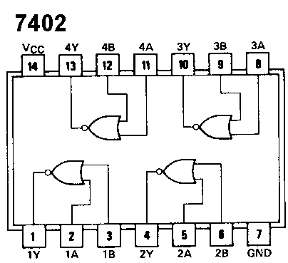
This has been quite a while since I did all this. I actually started learning a little about the logic probes and the Boolean Algebra and all that, but it is really foggy so I must start back and do it over again.

I guess my first question will be what can I put in place of the coils so I can test the IC's with a probe and all that without burning up another coil? Any type or size of a resistor I can slap in there while testing?

Thanks, Bill

#2 10 years ago

Also I converted a desk top power supply to a desk top power source. It was from a tutorial similiar to this one.
http://jumperone.com/2011/06/atx-power-supply-tutorial/

How can I get the cpu to boot from this?

#5 10 years ago

Thanks for the replies, could someone help me hook the power source up so I could test the IC's while the board is out of the machine? < ( I need a couple hip replacements so I'd rather sit and check this) < and try to learn what the hell I'm doing.

#7 10 years ago

OK, I will. I just glanced at that but are Sys 11 and 11a close enough for me to follow his tutorial? I would assume yes, but like I've said I'm just trying to learn

#9 10 years ago

Yeah I don't have a eprom programmer?

#11 10 years ago

Thanks, this is all over my head right now. I did buy all the components that are in the circuit with the diverters. I was just going to "Shotgun" it and replace them all, but it sure would be nice to know what's up and do it like I know what I'm doing.

#13 10 years ago

Thanks, I'll give that a read. I've watched most the videos from Randy Fromm, he makes it pretty simple to understand also. I need to refresh myself on all of them, to be honest I hand a time remembering what the components before some? transistors are called. I had to Google search it. "pre-drivers" is what I was looking for. Last time I replaced them I just called them "little guys". I guess I should make it a habit of calling them by name

#15 10 years ago
Quoted from barakandl:

Pre drivers are transistors too. Just those ones are in a different smaller package. In pinball they have to go from a low current 5v PIA signal to high voltage/current driven device. In solenoids you normally go PIA -> logic (either decoder or some kind of gate) -> pre driver -> TIP102 main driver.
With transistors typically there are many of the same kind on the circuit board. This is good because you can compare it to the other ones with you DMM on diode test mode.

Glad you brought that up, I just happened to be testing the Q79,77,75 transistors while on the board. They're TIP 102's.. I have my DMM set to diode and am getting weird readings on the board and even on the new ones I have never installed.
On the legs of the 102 transistors its Base Collector Emitter from left to right if I have the transistor laying with the metal tab flat on the table right?
Well on all my transistors even my new ones if I place my red lead on the Base and my black lead on either the Collector or the Emitter I get the .6v or so voltage drop. That reads good.
I switch my leads around Black is now on the Base. I get "open" to the Collector but I get a voltage drop of like 1.198v on the Emitter... I thought I was suppose to have "open" on both Collector and Emitter when my Black lead is on the Base.?
When on the board I basically get the same thing except the 1.198v described above is only .589v or so
Is my DMM messed up or what?

#16 10 years ago

I found part of the old PinRepair pages that tells me to test them this way.

"TIP102: Put the black lead of the DMM on the metal tab of the transistor. Put the red lead of the DMM on each of the two outside legs of the transistor. A reading of .4 to .6 volts should be seen. Put the red lead on the center transistor leg (collector), and a zero reading should be seen. Any other value, and the transistor is bad and will need to be replaced."

I take it as this test in this video below isn't for TIP102 transistors?

#17 10 years ago

If electronics weren't confusing enough for me I found this on the Pinball Rehab pages about Darlington transistors, aka the TIP102's I've been testing

"Remember that Darlington transistors can sometimes give odd readings, generally from the base to the emitter. The datasheet will show the internal circuitry and provide an indication that you should expect "abnormal" readings. On a TIP102, for example, when testing with the black lead on the left leg and the red lead on the right leg, you will get a reading of about 1.9 volts instead of open (this is because of the internal resistors)."

#19 10 years ago

Well I made it to the paragraph that starts with "There are 7 PIA'S ( U51, U10, U38, U54, U9, U41 and U42)" from the pinwiki link that barakandi posted and of course I got confused right there.

I do have my power supply hooked up to the cpu and have +5v r8unning, I have the diagnostics led flashing like mentioned in the pinwiki page

#20 10 years ago

Looking at this schematic I see that U50 (an 7402IC ) has pins 11 and 12 that are input pins for the output pin 13. This goes to pin 5 of U56 ( 7406IC ) right? I've marked the area I'm talking about with a red arrow
U50 is on a socket, if I pull it should I get any activity at U56 with my logic probe?

U50_F14_schematic.jpgU50_F14_schematic.jpg

#21 10 years ago

I also just looked up that the symbol on the schematic for U56 is an Inverter symbol? Not that I really know what that means I just notice it was different than the Gate which now I see is a Nor Gate symbol.. And deeper and deeper down the rabbit hole I go..Haha

#22 10 years ago

Anyways with U50 removed pin 5 of U56 is dead but pin 6 is Low

edit: If I put U50 back in I get a Low signal at pin 5 of U56

#24 10 years ago

Dang it, I thought I was onto something. Thanks for correcting me and thanks for kind of holding my hand I do appreciate it. I will get this stuff some day, kinda wish I did wait till I was almost 43 to do it but hey better late than never.

I'll look at the recommended pages.

#25 10 years ago

Also like I said and this is being said before I read what you just recommended, but I replaced those to trans. Q77 and Q79 already. I probably should put the new coils back in and see if theyu lock on again or not? I might have already fixed the problem and not even realize it. It's been a long time since I messed with this machine. I was afraid I would burn the new coils up if the 2 transistors weren't the issue, that is why I asked about putting a resistor or something in their place to test things.
I know I sound like an idiot but I figure I have to start some where?

#27 10 years ago

Ok, I scanned that Special Solenoid schematic. Of course I need to ask questions as to what I am looking at, so I marked this scan with some red numbers. I have to work backwards I guess? I'm just going to concentrate on one diverter coil even if it isn't locked on, just to see if I can figure out what I'm doing. I'll take Sol 22 from pg. 27 of my manual, the Lower Diverter-Launch Ramp coil. AKA Special Coil #6 which is controlled by transistor Q79

1. So, for the sake of me learning I'll call this Sol. 22. I see that it has +34 volts on it, I assume AC volts for a coil right?

2. This is the Output connector right? Should I have any DC voltages on these pins? Back to the Sol. 22 on the 1st schematic it says that IJ19-9, so that's CN IJ19 and Pin 9 right? What does IJ18- 9 do?

3. This is Q79, when I have 5 volts hooked up to the CPU how do I test this to make sure it is "Off" ? It should be "Off" right? If it was on that is what would give the 34 volts a path to ground and make it fire the coil right?

4.This is just the Pre driver Q78 from the schematic I guess I'd ask the same questions as above for this

5. This is IC U50 and looks like the output on pin 4 of it controls the pre driver then onto the transistor and so forth. What should pin 4 be with a logic probe with my cpu out of game with only 5 volts hooked up to it?

? ... I guess I should have made this 6. but I don't know where this PIA 7407 is on my schematic. spec_solinoid_schematic.jpgspec_solinoid_schematic.jpg

#28 10 years ago

I know I just proved it << I don't know what I'm doing

#30 10 years ago

Hey thanks at least I know what another symbol on the schematic is now. I never even really paid attention to those square waves. That makes a lot of difference when I'm poking around with my logic probe. I only knew what the reading was on the probe, say High or Low or Pulsing.. I hadn't a clue as to how to look at the schematic to see if that reading was correct or not.
Thanks for the patience

#31 10 years ago
Quoted from terryb:

5. U50 input low and output high when the solenoids are not energized.

This one got me, isn't that what the "on" schematic shows Low input to the 7402(U50) with an output of High to the predriver(2N4401).. which would energize the coil?

#33 10 years ago

With the board booted from a desktop power supply I have a Low signal on pin 4 of U50 So I should be OK right? I checked the the transistors and they seem ok. So what else should I test before I plug it back into the machine? Besides the other diverter coil.

#34 10 years ago

If I go through and check all the pins on U50 I get the following with my probe
1. Low
2. High
3. Low
4. Low
5. High
6. Low
7. Low
8. Low
9.Low
10..Dead
11. High
12. Low
13. Low
14. high
Why is Pin 10 Dead?
Edit: Looking back at the F14 schematic, I think that pin 8,9 and 10 have to do with the Blanking Signal.. Another mystery to me.

#36 10 years ago

I edited the post where I asked about Pin 10.. I believe it has to do with the Blanking Signal.. Where I put my 1st red arrow. I checked again and 10 is dead. Pin 1 is to the left of the notch on the package and is also marked by a dot on this Williams board right?

SN74F02-pinout.jpgSN74F02-pinout.jpg

#37 10 years ago

edited and reposted

#38 10 years ago

Just was reading, so the only way to get a High on a NOR gate is two Low's ?

edit: I guess I should have said a 2-input NOR gate

#39 10 years ago

Here is a little closer look at the schematic.

I see that U50 Pins 11High and 12Low have an output of 13Low that goes into the inverter U56 at pin 5Low .. Now if I check U56 pin 6 why is it still Low?

// Error: Image 117282 not found //

#41 10 years ago

I checked Q67 that is the transistor on the schematic that you described. It's a 2n4401, like the pre-driver trans that are before all the special coils. Using the center leg with first the Pos lead and then Neg. lead I have a voltage drop to both Base and Emitter from Collector both ways, about .601 volts.

I'll replace U56 later tonight after the garage cools down some. U50 is already on a socket and I checked continuity from from U56 Pin 6 to U50 Pin 8 & 9 and I get a buzz, so I guess it's alright

Thanks for the reading material. I'll try to read it a couple times and see if I can comprehend it.

#43 10 years ago
Quoted from terryb:

So you're also replacing U50?

Yes, I was just saying that the socket of U50 not the chip itself should be OK since I have continuity from U56 Pin6 to U50 Pin 8 & 9.

#44 10 years ago

I looked up the 2N4401 and see that it's leads or "pin outs" are not the same as a TIP102. The 2N4401 is E B C instead of B C E like the 102's..
Now I want to test the 4401 Collector to Emitter and then Collector to Base. Then reverse my leads right?
If that is the case, I only get a junction drop of .159 volts with my Pos on Collector and Neg on Emitter..
Also the 4401 Q67 doesn't read the same as the 4401's behind Q79 and Q77.. I get a drop close to .5 and above. So I take it as Q67 is shorted right?

#46 10 years ago

Hmm? I get voltage drops everywhere on all my 2N4401's.. I can test some I have that aren't in circuit and they show like you described

#48 10 years ago
Quoted from terryb:

Base is always the reference. On the 2N4401 check from base to collector and then base to emitter. Reverse leads and repeat. Last test is from collector to emitter, which should be open.

Where you say I should be Open here I have a voltage drop. No matter where I place my leads I get a VD

#50 10 years ago

Seems all test about the same so they must be fine.
I have to wait on a replacement chip for U56, the 7406 inverter. So, I'm kind of on hold till it arrives.

#52 10 years ago

Yep, mine does too. I don't think there is much that can be done with that besides just replacing with a new LED one. I'll probably never do it for my machine. I pretty much bought this machine just to learn with, it's not worth dumping money into. Everything about my F14 is rough.

#53 10 years ago
Quoted from BillinIndiana:

If I go through and check all the pins on U50 I get the following with my probe
1. Low
2. High
3. Low
4. Low
5. High
6. Low
7. Low
8. Low
9.Low
10..Dead
11. High
12. Low
13. Low
14. high
Why is Pin 10 Dead?

I replace the 7406 inverter U56 and also 7402 U50 NOR gate and I get the following readings with a Logic probe, Looks like it helped out.

Pin 1 low
pin 2 high
pin 3 high
pin 4 low
pin 5 high
pin 6 high
pin 7 low
pin 8 high
pin 9 high
pin 10 low
pin 11 high
pin 12 low
pin 13 low
pin 14 high

Still being a Rookie, I think these signals look better , it changed a few from low to high and also took care of the dead pin 10..
Anyways I only have the board hooked up to 5 volts on my desktop power supply, but a good thing... No Smoke

#54 10 years ago

Also U50 input Pins 11 High and 12 Low have output pin 13 Low. Pin 13 goes to the inverter Pin 5 of U56 as a Low and comes out pin 6 High like I believe it should.

U50_Pin_10_dead.jpgU50_Pin_10_dead.jpg

#56 10 years ago
Quoted from terryb:

Did you ever have any doubt?
You're definitely starting to pick this stuff up Bill.
One other thing, whenever you have solenoid problems it's a good idea to test the solenoid and the solenoid diode before installing the board. Both can be checked with a DMM.

Thanks for all the help Terry.. Sorry I'm a little slow at all this.
As far as the solenoids, they're new because the old ones burnt up, but I'll check them to make sure. It will be awhile before I get around to putting this one back together, but I'll get it and let you know how it all works out. Hopefully it will be all good news

Bill

#57 10 years ago

One more question, so does the single output of U56 pin 6 control the signals of U50 pins 3,6,8 and 9 ? See how they all seem connected on the schematic and all have changed from my earlier signals to the signals after I replaced the inverter.

u56_pin.jpgu56_pin.jpg

#58 10 years ago

I never checked any signals on U45, so I have no clue if those changed also

#59 10 years ago

I found this so I think all the input to outputs are correct.

""The truth table of each individual gate is:

input B input A output
0 0 1
0 1 0
1 0 0
1 1 0
NOR gate truth table
where '0' represents a LOW voltage, and '1' represents a HIGH voltage.""

Also in the "On" position of say the coil controlled by trans. Q79 the two inputs would be Low according to the Special Solenoid mini schematic.. So if I look at Q79 I see they would be pin 5 & 6 of U50. The mini says 5 should be low in the on position and 6 should too because the flippers are enabled. Since the game would be in attract mode they wouldn't be, so the signal to pin 6 is High.. I'm not sure what determines pin 5 to be High. I understand that it is High because the solenoid is off, but don't know what changes it to Low when the solenoid is energized? Unless it is switch IJ18-9 ?

Q79.jpgQ79.jpg spec_solinoid_schematic_no_nums.jpgspec_solinoid_schematic_no_nums.jpg

#61 10 years ago
Quoted from terryb:

I'm more familiar with WPC games than system 11, but normally the input would be controlled by a PIA (peripheral interface adaptor). The PIA takes commands from the CPU and then switches individual circuits on and off.

I guess I could have looked back to the special solenoid schematic, I see now that there is a 7407 PIA right there on it. I was looking more at the solenoids on the CPU schematic that actually show transistor #'s and all that when I ask this question

#62 10 years ago

Plugged the CPU back in tonight. I thought I had an issue with the Right Center Eject but the switch actuator was just stuck. When I powered on I got the single tone from the sound board being OK'd and the game went into attract-mode. Put a few credits on it and from what I can tell with a partially disassembled PF the issue is solved.. I can manually hit the rollover switch in the launch habit trail and the special solenoid engages just like it should. No smoke or anything..LOL

Thanks TerryB for all the help and patience. Now I guess I might as well tear the rest of the PF down and see if I can make a silk purse out of a sow's ear.. < I dislike that expression but don't know what else to say. This machine is a serious mess and like I said I only bought it to work on the boards and maybe learn a few things. Oh well, I might as well get it playable and have some more fun.. It's only money and time... Time I have plenty of..

Thanks! Bill

Promoted items from Pinside Marketplace and Pinside Shops!
$ 69.00
Gameroom - Decorations
Pinball Pimp
 
$ 65.00
Playfield - Toys/Add-ons
arcade-cabinets.com
 
$ 39.99
Eproms
Matt's Basement Arcade
 
$ 18.95
Eproms
Pinballrom
 
$ 1.00
Pinball Machine
Pinball Alley
 
$ 19.99
Eproms
Matt's Basement Arcade
 
$ 2.50
Lighting - Led
Pinballrom
 
$ 35.00
Cabinet - Other
Rocket City Pinball
 
5,000 (Firm)
Machine - For Sale
Vandalia, OH
From: $ 100.00
Cabinet - Shooter Rods
Super Skill Shot Shop
 
$ 5.00
Playfield - Decals
Metal-Mods
 
$ 95.00
Cabinet - Sound/Speakers
Pinball Mod Co.
 
$ 25.00
Playfield - Decals
Pinball Invasion
 
$ 54.99
Cabinet - Shooter Rods
Lighted Pinball Mods
 
Wanted
Machine - Wanted
Fort Lauderdale, FL
$ 170.00
Displays
Digipinball Shop
 
$ 18.00
Electronics
Yorktown Arcade Supply
 
$ 36.95
Eproms
Pinballrom
 
$ 10.00
Playfield - Protection
UpKick Pinball
 
Hey modders!
Your shop name here

You're currently viewing posts by Pinsider BillinIndiana.
Click here to go back to viewing the entire thread.

Reply

Wanna join the discussion? Please sign in to reply to this topic.

Hey there! Welcome to Pinside!

Donate to Pinside

Great to see you're enjoying Pinside! Did you know Pinside is able to run without any 3rd-party banners or ads, thanks to the support from our visitors? Please consider a donation to Pinside and get anext to your username to show for it! Or better yet, subscribe to Pinside+!


This page was printed from https://pinside.com/pinball/forum/topic/back-to-my-f14-tomcat-with-issues-long-maybe?tu=BillinIndiana and we tried optimising it for printing. Some page elements may have been deliberately hidden.

Scan the QR code on the left to jump to the URL this document was printed from.