The clear pop bumper is the one thats cut off to fit.
(Topic ID: 257696)
 Addams Family, The
Bally, 1992
Addams Family, The
Bally, 1992You're currently viewing posts by Pinsider pinballinreno.
Click here to go back to viewing the entire thread.
Quoted from Shredder565:If I where to buy a Rotisserie, how much are they and what is a good place to go too?
Just build one out of pipe.
Vid's quick and dirty guide thread.
Its easy and inexpensive.
I built 2 of them.
Quoted from Shredder565:I try not too listen to naysayers.
It's entirely possible this may not get completed. May I direct your attention to KITT. An almost completed dash (I have since added the two monitors and fixed the position of some of the lights. .)
I just can't justify the money to buy a car to put it in..considering allth e work a used car would probably need.
A Pinball, however, I would play every day.
[quoted image]
As for wire, we have a wire sales guy here at work, Next time he shows up... I will give him the list posted here a while back and see what he might be able to round up.
Im a big fan of silicone wire right now.
Way more flexible, heat resistant, shrugs off dirt etc., should out-perform the original wire.
Quoted from Shredder565:looking up TNut info. it appears I need 8-32 and 6-32 sizes..
amazon.com link »
is this right for 8-32? seems there are more of these than the 6-32
Oddly, not just any t-nut will do.
Some have fit into recesses.
There are 4 or 5 different flange sizes.
So, Marco or pinball life, they post the outer flange diameters.
Quoted from Shredder565:Just done. I copied and pasted the list, and I sent over a photo of the wire harness..saying it was a few joined together to make one. I wanted him to forward the list and photo over to the company to see how gung ho they'd be about the project. hopefully it won't take too long to get a response back.
The wiring harness is the least of your concerns.
Its the hard assemblies and metal formed parts that have to be fabricated.
Quoted from metahugh:They are definitely out there. Here was mine pre-rebuild
[quoted image]
Good candidate for novus2 and some wax.
Quoted from Shredder565:nothing is secured yet. I will replace them with the proper screws tomorrow.
But, it's all in it's proper place. And I will probably place the chair scoop on too.
It's starting to look like something![quoted image]
Use better clamps on your rotisserie.
As the playfield gets heavier you want either c-clamps or high end ratchet clamps.
C-clamps offer the best security, just use a small piece of paint stirring stick to protect the surface.
I try to put a single bolt and nut thru the playfiled on each side with a washer if I can find a hole, to add security.
I have had playfields slip when turning before, they get heavy.
Quoted from Shredder565:I'm still waiting on my wire guys.
One of them wants me to use just one color wire, and label it. yes, it'd be cheaper that way...but I'd think it'd be ten times harder to trouble shoot without the correct color coding.
Also, is the wire in the wire harness stranded or solid? my guess was solid.
Stranded.
put a couple small c-clamps on that rotisserie for security.
the playfield gets really heavy as you add to it.
Quoted from Shredder565:I posted a lowes link earlier wondering what would be the best kind of c clamp to get...
Get a couple 3" regular c clamps
And maybe a set if the irwin hand/quick release ratchett clamps. The set comes with 6 assorted sizes. The tiny ones are not usable.
I have 2 of the 3" clamps as security.
I have had the quick clamps slip off a couple times.
Get a few of the samples for maple hardwood floors.
They are very handy to use under the c clamps. And they are free.
I use those hardwood squares for tons of things
you should get the reese rails now.
it will stabilise the playfield to keep it from warping from the weight.
or at least some kind of rails while waiting for them
Quoted from Shredder565:would these work? sometimes having a warehouse at work helps [quoted image]
Dont use drywall screws.
They are too brittle and the heads break off.
A #6 × 1-1/4" oval head or bugle head sheet metal screw is what you want.
Or
#6 ×1-1/4" flathead crosshead wood screw.
The V Head (similar to drywall screws) will keep the wood from slipping sideways.
Quoted from Ricochet:taylorva pre drills his rails for the correct screws
Yep, predrilled for tne #6
Fortunately cracks in oak are very easily fixed eith a little titbond and a clamp
Quoted from Shredder565:With thing Parts ordered so far, total spent on project?
Around $5,000
once the cabinet arrives, it'll at least start to LOOK like a pinball machine that is mostly complete ;o).
Now I have to go through my complete parts list item, and check off the part numbers I do have to see what's left of the 3,000 or so parts needed.
but at least I can take a break from part ordering for a few weeks again. next time we pick up, i'll get a plastics set, a dmd, and maybe the flippers set.
$8500 is right about what a new game would cost.
So, youre not too bad at all.
Quoted from Shredder565:I can't remember if the manual showed the star posts....I will have to look at it again.
but the ones I can't seem to locate are these two darker colored ones.
maybe under some plastics?
https://www.marcospecialties.com/pinball-parts/03-8319-10
PM the other restorers for pics.
Quoted from russdx:Pcbs are so cheap these days far easier to just send designs off, you get couple hundred made they are under a dollar each easy, plus you get a quality product with proper vias and solder mask etc... far better then anything home made which will be no where near the quality and takes ages to produce.
Plus you can actually just send in the boards and have them copied.
4 day turn around in a lot of cases.
Quoted from Shredder565:So, the bookcase build.
I think this sh aft has to go through to the other side but for the life of me I can't get it in..
is there something else to it?[quoted image]
One side of the shaft should be countersunk slightly to guide the pin in.
If not, countersink it.
Use your bench vise to press it in.
If the pin collapses, it wasn't straight into the hole. Use another one, Ace sells them.
An arbor press will also work but you will get more use out of a bench vice.
It'll go. You just have to have the right tools.
Harbor frieght has a good 4" one with anvil. that should be sufficient. Put a 14" piece of pipe over the handle to add torque.
You have to bolt it down to a firm surface or work table.
Roll pins are supposed to be very tight.
Quoted from Shredder565:tried a hammer, a wrench, the butt of a screw driver..... even with slight force didn't seem to work.. but it also wasn't secured to anything so I had to hold the pin mount while banging...
Line up the pin from the opposite side with a brad or small nail.
It has the be perfectly straight and aligned.
I have had to sharpen the end of some pins a bit to get them to start.
Stubborn pins are usually just not aligned properly.
One they start they go in pretty easy.
Get a vise.
You will need it.
Quoted from Shredder565:most of thing and the book case taken care of. hopefully that looks right.[quoted image]
Like I said, get a vice and a press brake attachment for it.
A 4" is probably all you need.
You will need it, as well as a drill press.
The Ryobi one is pretty good, there is very little slop in the arbor, and its inexpensive.
These tools are not expensive but for what you are doing, almost mandatory.
Quoted from Shredder565:before I place the order, which one of these is the right flipper rebuild kit?
https://www.pinballlife.com/search.html?Search=flipper%20build%20kit
I need 4...
You need complete assemblies.
And a short "thing" flipper bat
Quoted from Shredder565:so if I went with this one, what eos switch and coil do I use? and would I still need 4 or 2?
I obviously need bottom left right, thing flips and train kick.
Also, Irony....
and metal, glorious metal. how do these look?[quoted image][quoted image]
Dig up the coil stops and coils from the manual.
EOS switches are normally open on WPC games, also in the manual.
Look up the part number for the small flipper bat in yellow.
coil stops are important as they can restrict flipper travel if not the right ones.
Buy a vice and a press brake attachment.
Quoted from Shredder565:OK, does this look right? want to make sure I have the right things...
Also, for a press brake how is this?
https://www.eastwood.com/eastwood-4-inch-vise-press-brake.html?utm_source=youtube&utm_medium=annotation&utm_campaign=2018-09-11&utm_content=4%22%20Press%20Brake
we already have the vice.
Full Flipper Assembly For Williams/Bally Machines From 02/1992 To 10/1998
SKU: a-15205-r-2_a-15205-l-2
Location: L1
Choose A Base Plate: Right
Choose A Coil: FL-15411
Choose A Coil Stop: A-12111
$0.80
Choose An EOS Switch: SW-1A-194 Normally Open EOS
⋮ SAVE TO WISH LIST
Full Flipper Assembly For Williams/Bally Machines From 02/1992 To 10/1998 Quantity
Quantity
1
$39.95
$40.75
Full Flipper Assembly For Williams/Bally Machines From 02/1992 To 10/1998
Full Flipper Assembly For Williams/Bally Machines From 02/1992 To 10/1998
SKU: a-15205-r-2_a-15205-l-2
Location: L1
Choose A Base Plate: Left
Choose A Coil: FL-11753
Choose A Coil Stop: A-12111
$0.80
Choose An EOS Switch: SW-1A-194 Normally Open EOS
⋮ SAVE TO WISH LIST
Full Flipper Assembly For Williams/Bally Machines From 02/1992 To 10/1998 Quantity
Quantity
1
$39.95
$40.75
Full Flipper Assembly For Williams/Bally Machines From 02/1992 To 10/1998
Full Flipper Assembly For Williams/Bally Machines From 02/1992 To 10/1998
SKU: a-15205-r-2_a-15205-l-2
Location: L1
Choose A Base Plate: Left
Choose A Coil: FL-11630
Choose A Coil Stop: A-12111
$0.80
Choose An EOS Switch: SW-1A-194 Normally Open EOS
looks good to me, just verify your lefts and rights and it should be ok.
The eastwood press brake is a pretty good one and a fair price.
Get some cheap strapping metal from home depot to learn how it bends before tackling your printed pieces.
Quoted from Shredder565:i found the one wally has. it ships a little sooner than the other one by two weeks.
maybe i'll get this one.
amazon.com link »
That looks very good.
Quoted from bssbllr:Don’t mean to point this out but is this normal, also thanks for posting your work good job.[quoted image]
Good catch!
Quoted from Shredder565:nope! it went in crooked and i'm almost afraid to remove it as it's stable.
It may look stable right now but the constant banging and vibration of general use will quickly fail that area.
Its way easier to fix this now than later.
Bondo or epoxy wood filler to fill the area. Pre-drill a new hole the width of the inner shank of the screw, use a drill stop on the drill so you dont drill thru the surface, glue the screw in when you tighten it with titebond III.
It will hold.
Quoted from Shredder565:So, now that the ball trough is on..
what am i missing to attach the electric chair and the main ramp?
The ramps go on last after the bottom is complete and all posts, lights and flatrails installed.
Quoted from Shredder565:i know they've gotta be removed anyway, but what the heck...
[quoted image][quoted image]
On installing flat rails and flat guides:
As a matter of habit, a lot if us put #6 or #8 flat washers under the atrachment posts and bent feet to keep the flatrail from cutting a notch into the artwork over time.
Its not mandatory or factory, but its something restorers do.
I dont think the ball trough needs it though.
Quoted from Shredder565:I'm rather proud of getting that on the first try.
how does that look? deep enough?[quoted image]
The center line of a ball should be even with the center line of the ball guide
Quoted from Shredder565:I was going to celebrate the last part being bought as the three balls needed .
Read vids guide on re-populating playfield.
Just make the wire ball guides.
Cheap and easy.
Marco sells the perfect bender for $7
Quoted from slicknick13:last time I tried that trick, i blew out the bottom of a playfield by going too deep.
The holes are supposed to be drilled all the way through the playfield.
Top quarter of the hole slightly larger than the wire, the bottom half of the hole slightly smaller than the wire.
Use the drill box holes/guides to size the bits. Or lay the bits down next to the wire and check with a straight edge.
Hammer in using 1/2" MDF as a spacer. This gives you close to the exact height of 17/32" to the center
Glued in with titebond III.
Removal is easy with a small drift from the bottom.
Quoted from Shredder565:when I was looking at images, it seems they are also flipped the other way and metal against even wood obviously not good.
any ideas on where to get the spacers?
Do you have the twist on sockets for the boards?
Any 1/2" #6 spacer will work.
Ace hardware usually has a good selection of black nylon spacers.
Marco has the clip on ones specific for this.
Someone here can measure the exact length or check the BOM list.
Quoted from Shredder565:one more order from marco.
Diode - 400 volts 1 amp XO-254 15 $0.16 $2.40
ADDAMS FAMILY (Bally) Bookcase opto board set 1 $37.95 $37.95
Machine Screw 8-32 x 5/8 inch p-ph 4 $0.15 $0.60
Rubber ring - White 27/64 inch or 7/16 inch OD 4 $0.25 $1.00
Cable clamp holder 1/4" diameter 2 $0.29 $0.58
Sheet Metal Screw #6 x 5/8 inch p-ph t-25 2 $0.31 $0.62
ADDAMS FAMILY (Bally) Bookcase lens 4 $4.95 $19.80
Machine Screw 8-32 x 1/2" p-ph-sems 1 $0.15 $0.15
Machine Screw 8-32 x 1/2" p-ph-s 1 $0.20 $0.20
Mini post - wood screw thread 1 $2.89 $2.89
Lamp #44 miniature - 10-pack 20 $1.95 $39.00
Flipper & shaft - Williams logo yellow 3 $5.25 $15.75
.156 inch 24 position male header 5 $2.50 $12.50
Dont put #44 lamps in the game or on the light boards.
They melt inserts and warp plastics.
Get 2smd frosted sunlight LEDS in #555 wedge base and #44 bayonet base from cometpinball.com
When installed look exactly like #44 bulbs.
Use them for everything.
Get 100-150 of each to start and get the 25 pak 5smd towers for the #906 bulbs. A few 8smd towers for the #89 bulbs.
You also will need the coin door/cabinet interconnect board for the cabinet.
This is often overlooked when shopping for PC boards.
You will also need the LEDOCD board for the LEDS, its important, you can install it at the end.
Quoted from Shredder565:hmm, that's what was listed in the manual....good to know.
I'll look up the info. thanks to ye old government stimulus check finally arriving, I have a tad more leeway.
Yes, #44 bulbs were the standard 30 years ago. We always traded them out for #47 bulbs to not kill all the plastic in the game and blow off the pins on the pc boards with high current.
People have never really seen a game with #44 bulbs (nearly all were traded out immediately), they are super bright! #47 bulbs are very dim in comparison but, run at half the power and brightness and dont get as hot.
2smd frosted bulbs are the perfect solution as they look like the original #44 bulbs without the heat and power draw.
Quoted from Shredder565:OK, I found the first two bulbs.. for the above..which one of these?
https://www.cometpinball.com/search?q=5smd+
https://www.cometpinball.com/products/2smd-bulbs-100-packs?variant=12093843341356
Choose the base type, color and lens type
wedge or bayonet, sunlight, frosted
https://www.cometpinball.com/products/5smd-flashers?_pos=9&_sid=4402beb8a&_ss=r
get the 5smd flasher/towers not the 9smd ones
everything else looks ok.
You might also get one of these if you dont have something similar already:
https://www.amazon.com/YIHUA-Soldering-Station-Charging-Voltage/dp/B07S4GPM66/ref=sr_1_3
Very handy for shrink tube and has a power supply to test lamp boards, connectors, pc boards and motors before installing
In a pinch test the lamp boards with a 6v battery made out of 3 AA batteries. Or just dial it in on your workstation (its what I do...)
Quoted from Shredder565:so, something like these guys?
https://www.cometpinball.com/products/5smd-bulbs-25-packs?variant=29411775184998
just making sure i have the right ones
no.
get the 5smd towers, they match the #906 bulbs. they have to shoot sideways. cool white.
https://www.cometpinball.com/products/5smd-flashers?_pos=9&_sid=4402beb8a&_ss=r
Quoted from A_Bord:I would argue for warm white LEDs since they better mimic the color of incandescent but to each his own...
Yep.
Warm white for a #47 dim look that people are used to, or super old silvered-out #44 bulbs that glow yellow on older games. You put in new #44 bulbs and they arent that yellow any more
Sunlight for a brighter #44 look as was initially on the game when new.
Its a matter of what you are used to. But after doing a few games, the sunlight looks like a fresh new #44 bulb and doesnt alter the colors around it with too much yellow like the warm bulbs do.
Still its a matter of preference!
I now use exclusively sunlight bulbs unless there is maybe one or 2 inserts that I want to alter.
Quoted from Shredder565:unless this is the 5 version.
https://www.cometpinball.com/products/5smd-flashers?_pos=1&_sid=12f355875&_ss=r
yes 5smd flashers (used to be called towers back in the day lol)
#906 bulbs are used for flashers, so...flashers.
Quoted from Shredder565:ordered
I think that'll be it until June when I get some other parts from one poster and some CPU boards from a poster here.
Now you can insert wedge sockets and test the boards after they are assembled.
Once you get the leds.
Quoted from Shredder565:it would be nice to power up the light boards at least, to make it seem a little closer to completion ;o).
I was thinking of upgrading to LEDs, but I wanted the cathode look of original. We'll see how it all turns out .
On the leds, when you get them,
Fan out the loose wire ends on both sides before installing them.
This insures permanent contact and eliminates vibration flicker.
Before
20200516_102459 (resized).jpg
After
20200516_102604 (resized).jpg
This is true for all wedge base leds.
Bayonet base LEDs dont have loose wire ends.
Quoted from Shredder565:it would be nice to power up the light boards at least, to make it seem a little closer to completion ;o).
I was thinking of upgrading to LEDs, but I wanted the cathode look of original. We'll see how it all turns out .
Populating the lamp boards and testing them before installation is a good idea.
In fact the lamp boards and pc boards are the first things to install on the playfield when rebuilding.
So, you could install them now.
If your workstation doesnt have a variable DC out for testing, you can just use a 4 AA 6v battery for tesing lamps:
https://www.amazon.com/AA-6V-Cell-Battery-Holder/dp/B003J8MV8E
The batteries are simply wired in series.
The #906 and #89 bulbs are 12v, so a 12v drill motor battery works in a pinch, or just make up a battery.
Quoted from Shredder565:Yep I have a 12V Battery and the smaller one handy.
as for soldering stations, I just have a basic soldering iron. nothing fancy.
The one i posted earlier from amazon sure looks purdy!
Quoted from Shredder565:I hope ramp placement one looks good cause it's in. the rest coming shortly.[quoted image]
Looks great!
Quoted from Shredder565:So, I am pretty s ure these two posts go here.
but how do they attach to the siderail there?
[quoted image][quoted image]
Some posts have a little bracket on the bottom to screw into the side rail, its painted black
8-32
https://www.marcospecialties.com/pinball-parts/A-12258-3
6-32
https://www.pinballlife.com/metal-hex-spacer-mounting-bracket.html
Then they are attached with #6 or #8 black truss head screws.
Someone should have a picture.
Quoted from Shredder565:hmm, looks easy enough.
I'll order a few. Thanks .
Once the 8-32s come back in stock.
Found those two posts and the 02-4436-15 locations. that just leaves 02-4435 and 02-4434 to figure out.
Also got a few CPU boards ordered this week. an original working Driver board, audio board and CPU board.
Nice.
The audio boards can be hard to get.
But theres always pinsound in a pinch.
Quoted from Shredder565:Todays job. some shipments came in. Flippers. Thing Magnet Coil, Diodes (Somehow mis counted short by me).....
No lights to populate yet though. But I do have the old ones socket free
How do the flippers stay attached to the rod?
I also have to figure out where those rails go.
[quoted image][quoted image][quoted image]
The mechs hold the flippers in
The flipper pawls clamp onto the flipper shafts.
The return spring at the end of the pawl hooks into the small hole above the EOS switch mount
Quoted from Shredder565:Also, which pins are the Ground/Power for when I get my lights
Your soldering is ok.
Are you using 63/37 solder?
Its better and slightly lower temp than 60/40.
Its also flows easier and sets faster.
Maybe a dab of flux and reheat a couple weak and cold joints.
The components are on the correct side, the lamp side.
The triangle is for the missing pin.
When you make the connector you will put a little blocking piece in that hole to keep from installing the connector backwards.
Familiarize yourself with the schematcs.
The power and ground are listed there.
You will need this skill/knowledge coming up when you make the harnesses.
Quoted from Shredder565:It was hard to tell from the angle, but it looked like the longer prongs of the header where facing the same direction I had them? maybe I guessed wrong.
Good catch.
The cable clips should be visable on the outside if this header has them...
Long pins up, short pins down...
Quoted from Shredder565:I am not the best solderer so how does that look?
I used up the last of my diodes so will have to order more. I guess they where out of stock and only had 15 to send.
[quoted image]
Much better, now you can plug on a connector or remove a bulb from it if necessary, while its mounted.
Looking at the traces probably pins 1 and 5 are power and ground.
Cut off the pin #4 (marked by the triangle) that has no trace to it.
Your soldering is good enough and will improve.
Quoted from Shredder565:Solder added to the cart. it says 300W Max on the side. not sure if that is what it is or not . again, not an solder expert
I've only done it once before with R2 and that was for his lights and sound.
Im using this solder and its very good, I stopped using 60/40 years ago and will never go back:
https://www.amazon.com/MAIYUM-63-37-Solder-Electrical-Soldering/dp/B075WB98FJ/ref=sr_1_1_sspa
I have that weller 40w station you listed its very good and will last years, its in my tool box.
But I encourage you to get the little air/power/solder station I listed above for the workbench.
I use one like it all the time.
Quoted from Shredder565:Nope, it was definitely the one in the link I provided above .
https://www.mcmaster.com/rosin-flux-core-solder
any of these solders do?
I need to order more screws from them anyway and it can get here tomorrow . might as well order from the same place.
any of the 63-37 solders.
.031 diameter is thin and controllable, easy to melt, low heat. Most people use it.
Lower heat saves your boards and it nice if you have to desolder and resolder.
.050 diameter gives you a little more solder but also holds more heat.
I use the .031 and just shove more on when I need to.
Ive been using silicone finger tips for awhile now and find them particularly useful when doing close work.
Wires get too hot to hold and you end up doing a poor job.
something like these:
https://www.amazon.com/Silicone-Protectors-HotGlue-Adhesives-Scrapbooking/dp/B07QQMJVWF/ref=sr_1_7
Quoted from Walamab:I ordered them from PSPA.
https://www.pinballspareparts.com.au/a-17838-1.html
It took a while for them to get here .
6 ro 8 weeks shipping from Wayne right now.
Quoted from Shredder565:when your comet LED order gets diverted to Puerto Rico for some reason.... :/.
ahh, modern virus shipping...sigh.
Your cabinet was shipped?
When did you order it?
I have one in the que, waiting to be built from 7 weeks ago.
Im hoping mine gets built in the next couple weeks.
Quoted from Shredder565:Nope, I wish It was, and if it where not for this virus, it probably would have been by now.
The cabinet maker had to send all his workers home. it's still being worked on, but understandably slow.
oh well. I am willing to wait for quality. I just hope it's not delivered a year from now .
It's my LED lights that shipped and should be here by tuesday. they are out for delivery now.
I was just curious though. my lights will have sockets with them, yes? I will not have to order those separately from comet?
Twist in wedge sockets are not provided/included automatically by comet, just the bulbs.
Marco or pinball life has the twist in sockets.
Quoted from Shredder565:Any links t othe correct ones? would be nice to get something around at the same time.
#555 /(1/2" hole in pc board):
https://www.marcospecialties.com/pinball-parts/24-8767
Large for #906 bulbs (5/8" hole in pc boards):
Quoted from Shredder565:Nope, I wish It was, and if it where not for this virus, it probably would have been by now.
The cabinet maker had to send all his workers home. it's still being worked on, but understandably slow.
oh well. I am willing to wait for quality. I just hope it's not delivered a year from now .
It's my LED lights that shipped and should be here by tuesday. they are out for delivery now.
I was just curious though. my lights will have sockets with them, yes? I will not have to order those separately from comet?
Michigan is opening up in a few days.
Hopefully Paul can get some help at his shop.
He has done his best all by himself. Im sure he will pull thru.
Quoted from Shredder565:No doubt . I don't doubt it'll get done. just a matter of when thanks to unforeseen circumstances on anyones part .
I'll order a few of each.
Has anyone done the return process through marco? thinking of returning the 44's and saving $40's.
They can give you a credit, im sure you will use it.
Quoted from Shredder565:Now that June is soon apon us... mid june, I will focus on getting the last two cpu boards needed for the back box and the color dmd. I'm hoping by then my cabinet will be getting closer to shipping :0).
I have located a awesome wireform ramp that is purchased. another order in reserve until it arrives. don't want to announce that one till I have it in hand .
After that, not sure where I should focus my parts search on. The Guide Rails will be mostly done. the light pcbs will have been properly soldered. the targets are in, the pop bumpers are in, the flippers are in. most of the posts are in. THING hand is complete. Bookcase is nearing completion. Lower Ball Guide and trough are in. it feels like 50% of the big stuff, or at least the most expensive stuff, is out of the way.
Your half way there!
Quoted from Shredder565:[quoted image]
so, which one of these sockets will go with which light?
https://www.marcospecialties.com/pinball-parts/24-8767
https://www.marcospecialties.com/pinball-parts/24-8803
The small are #555, all of the lamp boards, some backbox.
The large are 12v #906, mostly flashers For the 5led flashers.
Check the BOM there arent too many 906 twist.
Mostly in the domed flashers
Quoted from Shredder565:I thought thing flips was the normal sized flipper and the train was the smaller one. always get things reversed....will flip over.
Thing is a mini flipper.
Quoted from Shredder565:the other two recomendations where these suckers.
https://www.marcospecialties.com/pinball-parts/077-5002-00
https://www.marcospecialties.com/control/keywordsearch?SEARCH_STRING=+077-5006-00
In other news... oh man oh man oh man..
https://www.facebook.com/teenagemutantninjaturtles/videos/733850714019930/?v=733850714019930
For the #44 bulbs you will have to make a map of the socket lengths for the GI bulbs.
Generally you will use 3 different lengths of sockets depending on their use and location.
Its very helpful to access a completed game and map out the bulbs.
The BOM will list the sockets you need.
Pictures of other restorations might help with the locations if no game is available.
Some #44 bulbs are also used in the controlled lighting of inserts.
Socket lengths vary depending on location.
Some will have to have diodes installed.
Use gold 3/8" or 7/16" playfield screws for lamp sockets.
Always check the screws against the playfield thickness. Especially with repro playfields.
Quoted from Shredder565:I was oddly looking at that myself the other day and I hope it's just an illusion. I'll check again when I flip it back around. as for now...
let there be light![quoted image]
Nice!
Quoted from Shredder565:unfortunately, it does look like it's a little off center of the hole. not much, but enough.
Side drill the hole (put a collet on the drill bit: https://www.dubro.com/collections/collars/products/nickel-plated-dura-collars) enough to center the mech.
Put a 3/8" piece of bamboo skewer in the hole with a little titebond 3.
5 min fix that will last years.
All holes will be fixed this way permanently.
You will strip out several during construction and there will be mistakes.
I have filled 1/4" holes this way with several pieces of skewer and dry time in between. Holds rock solid.
Quoted from Shredder565:they looked like two different connections. I didn't think they'd fit.
Put a wedge socket there.
Quoted from Shredder565:I just pulled a 44 bulb out of it's metal socket and tried to fit it in the black one. and no go. either I'm twisting it in wrong, or it just won't fit. the socket itself fits into the board just fine. it's the light that has trouble fitting.
all boards now secure. just trying to find the placement of the other 44s next.
Use a 555 bulb in its twist socket in the hole.
It wont fit? Or the twist socket wont fit in the pcb hole?
Im confused.
The pcbs only have twist sockets in them.
Quoted from Shredder565:I just pulled a 44 bulb out of it's metal socket and tried to fit it in the black one. and no go. either I'm twisting it in wrong, or it just won't fit. the socket itself fits into the board just fine. it's the light that has trouble fitting.
all boards now secure. just trying to find the placement of the other 44s next.
It should be the same as all the other lamps in twist sockets that you mounted.
Quoted from Shredder565:The 555 bulb in it's twist socket will not fit. correct.
The 44 bulb in the socket for the smaller black connector will not go in that black socket. it only fits in the metal one. The black socket itself fits just fine. only the larger black socket for the 555 will not fit. and the manual states a 44 bulb should go in those two spots.
The larger twist socket is for a 12v #906 bulb or 5led flasher.
#44 insert bulbs in their sockets generally fit to the side of a pcb and are bent at an angle or nearly flattened and peek underneath.
Since you have aftermarket boards im not clear on the differences.
But post 1102 doesnt show a 44 socket there.
Put in a small twist socket snd 555 bulb.
Manuals are often slightly wrong.
Either way, what you have shown looks incorrect.
Quoted from Ricochet:Those two spots are not for a 44 bulb... they are for a 555 bulb. Is the PCB mis-aligned so the bulb is actually hitting wood?
Yep, is the bulb hitting wood?
Pcb might be misaligned.
Quoted from Shredder565:I took out the 44 and put in two 555's that went in ok.
it was the larger of the two sockets, that didn't fit.
That would be correct.
The larger sockets are for #906 or 5 led flashers. You will find them sometimes under domed flashers or on ramps.
There are only ever a couple of them in the game.
The 5 led flashers are polarized.
If they dont light when tested, turn them around.
$906 and #555 bulbs have the exact same wedge base but they are not interchangable in the game.
#555 is 6.3v
#906 is 12v
Quoted from Shredder565:thank you kind sir.
I know things got a b it confusing with the light info. what brackets do I need to attach the 555's to the board (the ones that don't have a PCB to attach too?)
these:
Quoted from Shredder565:one more guard rail in. now to figure out where the rest go.
I still have yet to bend that other end piece into more of a circle.
I just realized these are extra pieces with the order. maybe I got some of another persons by mistake?
[quoted image][quoted image]
Look like funhouse side art.
Quoted from Shredder565:Looks more like pieces to a bridge to me.
This:
https://www.pingraffix.com/product-page/funhouse-pinball-mirror-bladez-bally-williams
Or a bridge lol
Quoted from hoby1:For just the PF..... holy christ
He bought a cab from paul, with decals and paint.
Quoted from Shredder565:all but $2,000 almost right there.
Any word from Paul on your cabinet?
I ask because i think im right behind you as far as production.
I get more out of this riveter than any other:
https://www.erivet.com/product_detail.cfm?itemNbr=HT-174
I use this one a lot too, it uses the Hanson dies just like the pinrestore one (which i also have):
http://www.arbortime.mountainminded.net/html/the_better_tonka_rivet_tool_-_.html
Quoted from hoby1:I also have the first one... I put in my drill press and press the rivets rather than hammer them
I do this too.
But i find more and more uses for the pintonka one, its pretty slick.
Quoted from Shredder565:if memory serves, we already used something like this on the proton pack and have a drill press in the back.
https://www.mcmaster.com/rivets/rivets/aluminum-domed-head-blind-rivets/
But, if I rivet them out of the hole, I'd have to drill the hole a little bigger so they fit in and then put a nut on the end of the spade bolt.. ( I didn't check to see if they went all the way through the board to fit a nut)
Pinball machines use tubular rivets.
Head goes on the sheet metal side.
The spade lug should penetrate the playfield so you can put a nylock nut on it with a washer.
Pro tip:
Put a washer on top of the spade lug too, on rhe topside of the playfield under the flatrail.
This will keep the flat rail from cutting the artwork over time.
Quoted from Shredder565:which size rivets do I want?
I can afford these now at least ;o).
https://www.hansonrivet.com/rivets/tubular-rivets/
Get the assortment at pinrestore.com
Quoted from Shredder565:this?
>>>Master Rivet Kit
This is a neat little kit with 240 rivets and 120 backing washers. Each kit contains the following lengths and quantities of 1/8" diameter nickel-plated brass rivets: 5/32"x40, 3/16"x40, 7/32"x40, 1/4"x40, 9/32"x40, 5/16"x40. Each kit comes in a plastic divided box.>>>
Yep
Quoted from loneacer:I bought the rivet die set from pinrestore and attached them to a metal c clamp that I could twist by hand to install rivets into plastic assemblies.
This clamp to be precise, but it was silver when I bought it. I got rid of the middle clamp, cut the ends off the other two, and attached the rivet dies to those.
amazon.com link »
Yes, poor mans tonka clincher!
tonka wants $90 for an $8 clamp.
great solution.
Quoted from Shredder565:I'd be worried about something slipping and causing a malfunction in the process heh.
but it's definetly an option.
If I'm going to use it more than a few times on this, I don't mind getting the slightly more expensive item.
My Cabinet ships in 48 hours . Thank you Paul for getting it together under difficult circumstances . can't wait to see this sucker next week .
I want to see that Cabinet!
Tell Paul to get my Funhouse cabinet built PLEASE! Lol.
Quoted from NoahFentz:I had three other cabs to screen, so I screened yours, too. It'll be going out tomorrow, so the screens can cure.
[quoted image][quoted image][quoted image]
Gorgeous work Paul!
Now, about my funhouse cab.... ![]()
Quoted from NoahFentz:You're definitely in the next batch. This whole COVID thing has made life challenging, to say the least. No lumber, missing shipments of parts and supplies, and, of course, MANDATING we just completely shutdown here in Michigan for THREE months! Ugh.
I'm working 6-1/2 days a week to get it done!
Thanks Paul!
You and your staff are Rock Stars!
Thank you for everything you do.
Quoted from JIMAKOST:And since I still have it in hand the mystery Purchase and will be shipped tomorrow let’s reveal it.
Addams family playfield wiring for you !!
Now you can say that your game is 1000% legit and with an awesome cabinet!
You are lucky that I was able to remake it for my tafg otherwise I would keep for my self ,well it’s yours to enjoy here are some photos.[quoted image]
Nice work, now make 20 more. The community needs a few!
Getting the playfield to fit properly in the cabinet is next.
You might have to remove stuf to make it easier to handle.
Fitting the playfield can be a bit finicky.
I do it before its populated.
Quoted from Shredder565:what do I need to make sure it's stable in there? I was toying around with doing this next, just to make it look a little more complete, but figured it was too soon.
The only way is to attach the rear mounts and front hangers and see how it sets.
Make adjustments to the hangers as needed.
I also add black plastic washers to the pivots for both the head and the playfield to keep them centered so they dont scrape.
Getting these is mandatory so you font scrape up the cabinet during installation:
https://www.pinballlife.com/interior-cabinet-protector-blade-set.html
Quoted from Bryan_Kelly:I think what he's going to need are measurements for the pivot bolts and nuts. Paul doesn't drill those holes. I have an empty TAF cabinet I take take those off of, if need be. Not sure how you'd determine where those go otherwise.
I completely forgot that he would have to drill a couple holes.
Thanks!
An original cabinet measurement for the playfield pivots would definitely work.
The backbox hinge holes can easily be traced from an installed hinge.
Maybe set the hinges 1/8" out towards the edge from the factory location.
Quoted from Shredder565:Honestly, I would have thought that getting the playfield to fit on the swinging hinge would be the last thing to do. after all, you've got to take it back out to finish working on it.
Theres a little bit to it.
You want it to sit flat on the lockdown receiver and not scrape the sides when lifted for maintenance.
You also want it to lift "square" with the cabinet.
Otherwise the rear will scrape when it goes down inside.
Its way easier to check the fit with a blank playfield.
You might want to remove a bunch of stuff off your playfield to make it easier to work on the cabinet.
You will know a lot more when you get into it.
I spent a week getting a beat up Doctor Who playfield and cabinet to behave lol.
Its one of those things that seems simple on paper, but really annoying when it goes wrong.
Quoted from Shredder565:in this case, I had it on the wood bench.
So, whenever I get around to ordering a new one in late august....what edges do I need that will fit?
For printed backglass you only need the lift trim at the bottom.
If its CPR glass, get rhe 1/8" black plastic lift trim.
Measure the glass for lengrh. Like 27 or 27.5"
Glass trim cones in I/8" or 3/16" size depending on the glass thickness.
If loose use friction tape to hold it.
A 2" long piece in the center and at each end of the lift trim.
The sides and top plastics were to hold the translite on. You don't need them, unless you go back to a translite and clear glass.
Don't use metal tools on the glass it will explode.
I use wood blocks and a plastic hammer.
Quoted from Shredder565:you know, I was wondering about that...and figured I could try to fit it in without them. but I didn't want it to fall and break. irony
Cosmetically the plastic adds a "framed" look, but i honestly think that it subtracts from the art.
Earlier games with inked glass only use a metal lift channel.
That said, TAF came with a translite and black trim all around.
So for a "pure" look, i guess people put trim on printed glass though its not needed.
My personal preference is to only use the bottom lift channel. I think it looks better, but maybe thats just me.
On my funhouse CPR glass, the cabinet is blue. I thought the black frame looked out of place.
On my Diner CPR glass, the trim looked ok but removing the trim made tbe glass look bigger and more impressive.
Quoted from Shredder565:damn. guess I should have taken the chance considering and saved myself $250 heh.
Well, with that public saftey out of the way..anything I should worry about trying to put the legs on to prevent future disasters?
Dont put the legs on without these:
https://www.pinballlife.com/metal-cabinet-protectors-set-of-4.html
Once they are on and fit properly, cut through the decal around them with a single edge razor blade or xacto knife.
You dont cut deep, just thru the decal.
Use tightened leg bolts to install and align them. They should not rest on the bolts, but be slightly above them.
If you strip the little screws out, put a piece of bamboo skewer or toothpick with a little titebond 3 in the hole and go again.
Put a drop of oil on the leg bolts when installing for the first time, DONT cross thread them.
Test the bolts before installing plates or legs. Run them thru a couple times.
I use a 8" hand ratchet wrench with a 5/8" socket for the first time. I hand set the bolts to the right torque, basically 1/4 to 1/2 turn after the bolt stops, you dont want to hear wood cracking or splitting too much.
Tighten again in a week or 2.
Powered impact wrenches tend to cross thread and strip.
Quoted from Shredder565:looking up some YT videos...
looks like to fit the thing into the cabinet..I'll need
-two side rotators, one bottom latch on the playfield, one latch on the cabinet in the front...at least.
The playfield mounts?
2 carriage bolts with washers
2 pivot nuts
Left and right playfield holder/brackets
2 front "Z" hangers
Drill tbe holes in the right place with the right drill bit.
Get hole locations from Bryan Kelly
Quoted from Shredder565:The Shopping list for late August
https://www.pinballlife.com/metal-cabinet-protectors-set-of-4.html
https://www.pinballlife.com/backglass-lift-channel-for-williams-system-11.html
2 carriage bolts with washers
2 pivot nuts
Left and right playfield holder/brackets
2 front "Z" hangers
amazon.com link »
I wouldnt necessarily get that rivet tool.
The hanson manual one, the tonka one and the pinrestore press are the ones i use.
I mostly use the Hanson one:
https://www.erivet.com/product_detail.cfm?itemNbr=HT-174
Its helpful to chuck a huge allen wrench in a vise, to use the bottom to hammer against as a dog or dolly.
I found a rusty 3/4" one at the flea market, works pretty good.
But any chunk of squarish metal that fits inside ramps will work.
A 6" piece of 3/4" or 1" steel bar stock is ideal.
Quoted from bssbllr:That’s the one I use.
I find i have most control with the hanson hand clincher.
But it takes 2 people to hold a ramp for flaps.
This is where the tonka and press come in.
The tonka is a little weird to use but after a couple tries it works very well. Its especually good for tight places.
Quoted from Shredder565:given the current situation, traveling places to use things or sending things out isn't desired at this time ;o).
as for rivets...
I thought the hand one would be easiest for one person to use?
The problem is getting it to fit in where you want to use it.
A lot of areas are tight. In fact the $300 rivet press won't work over half the time.
The Hanson always works but, you have to back it up with a metal post or anvil or someting not wooden.
This is where the tonka comes in.
No need for a press, anvil or backer post.
I have all 3 setups but use the Hanson the most.
Often i put a head die in my vise as a backer.
I find that a 1" square post chucked into my vise is very handy.
Use for rivets and pounding out ball dents in scoop assemblies.
When i lived in my apartment i used the wrought iron fence railing a lot!
Quoted from Shredder565:so, here is a question.
once I get this playfield fitted in next month....
Would you leave it in there and continue to work on it that way, or take it back out and put it on the Rotis again?
Everything is installed and tested on the rotisserie before the playfield is put into the game.
Of course you test the fit of the playfield blank before its populated.
Drill the side holes, mount the hangers on the playfield blank.
Mount the backboard onto the playfield. See if it fits level and properly.
This way you know it fits later, when you install it populated into the cabinet.
So, get the cabinet complete first.
Ground braid
Wiring harness
Transformer
Flipper switches
Start button
Coin door interface board
Cabinet speaker
Power switch box with thermistor, mov and a/c line filter etc.
Most of this was done for you at virtuapin.
Get the cabinet 100% complete.
Plug it into the wall, check voltages on the transformer and the connector.
Mount the circuit boards in the backbox.
Mount the power harness, plug it into the cabinet harness. Plug the connectors onto the driver board.
Plug in all of the cabinet connectors, switches, interface board, buttons etc.
Mount the speaker panel.
Wire up the speakers and display.
Install the ribbon cables one by one on the circuit boards turning off the game each time.
Check voltages at the fuses and test points as you go.
Leave the cpu one for last.
The game should boot.
You will have errors due to the missing playfield, but it should boot.
Service buttons should work.
You can go thru the menus and test the sound system.
Basically you have a working game with no playfield.
When all of the cabinet is done and working, and the game boots, continue on the playfield.
You can plug in the lighting and switch connectors and test them as you go, as you have a working game.
Same goes for all the mechs, you do them last.
I like to see my game come alive before i do the playfield.
Quoted from Shredder565:I do like this workflow idea best.
What's happening now is over flow of options. And minor things to think about. it gets over whelming to the point of stoppage.
easy stuff makes things go fast at first, but now the detail, hard stuff comes in.
Its how i do it.
Quoted from Shredder565:So, looking up parts from marco. How do these options look?
Ground braid
https://www.marcospecialties.com/control/keywordsearch?SEARCH_STRING=ground+braid#related
Cabinet speaker for bottom speaker possibly thing speakers.
https://www.marcospecialties.com/pinball-parts/5555-12929-00
Not sure on:
Flipper switches
Power switch box with thermistor, mov and a/c line filter etc.
Ground braid:
https://pinside.com/pinball/market/shops/1041-third-coast-pinball/00473-ground-braid
Speakers:
https://flipperfidelity.com/williams-bally-complete-replacement-speaker-system-for-wpc89-machines/
Pinball pro speakers are cheaper and sound good, but i prefer flipper fidelity on high end builds.
The flippers are opto boards on later fliptronics II TAF.
The power box has to be built from parts off the BOM or get a used one. Lots of info on rebuilding one if you search a bit.
Its not a difficult build.
Coin door interconnect boards come and go. Snag one if you find one.
The game is WPC style for TAF.
Some WPC89 parts overlap.
Start buttons are generic as well as the add-a-ball button for gold TAF roms, if you install them.
You have original artwork so i would be inclined to omit the add a ball and use the latest regular roms.
Quoted from Shredder565:if you want quality, I guess you have to spend a little more.
will I need an amp for these suckers?
Proton Pack needed one to get the bass sound good.
Pinwoofer has a nice bass speaker system.
I wouldn't go there unless you go pinsound.
I highly recommend pinsound plus.
They have shakers pre-programmed now.
You can get the shaker motor from them and flipper fidelity has a matching speaker system with stereo cable for pinsound.
For the speaker panel you need speakers, a display and a thing light board. As well as the speaker panel plastic artwork.
Get the thing light board while you can.
One of the modders here on pinside is making them right now.
For the display,
I prefer the colorDMD LED version over the LCD version. Its way easier to install, brighter and has a retro look that i think matches the game better.
But others like the smooth look of the LCD.
Both are really good.
At this point i strongly recommend getting the cabinet completely populated and finished.
You will have a working game that you can play with.
And it lights up!
One additional thing that might not have been mentioned.
You are doing a complete LED lighting system.
You need to install
LEDOCD and GIOCD boards in the backbox.
You can do this after the game is complete to avoid confusion.
So save it for last, after the game is up and playing.
Quoted from Shredder565:adding stuff for the list.
I think tops on the list now should be
'braiding'
'speakers'
'color dmd'
'replacement backglass'
'playfield lift system.'
'power switch box'
I can probably get the TRansformer installed now.
Thing light panel:
Since this is a very high end build id get the pinsound so you can add the shaker, it aleady has an amp and sub boost.
Pinsound plus:
https://www.pinsound.org/pinsound-plus/
Speakers for pinsound :
Speaker panel plastic (unobtanium)
Id get this now.
https://pinside.com/pinball/forum/topic/used-addams-family-speaker-panel-plastic
You will also need 2 speaker grills
Quoted from Shredder565:I'll make notes for the list to buy in late August.
can't afford things at the moment, so trying to save up a little. new office PC upgrades set me back a bit. but at least everything is an i9 now.
If you dont have it already. Id get a speaker panel plastic.
The old ones that can be buffed out are better than any of ghe repros.
$20 from a pinsider is a no brainer.
If you dont want it ill buy it.
I have a TAF restoration coming up.
Looks like ministry of pinball might have a new repro speaker panel display cover:
https://www.ministryofpinball.com/en/addams-family-speaker-panel.html
Quoted from Bryan_Kelly:FWIW, I ordered a couple on July 15th. Tracking shows they're in the US at customs.
"Delivery moment still unknown."
Thanks for the heads up!
A month or more sounds about right these days for shipping., unfortunately.
I have a bunch of IJ items from ministry ordered, probably be a couple months to get them.
My funhouse parts from pinball spare parts took 7 weeks to get.
Quoted from arcademojo:I would only buy from them if the product is in my hands where I could inspect it. They are a hit or miss on their repo stuff.
I heard the same thing.
Quoted from Shredder565:I put the transformer into place, not sure what I need to properly bolt it down with though.
Id get the new backglass much later in the build, maybe after the game is playable. It gets in the way and you just have to store it.
The transformer is the last part to install when finishing the cabinet.
You can mount the t-nuts for it and drill the holes if they are not there, and get the cabinet ready for it though.
Ground braid has to go to under at least one screw leg.
I think that the t-nuts are 1/4-20, someone else can confirm this.
The transformer adds a lot of weight and there are a lot of things to do beforehand.
So it just gets in the way.
Quoted from CLEllison:There's literally no point of this speaker system in Addams. I actually bought my TAF from the owner of one of the speaker suppliers here and he told me not to waste the money. He could've made made money but chose to be honest.
I absolutely agree.
Upgraded speakers are a waste unless you have Pinsound or Pinsound+
On Pinsound, the upgraded speakers really shine.
My DW and IJ with pinsound+ is amazing, and with the free pinsound upgraded sound packages, and added shakers it really rocks!
Plus I really like the way I can change the mix at the turn of a knob, pinsound is amazing if there are high end orchestrations. TAF is one of them.
That said, if there are just original orchestrations, and no upgraded ones, the difference is nominal.
It really depends on the game whether to go pinsound or not.
But for a regular sound system on a regular game, any $10 speakers are better than the originals.
Since Shredder has to buy a sound card, I say go Pinsound to get all the features and goodies it has.
Quoted from Shredder565:When one browses around youtube and see's stuff like this.
would be perfect to get ST:TNG and TAF in one machine heh.
https://custom-arcades.nl/en/home/46-digital-pinball-49.html
In two weeks, will start ordering parts again, this time, focusing on getting the cabinet up and running. leaving the playfield alone for a while. it'd be nice to get the cabinet powered on and running while I work on the playfield .
I think you will have more fun with a working game!
Quoted from Shredder565:nothing yet. i'm trying to get what I can get new first. THEN worry about what's left over. there is so much still available new that I haven't even thought of it yet.
so far, the only used part I Have this the wiring harness.
If you have a complete used wiring harness, you can always make up a new one.
Quoted from Shredder565:I was toying around with the idea.
Of course, now that I have a complete one, our wire guys don't show up as much anymore dueto covid and I miss them most of the time they are here.
so next time I corner one, I will have him look at it and see what it will take to create not only a duplicate, but a schematic so easy anyone can follow it and re create it.
I would say that if you have the wire and the time, make a new harness.
A 30 year old crispy harness is not as good as a brand new one.
Chris at HEP makes them all the time due to terrible brittleness and corrosion inside the wire insulation.
Quoted from Pin-Pilot:Making the harness is not terribly difficult, Time consuming maybe but not difficult. The issue is having all the "correct color coded" wire on hand to make a harness. There are a lot of different color codes in a wire harness.
Chris has an impressive wire selection, but I think he sometimes has to settle with either a slightly different gauge or color.
Not that it is a huge deal. The game will work with different color wire but if you do not use the OEM color codes you cannot use the OEM manual to trace wires and diagnose issues down the road.
Absolutely.
Quoted from Shredder565:getting ready to try and get back into things slowly.
just to confirm , was this confirmed as an ok site to buy this from?
https://www.ministryofpinball.com/en/addams-family-speaker-panel.html
May not be museum ready, but best I can do untrained. ready to take out now and prepare for final sanding and paint spruce up.[quoted image]
Yes they are good.
Quoted from Shredder565:My THING Speaker cover shipped. probably here next week coming from the EU.
The choice of which speakers to get rears up again heh. https://www.facebook.com/marcospec/posts/10158015793233423 apparently they think pinsound is an upgrade .
Pinsound plus the pinsound shaker is awesome!
I like flipper fidelity speakers but any good speakers will work.
Pinball has very simple sounds.
Over the top speakers show very little improvement over just very good speakers.
However the pinsound turn key shaker is amazing.
Quoted from Shredder565:Something like this seems around the same price though.
https://flipperfidelity.com/williams-bally-complete-replacement-speaker-system-for-wpc93-dcs-machines/
I like flipper fidelity a lot.
I usually buy them.
Quoted from Shredder565:The First new part in a month .
If I stay on track for november now (hopefully), I can complete that speaker box.
[quoted image]
Get the boardset in, ribbon cables, speakers, display and power supply.
Get that cabinet completely done.
Fire it up!
Its a great ferling to see the game come alive.
Quoted from Shredder565:ordered this sucker for the rivets. thinking of getting the back box mounting boards done today too..
https://www.erivet.com/product_detail.cfm?ID=ERIVET_4514374_98712240&itemtype=CLNCR&brand_cd=&view=list&sortBy=itemNbr_asc&itemNbr=HT%2D350
thats the wrong one, pinball rivets are 1/8"
get this one:
You might need a lower "head" die, they sell them there.
In a pinch just "cup" out a 3/8" sized head of a lag bolt with a dremel wheel and sand it smooth.
Quoted from Shredder565:we measured the rivet hole and it looked like 1/16s?
this is for the playfield rivets
Do you mean the spade bolt rivets for the flat rails?
Those are 1/8"
All of the other ones including switch stack rivets are all 1/8" in slightly varying lengths.
The Hanson ht-174 is the definitive hand riverter.
I have the pinrestore, tonka and the ht-174
The ht-174 gets the most use over all.
Its especially handy to tighten loose rivets in order to drill them out.
Quoted from mjr:You can find all of the exact rivet sizes in the parts list on ipdb. Look for parts starting with 07-6688 and 07-6697. There are about eight distinct types used, all 1/8" diameter. The ipdb list is also helpful in figuring out which ones go where, since it's organized hierarchically to group the assemblies. If you're making a shopping list, I think you can skip all of the 1/2" and 9/16" (length) rivets if you're buying pre-assembled stand-up targets and leaf switches, since that's where all of those sizes end up (so your pre-assembled targets will come with the rivets already installed).
Or just get the pinrestore assortment, it's pretty handy.
Quoted from Shredder565:hmm, in that case, I guess I will just go with the flipper fidelity brand.
I would, since you are getting pinsound anyway.
Get the pinsound stereo cable too.
You can add the motion control and headphone station later.
You will also need the LEDOCD and GIOCD boards for the backbox.
You can also add these later after the game is built.
Quoted from Shredder565:assuming these don't come cheaper, this one might have to wait a while
https://shop.colordmd.com/led-replacement-display-for-addams-family-pinball-machine/
You can look for a used display and add colorDMD later.
There are tons out there right now.
You might snag one for free.
Quoted from atrainn:Personally I'd go for the LCD version rather than the LED. You can always set the LCD to do dots instead of smooth if you prefer the dots look. It's all personal preference though.
The led version is much brighter.
TAF is a dark game.
Id be inclined to use that.
I think it matches the graphics better.
I bought both for my DW. I ended up using the LED one, it just had more presence and looked better.
TAF is a similar situation as far as colors etc.
Quoted from Shredder565:Didn't think of that angle. I assumed because real production cabs where made, it also worked on real machines. something to ask about .
Also, plasma/LED. interesting point. sometimes too fine a detail isn't great either.
What's odd is the LED one is about $30's cheaper than the LCD one.
Depends on the game.
Some of the animations look better on the LCD when smoothed on some games. Mostly later ones.
Early games have simpler animations. LED versions look better on these imho.
The smoothing effect on games that have little shading in the artwork looks cartoonish and poorly executed.
TAF and DW for example is WPC89. Very early animations from 1993 with little shading.
I think LED works better.
IJ is later and ToM even later being WPC95. Much better animations on those.
I used smoothing on my ToM and it looks great.
Smoothing in my IJ was not what i wanted.
The big dots fixed it nicely.
A good compromise for LCD versions is the big dots setting.
However im thinking of going to LED in my current IJ resto.
The LCD version has 5 built in settings that you can scroll thru to get the game looking the way you want.
The LED version only has screen and brightness control.
One issue on the LED version is that the LED they used is tiny in a big black square.
So it looks like theres miles of blackness at lower brightness settings.
Its not as noticable at higher brightness settings.
The LCD isn't as eye searingly bright as the LED even at max brightness.
Darker games benefit fron the LED version, they look crisp and bright.
So, i think early games benefit from LED displays, later ones use LCD.
Im fortunate to have both types to play with in my shop. So for me its how they look and feel on the individual game.
Im thinking of going LED on my next TAF restore.
Quoted from Shredder565:so, that THING panel posted afew pages back. would that work with LCD? or does that need to be LED? never did figure out how to order it. could not find it on the web page linked.
The LCD version is very tall and doesnt fit very well onto the game.
It slides over the Thing board.
The knobs for the 555 light bulbs get in the way.
A LED thing board was developed to eliminate the knobs therefore allowing the LCD to fit.
In fact, you might not be able to swing out the light board without folding down the speaker panel, even with a modified Thing board.
Some people cut out the light board to accomodate the LCD screen.
The LED screen is exactly the same size as the original DMD.
Its a drop-in replacement and no modifications are needed..
Quoted from Shredder565:so, that THING panel posted afew pages back. would that work with LCD?
Yes, thats what its for.
Quoted from Shredder565:So, let me see if I'm understanding all this properly.
The LCD version can be used as a replacement for the THING lamps, as it's big enough to fit over that section?
that's how my limited brain read all that, so there's a good chance i'm wrong .
I tried the lcd without the thing light board.
Yes its big enough to cover the thing light cutouts and has lighted square areas that match up to the speaker panel cutouts.
However,
Even at its highest brightness the thing lights are barely visable.
So, dont go that route.
ColorDMD has a fix on their website as Davi has shown, on how to upgrade your existing thing light board to flat, smd leds.
A much more elegant solution is to buy the aftermarket light board with smd leds already on it.
For the money its well worth it.
However, the led screen version doesnt need any modifications. Everything fits as it should.
Quoted from AaronZOOM:Don't fret over going with LED. It has that "classic pinball" nostalgia feel you want, while still being a significant upgrade. And it'll fit without all the trickery.
I agree with this.
LED fits the game really well.
Quoted from transprtr4u:They are the same , however I do believe that if you order the Addams Family DMD it comes with the proper cable connectors for the game ? Either way you have to load the proper download for the colorization
Yep.
Quoted from Shredder565:I hope after this, the only really approaching $400 products left are the few boards needed.
Get the cabinet complete and the game running on the display.
You will need this done in order to complete the playfield.
Quoted from Shredder565:First, when the backboard parts arrive, then when the LED stuff arrives for thing. I will try my darndest to get the back board mostly setup in the next few weeks . may not be able to power it on yet, but will be getting there .
Powering it all up is pretty fulfilling!
You cant start a game, but you can test and play with the audio.
In many ways the cabinet is tougher than building a playfield.
Quoted from Shredder565:always had a feeling I'd have better luck abroad than in the US. feel like women are a bit less picky abroad. If you look at US facebook husband photos, most are about a foot taller than the girl and bearded. ladies def have a type ;o).
luckily, I have projects to keep me from focusing on other great mysteries of the universe .
Gotta Luv those bearded ladies... ![]()
Quoted from Shredder565:Might be a few on there.
I still havn't really taken it loose and inventorying it yet. will save that for absolute last .
https://images.pinside.com/5/07/50746071dcb1eb468247df13e2a90410790866c0/resized/large/50746071dcb1eb468247df13e2a90410790866c0.jpg
wonderful post office reliability. nothing today heh.
Looks like the switches are there!
Quoted from Shredder565:forgot about the ones i had left over from the playfield build.
that just about works for a more or less complete thing panel set .
really wish i could turn it on
[quoted image]
You will get there.
Get the lower cabinet transformer power and cables set up.
That way you can flip the power switch and see power on your meter!
Quoted from Shredder565:doesn't the backboards swing out? Not the cpu board, but the light board to get to the cpu?
does that look right?
Standoff clip #20-9534
Weight: 0.06 oz
Dimensions: 0.5 X 0.25 X 1
31
$1.89 $58.59
Machine Screw 8-32 x 1/2" p-ph-sems #4008-01003-08
Weight: 0.07 oz
Dimensions: 0.31 X 0.31 X 0.6
31
$0.15 $0.10 $3.10
The lightboard definitely swings out. its hinged on the left side and latched on the right.
Its one of the last things i install. It can get in the way while testing.
Quoted from Shredder565:if the parts are hard to find, i wouldn't mind sending stls to send cut send, or shapeways if needed.
Paul at virtuapin might have them
Quoted from Shredder565:So, I was thinking of what to tackle next. I think the hardest/most annoying part would be inserting the playfield in.
since most people seem to leave the light board insert and and cpu insert last.
At least If I can get this done on the first try, it's one less hard thing to do.
what part numbers do I need for the job? haven't looked at the manual in a month or two heh.
The first thing to do is finish the cabinet and get the game running and displayed on the screen.
This includes the light board, all of the circuit boards, the sound system, all of the power connections, all of the cabinet switches, the interconnect board, the plumb bob, and the door switch.
All of this is needed first to troubleshoot and build the playfield.
The playfield is built in layers upon a working cabinet with the playfield mounted on a rotisserie next to the cabinet.
First however all of the playfield mounting brackets are installed to test fit it into the cabinet. This is generally done before anything is installed onto the playfield in case adjustments are needed. Sometimes the playfield rubs the sides or isnt level and needs adjustment.
The wires are plenty long enough to plug into the cpu and driver board with the playfield to the side of the cabinet.
You use the CPU in test mode to check all of the GI wiring and switches, then the mechs.
You have to be able to flip a ball on the playfield before you install the playfield in the game.
The ramps go in after the playfield is installed into the cabinet.
Quoted from mjr:Re Davi's video - note that that won't quite apply for TAF. That's for the new-style brackets used on the later WPC games. TAF uses the older fixed brackets, so it's a bit different (and a lot simpler). Unless you're planning to change that in your build to the new-style brackets, or the modern Stern system, which as pinballinreno mentioned, wallyb has gotten working with TAF.
I really like this!
Im doing a restore on my TAF next summer and am very interested in this.
Quoted from Shredder565:OK, so my parts arrived two days early.
I want to make sure I understand exactly where the holes go. I only want to do this once.. and I hate drilling into this thing at all.....
[quoted image]
and this is where the inside currently stands.
Are the backbox hinge holes drilled?
Quoted from Shredder565:I would think so..but I need to find time to go through the HEP thread to see how it all looks from a page back heh. I'm not touching anything until I know 100% for sure how it all goes .
Its hard to see in the picture but,
My question was:
1) Can you attach the head with the bolts that go thru the sides of the cabinet?
2) do you have the safety bolts that secure the head onto the cabinet body from inside the head at the bottom?
2) can you clip the safety clip on the back?
4) can you fold the head down onto the cabinet using the hinges?
It all of this is good, then all you have to do is drill the holes for the rear playfield mounts, this part is pretty easy.
If no, then I can help you sort it out a bit.
you can mount the lower cabinet speaker:
get 2 pieces of speaker grill from marco:
Staple one piece into place for the speaker, centered, using a square.
use other one for the other small holes in the lower cabinet.
Just cut into 2 or 3" squares and staple into location.
They are called rodent guards lol.
Mount the speaker plate over the speaker grill plastic:
20201116_154411 (resized).jpg20201116_154415 (resized).jpg
Use 4 or 6 regular playfield screws, they are 5/8", longer if you wish but they shouldnt go thru the bottom.
Screw the speaker down onto the plate using the pre-drilled, divoted holes.
Done in 5 mins.
For others who havent bought a new undrilled cabinet, this is how i do it:
Mount head on cabinet.
Center it and make it flush with the backside.
Make a small centerline for reference if you want.
Mount the DMD channel.
Check it with the DMD for fit and location. You want the panel vertically plumb. Check that the translite fits and all is good.
Bolt it together with the head bolts
20201117_112114 (resized).jpg
Add the safety draw clip:
The hook part can just be flush with the bottom edge.
Align the bottom latch with the latch opened and hooked, latch handle opened to about 90 degrees or a bit less. Screw it all down with regular playfield screws.
It doesnt have to actuate super tight.
Too tight and it just rips out the upper screws. If it ends up springy but slightly firm its good enough.
Its a safety latch.
20201117_112103 (resized).jpg
Mount the hinges with the screws and plates firmly.
Mark the center of the square with a center/transfer punch:
20201117_103942 (resized).jpg20201117_103854 (resized).jpg
Next pull it all apart and lay the lower cabinet on its side.
Use a drywall square to mark your hole locations for the playfield.
20201117_112600 (resized).jpg20201117_112556 (resized).jpg
Once you are certain of your location, use a punch and make good solid punches to keep the bit centered.
drill the holes.
1/2" for the head hinge inserts.
3/8" for the playfield pivots.
Use forstner bits.
20201116_172813 (resized).jpg
Its important that the holes are straight. I use a cheap drill guide i bought from harbor freight.
A key thing to mention:
The drill bit cuts pretty slow.
It won't run away from you like an auger bit.
In fact you can press on it pretty hard and it will be ok.
Just keep checking that you dont drill thru all the way.
20201116_171217 (resized).jpg
I dont drill all the way through, just untill the bit shows on the oposite side:
20201116_171624 (resized).jpg
Then drill from the inside to finish the hole, you dont need the drill guide for this:
20201116_171742 (resized).jpg
When done you will have holes comparable to the CNC ones:
20201116_172831 (resized).jpg20201116_172824 (resized).jpg
Install the hinge inserts from the "inside" with a 1/4" allen wrench, widen the holes if necessary by running the drill bit around a little.
Install the pivots, crush in the carriage bolts with a nut and washer.
Drilling the 4 holes in the head is pretty much the same.
Really its not dificult at all.
If you take your time, everything will fit good enough to continue the build:
20201117_145401 (resized).jpg20201117_145409 (resized).jpg
Now that the playfield is rough fitted,
I can address warps, inconsistencies and whatnot, With reverse bends or shims etc.
Quoted from Shredder565:I was getting a bit confused case I thought you where thinking of a different part of the cabinet. but,
The cabinet came shipped with the backbox/head down, so yeah it folds onto the playfield.
Yep, the Saftey Clip fastens fine.
if I understand right, inside the back box by the THING light, there are indeed two un used bolt holes.
hope that helped
Very good!
Wing bolts or 3/8 × 16 x 2 or 2.5" bolts with washers go in the empty holes.
Its important to put in the bolts.
The little safety latch wont hold anything really.
I like the wing bolts, but if they are in the way of an add on board, i just use regular bolts.
See my prior post to drill holes.
Its pretty easy with the right tools.
I can get dimensions for your pivot holes off my TAF cabinet if you need them.
Note:
I use a set of side protectors all the way thru the build to protect the cabinet from many playfield insertions.
Quoted from Shredder565:-edit- never mind, I see some pictures added above. I think that explains it a bit more.
yeah its pretty basic.
Bolt thru the wood.
black fender Washer on inside over the bolt.
Add a nut over the washer and bolt, tighten to crunch the carriage bolt into the wood until the head of the bolt meets the cabinet side. Remove the nut.
For DW, TAF, and somewhat later games, use a slotted Pivot bushing over the bolt. Tighten with a flat blade screwdriver, sideways thru the slots. If the bolt is in the way of the slots of the pivot bolt, the bolt is too long or the pivot bushing is too short. There are 2 sizes....
In a pinch Ive been known to dremel the bolt shorter with a cutoff wheel...
Paint the heads of silver bolts with acid etch black primer, etc.
Fully tightened the end of the bolt barely comes thru into the slotted area of the bushing by a thread or 2.
A couple people PM'd me about drilling the head:
Layout the hole locations using the top and back of the head as a reference.
Again I use my drywall square, $9 at harbor freight...
You can write on it with a pencil to go between its 1/8" marks!
Once you are sure of the locations, punch a nice solid mark with a center punch, drill with a regular 3/16" oxide or gold bit.
Its ok if there is a little chipping on the inside, its covered by the lightboard mounting bracket.
Use the drill guide for good straight holes.
20201117_165622 (resized).jpg20201117_165644 (resized).jpg
Quoted from pinballinreno:A couple people PM'd me about drilling the head:
Layout the hole locations using the top and back of the head as a reference.
Again I use my drywall square, $9 at harbor freight...
You can write on it with a pencil to go between its 1/8" marks!
Once you are sure of the locations, punch a nice solid mark with a center punch, drill with a regular 3/16" oxide or gold bit.
Its ok if there is a little chipping on the inside, its covered by the lightboard mounting bracket.
Use the drill guide for good straight holes.
[quoted image][quoted image]
Notice that I have the locking points on the drill guide all the way out.
I dont need any holes or scratches to fill later, might as well remove the stupid things.
I can clamp it down if necessary for my use.
Quoted from Shredder565:stupid question time. Do I need four holes on BOTH sides, or only on the right side of the cabinet for the playfield holders?
The lower cabinet has only 2 holes on each side. One for the playfield pivot and one for the head/backbox hinge.
On your cabinet, since the head is already attached, you only need to drill one 3/8" hole, on both the left and right side of the lower cabinet, for the playfield pivots. The head hinge holes are already done for you, you dont need to drill those.
In the backbox/head, there are 2 sets of 2 holes (total of 4) for the 2 hinge brackets that mount the light board inside of the head.
They are only on the left side. The right side does not have to be drilled.
Quoted from Chosen_S:Get those holes on the bottom cab perfect, I messed up a brand new cabinet and had to improvise once, it was messy. But in the end I save it, but yikes, I should have reached out for help
Its easy to mess it up if you are not careful.
I have a pretty good methodology at this point.
It makes it pretty easy.
Quoted from Shredder565:OK, so, we are using this image as the base, and the hep measurments.....
https://images.pinside.com/6/a4/6a47cd97e3bc12ba5d65572b1b36f3d4ad283fc8/resized/large/6a47cd97e3bc12ba5d65572b1b36f3d4ad283fc8.png
I'm printing this one on our full size rico printer now. so hoepfully it'll be 1 with the cabinet. and the holes are 3/8s.....will be trying this in a half hour and hoping for the best.
14 5/8 back 14 7/16 down. two holes, one on each side.
One thing to note:
The flipper button holes on my Funhouse virtua-pin cabinet were 3/16" lower than on my original cabinet.
This does not in any way affect the playfield installaton.
Also I prefer to make all of my measurements from the front of the cabinet.
The playfield hangs from the front hangers in the lockdown bar receiver, and rests on the pivots. Nothing hangs off the rear of the cabinet.
Measuring from the front avoids any cabinet length inconsistency problems.
Hence the drywall square, lol.
Chris's measurements should be spot on. He has done many, MANY, TAF cabinets !
Measure twice (or more) cut once...
Quoted from Shredder565:Nope, I've got to get those holes drilled next and IIRC, order the hinges if I can find them.
Post a wanted ad on pinside for the backbox hinge set. They are pretty generic.
Im confident that someone has a few of them left over from a dead game.
They arent ever seen, so old crusty ones are just fine and clean up wonderfully.
I'd send you some if I had them.
Quoted from Shredder565:Is there an alternate new part that would work just as well that's kind of like the original? doesn't have to be exact so long as it does the same job.
someone must have an old set laying around,
Quoted from mjr:The original hinges seem easy to find - they're available on Marco (and probably other places). I don't think there's a common substitute; you might be able to improvise something with hardware-store door hinges if you really put your mind to it, but the geometry makes it tricky. I'd just go with the standard parts for this.
Out of stock
Make a wanted ad
Quoted from mjr:Really? Huh, I got some just a few weeks ago... actually, I just checked, and it looks like you're good to go with all three parts at Marco - all show in stock:
A-12498
A-12497
01-6571
By golly, they are back in stock!
Time to order!
Quoted from Shredder565:oops, crud ...
added
There are 8 pieces to the light board attachment system.
When installing the light board lower hinge pin.
Its common to add 2 or 4 washers over the pin to get its height correct.
You are also going to need the parts on the right side:
insert Latch
2 insert stops
lower insert guide and support
Here are some pics
20201120_111927 (resized).jpg20201120_111932 (resized).jpg20201120_111937 (resized).jpg20201120_112034 (resized).jpg20201120_112051 (resized).jpg20201120_112056 (resized).jpg20201120_112103 (resized).jpg20201120_112107 (resized).jpg20201120_112119 (resized).jpg
Did you secure the speaker panel with these clips:
https://www.marcospecialties.com/control/keywordsearch?SEARCH_STRING=01-8535
If not, you need them.
Quoted from Shredder565:Nope. will add them to the next buy.
Can I attach the playfield level brackets onto the playfield with it on the Rotis? or are the Rotis brackets in the way of placement?
To place the playfield in the lower cabinet all you need are the left and right rear playfield holder brackets:
https://www.marcospecialties.com/pinball-parts/01-8726-L-1
And the 2 front playfield hangers:
https://www.marcospecialties.com/pinball-parts/01-11401
the rear hangers go over the pivots.
The front hangers go into the slots on the lockdown bar reciever:
https://www.pinballlife.com/williamsbally-lockdown-bar-lever-guide-receiver-assembly-wpcwpc-95.html
Use caution to not scratch or gouge any side art that may have been applied to the cabinet.
Cover with heavy construction paper or side art protectors.
https://www.pinballlife.com/interior-cabinet-protector-blade-set.html
Quoted from Shredder565:So, as I understand it, once these two parts attach to the playfield, they will pretty much go in like this? only straighter ?[quoted image][quoted image]
Yep.
There are bolt holes in the playfield for those front ones.
A combination of t-nuts snd playfield screws for the rear holders.
20201123_153005 (resized).jpg20201123_153019 (resized).jpg20201123_153045 (resized).jpg20201123_153051 (resized).jpgQuoted from Shredder565:it'll be nice to get the electronic boards up
And the ground braid...
Quoted from Shredder565:still have to get that. I have it bookmarked on here for the last month and havn't gotten around to it yet.
I find it easiest to finish the lower cabinet first, completely, then tackle the backbox/head.
Quoted from Shredder565:wrong screws, I know, but they are in. I am tempted to try and test fit it on monday with some help.[quoted image]
Cover the side art of the cabinet while installing.
There is only 1/4" of clearance of 1/8" on either side.
Its easy to get it jammed and scratch the upper walls.
Also do you have the back panel board for the playfield?
It should be installed the check its fit and see if it scrapes the sides and if its level with the beveled upper rear cross piece of the cabinet when you rotate the playfield on its pivots.
Quoted from Shredder565:nope, no back panel board for the playfield.
I noticed the lack of clearance. I tried to do it myself, and soon realised this was a DISASTER in the making, so decided to wait for help monday.
Ordered a ground braid from here for $18's. And ordering the rivets needed... refund check finally arrived from the feds.
1 x Master Rivet Kit$30.00 USD
Subtotal$30.00 USD
Shipping$17.00 USD
Total$47.00 US
The playfield will get installed and pulled several times to get it to fit right.
I use these a lot to protect my sideart and side mirrors:
https://www.pinballlife.com/interior-cabinet-protector-blade-set.html
I think you can get a playfield back panel from Taylor Reese at Reese rails.
He has a template for it.
Other than that someone might be able to pull the dimensions for you to make one up.
Its just a little beveled piece of plywood.
Quoted from fiberdude120:pivot bolts should by aprox 14 3/4 from back of cabinet.
[quoted image]
I always measure from the front of the cabinet.
It hangs from the front, not the rear.
Quoted from Shredder565:well, I got to enjoy it in for a few minutes at least, but as you can see, there is a problem .It fits in fine, but doesn't reach the latching section.[quoted image][quoted image]
All is not lost.
Measure from the front of the cabinet now that you have a reference.
Drill a new set of holes.
Fill the hole with a cover of something silimlar, it wil look just fine:
https://www.amazon.com/0-375-Flush-Mount-Black-Plastic/dp/B00PF0L6KI
Check the fit with the back panel installed. Insure that it doesnt scrape the sides when pivoting.
Quoted from Shredder565:If I have too....but only as a last resort. I 'm still hoping something a little simpler will work .
Its unlikely that the playfield holders are incorrectly placed. They are dual t-nutted and inset for the t-nuts. You can certainly check this.
Very many of these playfields have been installed and that has not been an issue.
But it does look like you have the left and right holders reversed.
I just noticed that it looks like you have the holders reversed. This would make then off by quite a bit.
The angled cut of the holder should face the rear of the playfield.
The way these are installed you cant stand the playfield up in the holder, it would slip out.
Check my photos for reference, look at photo number 4.
Quoted from fiberdude120:Is that so?
You called it right, the holders are reversed.
post #1579 shows the holder slot facing up. It would be impossible to stand the playfield on the pivot.
The angled cut of the holder should face the rear of the playfield and be behind the bookcase circle/cutout.
Quoted from Shredder565:does that help any?
[quoted image]
You have the holders reversed, its on the wrong side and the slot of the holder has to face down.
Quoted from Shredder565:see, I was hoping it would be a simpler solution . I'll fix it after lunch .
LOL, I can see why you had trouble installing it.
Quoted from fiberdude120:Fixing pinball one screw at a time.
one screw-up at a time? lol, thats my super power lol.
Quoted from Shredder565:NOW WE ARE COOKING[quoted image]
Nicely done!
Now you have to add the back panel.
Does anyone have a TAF playfield back panel or a template?
Quoted from ThatOneDude:I believe there are some floating around the WPC builders facebook group.
We need a link!
Quoted from mjr:This might help:
https://www.ipdb.org/images/20/image-6.jpg
Perfect!
Quoted from Shredder565:hmm, I was going by one picture I Saw, I think on here..wasn't sure which side was up...
All is not lost! Just rotate it around and re-do it.
The U shaped center cutout is for the key. When turned the key cant be removed, so a cutout is made for the insert panel to go past it. Otherwise you wont be able to open the panel for inspection.
The lower left hinge should ride about 3/16" above the black H channel that sits on top of the display.
The upper hinge should not be tight to the insert panel at all, but allow for 1/4" to 3/8" or more of vertical adjustment
Vertical adjustment is handled by adding washers to the lower hinge pin to raise the insert panel so that it clears the speaker panel easily.
Quoted from Shredder565:I rotated it and yeah, it does look more right. I will re do it this week.
My Ground Braid 20' arrived from pin shops. Probably should have gotten more .
I think a good new years resolution is to finish all the parts I Have left before starting new stuff. that means..
Getting my light board fitted with lights and wire.
getting my guide rails installed.
Getting my stair ramp furnished and installed.
get my kicker finished and installed.
getting my metal cpu board and boards installed.
getting the braid started.
that should fill up january slots heh.
20' of ground braid might be a little short.
I get it from here, its a good price:
https://www.thirdcoastpinballandgraphics.com/store/p10/Ground_Braid_-_1%2F4%22_by_10%27.html
Get the game up and running, then go back to the playfield.
Install the ramps after the playfield is mounted in the cabinet.
Its way easier.
Quoted from Pinball_Postal:I believe you about installing ramps after mounting the playfield , could you please explain why?
Thanks.
The playfield is quite heavy and cumbersome even if its only half populated.
Its best to mount the bottom half of the playfield on the rotisserie, maybe minus the flipper mechs.
Test all lighting and switches and mechs, before installing into the cabinet.
then install it into the cabinet.
You can hang the playfield and lower it into the cab, or raise the cabinet to meet up with a hanging playfield.
Or use 2 people to man handle the playfield into the cabinet.
There is only 1/8" to 1/4" of clearance between the playfield edge and the cabinet side walls, the playfield easily jams onto the cabinet walls thus destroying any side art that might be pre-applied, or scratches and gouges the wood. Its very heavy.
Its best to have it as light as possible to help facilitate the installation. Its way easier to control without the ramps and plastics on it.
Ramps and plastics often get broken during playfield installation and removal.
All of the top side was removed before removing the playfield, this is just a reversal of the steps/technique used to remove it.
Quoted from Bryan_Kelly:I populate the entire playfield before it goes back in the cabinet.
Doing it this way, I can test everything as I go along.
SO much easier to install things when the playfield is in a rotisserie.
When it comes time to install the playfield, I have my lovely wife (she's sitting right here and made me say that) help me. It's also easier if the cabinet is off the legs. In these pics, the cabinet is on a lift and I lower it as low as possible.
[quoted image][quoted image]
I like that new rotisserie, looks like it works slick! I think Ill have to get one of those...
I also really like the way people hang the playfield on chains and then lift the cabinet up to meet the playfield via the lift cart.
Pinballgoddess has some trouble lifting and holding a fully populated playfield, so I lighten it up as much as possible.
Your lovely and talented helper must be in better shape, and have a bit more upper body strength ![]()
Quoted from Bryan_Kelly:I bought this from a buddy (who never used it) probably 15 years ago. No idea who made it but it's by far the nicest one I've ever had.
wrd1972_PinDoc is making up something similar.
they are pretty nice, and a great price!
I especially like the sidekick mount system.
You are going to have to add a grounding post in the backbox for the backbox ground braid.
The lower cab ground braid attaches to this, to link the upper and lower braids together, as well as the speaker ground from the display panel.
20201229_142411 (resized).jpg
Drill a 1/8" hole here.
20201229_143516 (resized).jpg
Get a pop bumper nail and a 6-32 wing nut or a keps nut. Hammer it in from the bottom of the backbox.20201229_153530 (resized).jpg
Should look like this when done.
You can put it anywhere you want
Make sure its far enough back that it wont interfere with the GIOCD board that will probably go in later.
But it can be moved later if necessary with very little effort.
Quoted from Shredder565:Took a break down at the beach for a few days to try and relax. I'm about done with funeral stuff for another 20 years hopefully.
Usually Mr.Bill takes down Barnacle Bill for the winter, but my favorite local arcade still has him up for the first time in a while for a winter season .
My ramp and wires ship soon .
What's a good thing to try next to get he bottom cabinet running that's easy? trying to get back into the swing of things..[quoted image]
I finally sorted out trims for CPR backglasses.
Go to the top of the thread linked below. Its informative.
https://pinside.com/pinball/forum/topic/cpr-backglass-trim#post-6082778
Get the system 11 trim.
No hammering etc.
Fits like it should.
Quoted from Mbecker:Someone had the files already, you just send them out to get laser cut.
Theat would be woody, the master of scratch builds.
Quoted from Davi:Wally
Ummmm....Wally lol. Thanks! (Kirkland Scotch is AWSOME stuff....)
Quoted from wallybgood:Been thinking about changing over to Woodybgood.
Wally
I like it!
Yeah, AOL is just a spam filled ad-ware at this point. Yahoo is no better.
Google has made a really nice, full featured system out of the gmail, I would go there.
As far as your game, I would still concentrate on getting the cabinet finished and powered up so you can see the game menu and hear the sound.
Then finish the playfield, you will use the game menu tests to work out the lighting and switches, as well as test the mechs.
Im about where you are on my funhouse resto. I think we started about the same time, a year ago.
The door is done and installed (not shown).
All the posts are installed and the pop bumpers.
And today im polishing and installing the flatrails. Then I will install the GI lighting.
A have also added Williams system 11 trim, from pinball life, to the CPR backglass (also not shown lol). No hammering, it slides on perfectly.
But the game is up and running and the new speakers sound awesome!
20210107_153401 (resized).jpg
Quoted from Shredder565:yep, that looks about the same status .
Now that I have most of the lower wiring, how close am I to your setup of getting the game powered on and running? maybe that will motivate me to get closer . Until then, I still have it to play on Wii U pinball arcade
Install ground braid in the head and lower cabinet.
Install lightboard latches/hinges if you havent already.
install speaker panel brackets and finish the speaker panel if not done already.
Install the boards into the head. Install the interconnect board into the cabinet.
install the cabinet power harness, transformer harness, switchbox etc., plug it into the wall and check the power with a meter across all the transformer leads.
Install the cabinet switch harness.
Dont put the ribbon cables onto the boards yet. Dont hook up the display yet.
plug the power harness into the driver board in the head.
turn game on and check the power at the test points and fuses.
If it all checks out, put on the ribbon cables.
Turn on and check for pulsing LED on the cpu board.
If that checks out, turn it off and hook up the display.
Turn it on and the game should boot with the display.
About 3 days work.
Quoted from Shredder565:THAT motivated me . much faster than my conservative estimate of july .
I have done all that work (plus a bit more) in one long,LONG 17 hour day.
I didnt enjoy it, but it was a paid job.
On my personal games I dont push myself that hard. But I enjoy it 10 times more. I dont actually do a better job for myself, I do my best each game regardless. But taking my time lets me admire my work, a little... lol.
Quoted from pinballinreno:Install ground braid in the head and lower cabinet.
Install lightboard latches/hinges if you havent already.
install speaker panel brackets and finish the speaker panel if not done already.
Install the boards into the head. Install the interconnect board into the cabinet.
install the cabinet power harness, transformer harness, switchbox etc., plug it into the wall and check the power with a meter across all the transformer leads.
Install the cabinet switch harness.
Dont put the ribbon cables onto the boards yet. Dont hook up the display yet.
plug the power harness into the driver board in the head.
turn game on and check the power at the test points and fuses.
If it all checks out, put on the ribbon cables.
Turn on and check for pulsing LED on the cpu board.
If that checks out, turn it off and hook up the display.
Turn it on and the game should boot with the display.
About 3 days work.
After all that, hook up the cabinet switch harness to the door, flippers and tilt bob (while off of course).
Install the colorDMD firmware, make any adjustment needed, if any.
check that the coin door buttons work by going into the menu's and testing the flipper switches if they are installed etc.
Hook up the speakers! Just install the pinsound stereo cable and tie it down a bit (this is super easy). Install the pinsound current firmware then install the classic audio package.
Now you can enter the game menu and hear the sound !!!!!! (sound and music test) Play with the 6 dials on the pinsound and enyoy the very POWERFUL sounds, lol.
Quoted from Shredder565:IT's a good thing I work in an officce of electronic experts that can help with this. ..
Step one:
Install ground braid in the head and lower cabinet.
Are there any good videos detailing on how this is done in an addams? want to have an idea of what i'm in for before I start.
I agree, use the HEP photos for braid locations.
Its pretty easy with a long nose stapler and 3/8" staples, electric or pneumatic, your choice.
Im using a Ryobi stapler (because I have one) but you have to follow up with a tack hammer to set them down once in awhile. And its tough to use it to pinpoint staples in tight locations, but it works ok.
Stapling in maple plywood is somewhat tougher than regular plywood, but not too bad.
If you do a splice, just staple it and run a playfield screw through the 2 layers.
Its not that critical of an install, just get it done.
Williams and Bally assembly workers just put it wherever they seemed to want it, walls floor etc.
There seems to be no correct way to do it, just make it touch all metal somehow.
Chris Hutchins Does really nice and beautiful work. He makes mistakes too, just pull the staple with diagonals and touch it up with a oil based sharpie marker.
Once the game is done you will never see the ground braid. Its functional more than art.
Quoted from Shredder565:that looks easy enough. I'll start with what I have and order more as needed....project for monday.
A drunken, one-eyed chimp can do a better job than the Bally/Williams assemblers on this...
Im absolutely sure that whatever you come up with will be more than adequate.
Take note of where the wiring harness loops are from the pics.
This will come in handy when you want to secure the harnesses.
Thanks Bryan for the pictures!
Quoted from Shredder565:when your new stapler doesn't come with the right staples...sigh.
or any staples...double sigh.
on hold till friday now heh.
home depot has the staples.
Quoted from Shredder565:it feels like it everytime I see another inch of snow on the ground every morning ..ugh.
well, good news was.....I ordered the right stuff. bad news was, I was trying to install it wrong. at least I didn't waste $15's...but I might win a darwin award!
Test the stapler on some scrap wood to get a feel for it.
Quoted from Shredder565:So, the drunken monkey finally got some help with a steadier hand and this is half the result. how does that look so far?[quoted image][quoted image]
Looks great!
Remember, its funtional, not art.
What you have done so far should work well enough.
Make sure you get some braid to go to the sidedail pegs at the front of the siderails,
Its the pegs only fuctuion...
Quoted from centre-drain:I sourced the wire from a few scrapped/hacked wire looms where the games were stripped years ago and the operators cut into the looms to "recover" connectors and link wires.
At least the colours were correct but unusable as anything else. From what I gathered there was a HS2 and a no fear partial loom there.
Missing colours were sourced from WPC test loom harnesses still able to be sourced.
Loom was made point to point on the mechanically complete playfield on a rotisserie, usually start with the lamp matrix so I can enjoy the results, then switch matrix inc. optos then the solenoid,flasher and motors. Test the game as I go with a test headbox I have setup for board repairs.
I also have a box of gutted wire for making repairs and small harnesses, its a great source.
The coin door plugs into the interface board.
Mount the tilt plumb-bob mechanism at the same time.
The cabinet switch harness plugs into the interconnect board, flipper switches, tilt bob, and cabinet speaker. Then up to the CPU board.
The power cabinet harness goes to the A/C power box and transformer, then up into the backbox to the power driver board.
The little brackets, for the speaker panel (that I mentioned earlier) keep the panel from falling forward when the backglass is sitting on top of it.
I believe its a bally A-14689 coin interface board:
https://ksarcade.net/wpc-coin-door-interface-board-a-14689.html
https://www.marcospecialties.com/pinball-parts/A-14689
The flipper switch part numbers are in the manual.
Quoted from Shredder565:joy . time to start a searchin but I will ask.
in the mean time, what screws/bolts/nuts do I need to attach the metal cpu board to the back? I'm assuming the screws do not go all the way through the back
I use the gold 3/8" playfield screws to mount the big metal plate to the backbox.
You dont want them coming through.
Also your backbox ground braid attaches underneath the plate via a couple of the screws, so that the circuit boards have a ground.
Quoted from Shredder565:does the ground braid also attach to the dmd? I noticed the ground wire i'm setting up on the board now.
ordering some more screws and braid now.
Did you install the ground pin in the backbox like I showed in the photo?
Quoted from Mbecker:Usually there’s a grounding post in the bottom of the back box that the braid would be attached to. Then you run insulated ground wires to dmd and speakers with the circular terminal that fits over the list with a nut on top to lock them down.
He has a brand new cabinet from Paul at virtua-pin.
It doesnt come with the ground pin in the backbox, you have to add it.
Its just a pop-bumper nail with a 6/32 wing nut or KEPS nut on it.
Also, I didnt see any of the rodent guards/vent screens in your cabinet.
Do you have these to install?
Quoted from Shredder565:does the ground braid also attach to the dmd? I noticed the ground wire i'm setting up on the board now.
The wire goes to a speaker mounting screw, and then a separate wire from the speaker to the ground pin in the backbox.
I put small crimped eyelets on the wires.
Quoted from JimWilks:As others have mentioned, the grounding of the speaker panel is via post in the bottom of the backbox through which the ground braid goes. Are you familiar with the Bally_1992_The_Addams_Family_Parts_List.txt at IPDB.org? The grounding cable from the post to the speaker panel is items 439 to 441 on that list.
The post must be added on brand new cabinets
Quoted from Shredder565:does the ground braid also attach to the dmd?
DMD ground attaches to the left speaker's metal outer ring (viewed from the front) via a mounting screw.
In the picture there is no ground for my display connected. Its a pinled display and needs no ground.
from there a seperate wire goes to the ground post where it meets up with the ground braid.
the cabinet harness ground braid is generally bundled with the switch harness and gets put onto the ground peg that you were supposed to install.
20210310_163121 (resized).jpg20210310_163126 (resized).jpg20210310_163135 (resized).jpg20210310_163147 (resized).jpg20210310_163201 (resized).jpg20210310_163203 (resized).jpg20210310_163208 (resized).jpg20210310_163211 (resized).jpg
20210310_163147 (resized).jpg
I did not run ground to the backbox key lock bracket. Its mounted in wood and seemed redundant.
Quoted from JimWilks:According to the parts list for this game, you need a total of 345" (28.75') for this game.
That seems right.
I buy the braid in 100' rolls and get 3 or 4 games out of roll if i don't waste too much.
I generally use scraps from the main braid to the pivot as separate pieces to save on waste, and small scraps in the head.
Its perfectally fine to not make the braid out of one continuous loop.
Factory braid is often all spliced up and stapled in place.
I staple splices and then run a playfield screw through the seam, its very solid.
Quoted from Shredder565:I'd have to get a few of them to get to 100' . I try not to order too much at the same time as I hate throwing away extra stuff.
speaking of extra, I still have a bunch of these type of lights left. can I use THEM for the light board?[quoted image]
The factory stock light board uses the wedge style #555 bulbs and snap in sockets, but the sockets can be hard to get.
https://www.marcospecialties.com/pinball-parts/24-8818
If you are starting from scratch and havent built it up yet, you can certainly use the bayonet sockets and bayonet bulbs.
But you would want a different socket that what is shown in the picture.
It should have a shorter, or surface mount that lets the bulb protrude the 1/2" through the wood to get much better lighting.
Quoted from Shredder565:i'm guessing the longer ones will hit against either the boards or the glass plate?
I'll buy a few of the shorter ones and see if I can't get that done too.
The staple type are what is used in light boards if you use #44 type leds/bulbs.
They go in thru the rear and the bulbs go in thru the front. Wires are soldered on.
You definitely want the bulbs sticking out proudly to reflect back upon the surface, to give off more light.
Quoted from JimWilks:Do not use the IDC connectors anywhere in your game. They are just not reliable over the long term. Do use the solder connector suggested here. As an alternative to make the game a bit more authentic, wedge sockets are available which will work for this application.
https://www.pinballlife.com/miniature-wedge-base-2-lead-socket-with-front-mounting-bracket.html
Front mounted wedge base would work really well! Plus you can just screw them on without staples!
Great call!
Quoted from Shredder565:got a bunch of these guys
https://www.marcospecialties.com/pinball-parts/077-5000-00
Those have been the standard for decades. They work great.
Quoted from Shredder565:so, other than perhaps a connector, no special wiring is needed for the light board? just red/black wires standard?
Yup. It plugs into J-121 or j-122 or thereabouts. Its part of the GI lighting.
Oddly the upper half of the backbox lights and the lower half are 2 separate circuits via the schematic.
Quoted from Shredder565:maybe they are like christmas lights. before LEDs, they took too much power and you can't string two or more together?
Some are flashers 12v, others are GI lamps 6.3v, some are #455 blinking bulbs.
Quoted from Shredder565:So, I got some to start off with, need ten more . but, I'm guessing the screw goes on the left side with the single hole, and the two wires go on the right side with the double holes, and it doesn't matter which side they go on, so long as all the wires are the same color inter connecting?[quoted image]
Follow the picture that Bryan kindly supplied. you can plainly see the circuit paths.
Wally will have a correct circuit path for you also.
I imagine that you can use a screw for those sockets, but they mostly get stapled on. Whatever work best for you will be fine.
Quoted from Bryan_Kelly:There are no flashers in the head.
After thinking about it, I dont see any black sockets.
Its been so long since I looked at my game.
So, yeah all bayonets sockets.
Much easier to build.
Thanks Bryan!
Quoted from Shredder565:It's been a while since I played a REAL version of the game, but doesn't the lightning on the top flash at certain times?
And just to be clear, these will work for the others?
https://www.pinballlife.com/miniature-wedge-base-2-lead-socket-with-front-mounting-bracket.html
I wouldnt bother getting any wedge sockets now,as I was wrong about any 12v flashers.
Bryan has built a lot of TAF's. He knows what he's doing.
Get some more of the ones you have and call it good.
Looks looks 30 sockets in all? (check my count please...)
Quoted from Bryan_Kelly:There are 3 flashers on the top that are a completely different circuit.
You can use the ones from Pinball Life but the Lamp ends up recessed into the wood. I'd stick with then ones you have. Those extend the lamp out past the wood face.
I think that the 3 at the top are controlled regular lamps on a separate circuit. They flash when selected but are not #906 flashers, hence my confusion also.
And it looks like 4 bulbs in the picture that are not LED's, are the #455 blinkers.
Quoted from Bryan_Kelly:The 3 on top are 906 flashers and there are 7 blinkers. Look at the backside of my pics. It's easier to tell.
Those two pics were teardown pics of a game I did years ago. I didn't want anyone to think I actually put those LED's in there.
Scratch building is as confusing as hell, lol.
https://www.pinballlife.com/miniature-wedge-base-2-lead-socket-with-front-mounting-bracket.html
They will mount from the front of the light board instead of the back.
Personally, I would put the wedge sockets exactly where the ones plastic IDC ones are in the photo. Looks like you need 23 of them. This because the plastic IDC ones can be hard to get.
And the stapled ones exactly where they are on the photo, looks like 7 of them.
This will end all of the confusion lol.
Thanks again Bryan!
Quoted from Shredder565:what size screws go in that hole? Looks rather tiny...
https://www.mcmaster.com/screws/socket-head-screws/socket-head-screws-6/
Since they are generally supposed to be stapled, I would staple them in. But if using screws? I might go with a round head #4 sheet metal screw by 3/8", similar the the pop bumper lid screws but shorter. Maybe even a #2 screw by 3/8" if you can find them.
You will probably have to pre-drill the holes to keep the heads from popping off or stripping out.
Might have to drill out the hole on the sockets a little.
Home depot, lowes, ace, will have the screws buy some of each.
The wedge sockets would use a regular 3/8" playfield gold screw from the front of the panel.
You can paint over the bracket and screw later if you want.
Quoted from transprtr4u:[quoted image]
[quoted image]
Thats interesting!
So, no 906 flashers at all? That would make sense since you would need a 12v circuit for the #906 bulbs.
Quoted from transprtr4u:No 906 ... 7@ 44/47 Bayonet sockets for 455 Blinking bulbs
Got it!
Thanks for the clarification, it was getting confusing here lol.
Quoted from Shredder565:and you guys know what you are talking about ;o)
So, just to confirm.. are the seven blinkers the wedge ones that I just ordered, or the current ones I have now?
Blinkers are usually on the bayonet base, but you can get them on wedge base also.
Recent deveopments from post 1773 say that you can use:
All wedge base
All bayonet base (the ones you have)
Or a combination of the 2 if you want.
Since there are no 12v #906 bulbs, it seems you czn get away with just using the staple style sockets you started with in all cases.
Sorry for the confusion.
As I look at the photos, it seems that the bayonet sockets are for the #455 blinking bulbs and the wedge sockets are for the #555 GI bulbs.
The bayonets are simply stapled on one side, to just get them mounted to the board, in order to facilitate the installation of the bare wire that is commonly used on backbox insert panels.
Those bare wire sonnections are then patched to 8 of the wedge sockets, and then go to the GI connector on the driver board.
You dont have to use the bare wire! You can solder and staple as you go, HEP does it all the time.
I would use 2 separate color wire pairs so I know where to put them on the driver board connections:
maybe black and red for the bayonets (plus the 8 patched wedge sockets), and then blue and yellow for the other wedge sockets etc.
The factory staples the wire as well as the socket (on one side) to get the bayonets secured enough for the light bulb installation, the bare wire braid they use is pretty stiff in short segments (especially after solder has wicked into it) and they can get away with doing this.
If you are not using the bare wire braid, I agree that you might put a screw and a staple to secure the sockets.
Quoted from Shredder565:going by the picture above, it looks like a bare wire (no cover) and simply soldered onto the light tab and then continues on in one straight line.
It might not need to be lifted up?
Correct
Check out bare wire by the foot. See the penny picture:
Quoted from Shredder565:So, how does this look?
Wasn't sure if I should have removed that plastic cover or not. so I stopped until I was sure.[quoted image][quoted image]
Yes, remove all the plastic, Its grounded to the ground braid so it has to be bare.
You can lay your circuit boards on it before you install it in the head so that you have an idea as to how they fit.
And position the clips accordingly.
Quoted from Shredder565:how do this look?[quoted image]
Looks great so far!
Looks like your CPU board needs game ROMs and an ASIC chip.
Dont be afraid to send it out at some point to get NVRAM installed on it.
Batteries are ok for now, but you will want it in the future.
Quoted from Shredder565:yeah, if I'm remembering right..I think some parts of the board might have been missing, but I don't remember the game roms not being it. are these easy to install? I've done some chip soldering....but not much.
ASIC chip:
https://www.marcospecialties.com/pinball-parts/5410-12426-01
Game ROM, get the U6, L-7 version ROM its the latest, it plugs into socket U6 on the CPU board:
https://mattsbasementarcade.com/product/the-addams-family-cpu-rom-l-5-u6-ballywilliams/
You dont need the sound ROMs since you are going with a pinsound board that is programmable with the sound orchestration available on their site for free.
No soldering!
Be aware of the cutout and dot and pin 1, on the ROM chip and the board when installing. Dont put them in backwards, the cutout and dot goes to the pin 1 side on the board.
The ASIC chip has one corner cut off and matches the socket with one corner cut off (difficult to see but you will see it). Line up the ASIC on the socket and press it in slowly and evenly as possible. Slight deviations are ok.
Press it in untill its firmly socketed and doesnt crunch any morre.
Dont bend a pin on the cpu board or crush it, make sure all the pins/legs go into the little slots before pressing them in.
Press them all the way in until they stop and go no further (no crunching).
Go slow, be careful and you wont have any trouble.
Found a better price on the missing ASIC and microprocessor that you also need:
U4: https://www.arcadeshop.com/i/84/68b09e-processor-ic.htm
ASIC: https://www.arcadeshop.com/i/106/asic-for-williams-mpu.htm
U6: https://mattsbasementarcade.com/product/the-addams-family-cpu-rom-l-5-u6-ballywilliams/
Looking carefully at your picture, you need all 3 of these chips.
Quoted from Stretch7:looks good! You can remove the board posts from the bottom left and right of sound board as those will not be used for this machine.
If your ok with desoldering chip above ASIC then put the Nvram in but if your not then might want to hand it off to someone that can or use an external battery pack.
I would not attempt the NVRAM installation at this point, you need excellent soldering/de-soldering skills.
Its troublesome for even the best technicians. A lot can go wrong and you have to be prepared for the worst.
I would just put batteries in it and send the board out for the NVRAM installation later after everything works. You can even buy the solderless remote battery holder if needed, way later on.
Batteries last years before they leak out, just dont forget about them.
Just get the game booting for now, its a major enough hurdle.
Looks like you have a sound board, so you dont need a pinsound board unless you go that route, or already have one.
You need a display driver board A-14039:
https://ksarcade.net/pinsound-dmdlux-a-14039.html
or
https://www.pinball.co.uk/spares-accessories/dot-matrix-control-pcb-pinled/
I like the pinsound LUX board as its particularly suited for the colorDMD displays.
The Pin-LED board is a complete redesign and is very elegant! I dont know if anyone sells one in the US.
Fliptronics I and II board:
https://www.pinballlife.com/mm5/merchant.mvc?Screen=PROD&Product_Code=A-15028_A-15472-1
This is a nice board.
Quoted from Shredder565:hmm, looks like it's gonna be another few weeks for these next buys, unless my $1400 comes in soon .
I couldnt see from the picture, but do you have the Addams family sound rom in your sound board?
It should be labeled, I just couldnt read it
Quoted from Shredder565:the top right has three rom chips, and the top one is there. the bottom two are missing :/.
The ROM should be labeled for Addams family. If not then use the link I provided and get a new sound ROM.
The same sound board is used for many games by changing out the sound ROM.
Addams Family Standard only has one sound ROM. Only one is necessary.
The other 2 sockets will be empty for this game.
If its labeled Addams family, then its the right one.
L-1 is the latest sound ROM and should be in socket U18 on the sound board.
Do not get the Gold version game ROM unless you want to drill a buy in hole under the start button in the cabinet and replace all of the parts needed to make a Gold version of the game, including the cab decals.
Use the link I provided.
So, socket U6 on the CPU board is for the game ROM.
Socket U18 on the sound board is for the sound ROM.
Dont get them mixed up or installed backwards.
Quoted from Pinball_Hawk:Side note: i know gold is fun because i have watched a game get played on youtube. original sound roms are basically missing. if you want original, you need a pinsound as i know it
All of what you have said is basically incorrect for this game. He is not building a special collectors gold version.
ROMs are easy to get and available everywhere.
Quoted from Shredder565:does that help?
ordered the other parts minus the more expensive two boards.
[quoted image]
Perfect! Your sound board and ROM is good to go.
All you need is the Mircoprocessor, L-7 game ROM and ASIC chip to get the CPU board populated.
Quoted from Shredder565:ordered the other parts minus the more expensive two boards.
Getting all of the boards for a game is a big expensive hurdle to overcome.
Some people have lowered the expense by getting bare boards and soldering in all the components themselves if they are available.
Quoted from Shredder565:my bare wire gets here today too
Here’s what you ordered:
68B09E Microprocessor I.C.
Item #: 68B09E
Quantity: 1
Price : $9.00
ASIC chip for Williams/Bally WPC MPUs
Item #: ASIC
Quantity: 1
Price : $49.00
Item Subtotal:
$58.00
"Addams Family, The" Pinball Rom Chip Upgrade #1
B/W Rom Options:[U6] CPU Rom vL-7
1 $9.99
Subtotal: $9.99
Perfect!
That CPU board will be ready to go.
Once you get the Fliptronics board and the display driver board, it will be exciting to see this game powered up and running!
Quoted from Shredder565:eh, I bit the bullet and got the dmd board. I'll save the other $89 one for later.
TAF comes in 2 flavors when considering the flipper switch hook ups.
Fliptronics 1 was regular high voltage leaf switches for the cabinet flipper buttons and required a seperate daughter board to get all the switches up and running. It was kinda a mess.
Fliptronics II was opto interrupted flipper boards for the cabinet switches. It replaced fliptronics 1 as it was cheaper, easier and more robust.
Your driver board has the relay and connector for the regular leaf switches but you wont be using it. In fact, since you cant even get fliptronics 1 systems or the daughter board its a good thing.
Most TAF are converted to fliptroncs II boards these days, whether they are using the leaf switches or not, as they are backwards compatible.
The pinball life fliptronics 1 & 2 combo board allows you to use either system and bypasses the relay on the driver board anyway.
Its the board I recommend.
There is no, "one is better than the other" scenario, both systems work perfectly.
Leaf switches are easier to wire up and take fewer wires and connectors, albeit much heavier wire by comparison.
Opto switches use less voltage, are not dependent on the board relay (that you wont be using anyway), and are more robust in the long term and require a little less maintenance.
The TAFG schematics show how to hook up and wire the opto switches.
I have had a regular TAF with opto switches as well as one with leaf switches. They both played the same.
Which system were you going to install? Leaf switches or opto switches?
My personal opinion is to go with the opto boards and the fliptronics II system. Its modern and gives you no problems down the road.
Some good info on the differences here:
https://www.flippers.be/pinball/bally/addamsfamilygold/addams_family_gold.html
You're currently viewing posts by Pinsider pinballinreno.
Click here to go back to viewing the entire thread.
Wanna join the discussion? Please sign in to reply to this topic.

Great to see you're enjoying Pinside! Did you know Pinside is able to run without any 3rd-party banners or ads, thanks to the support from our visitors? Please consider a donation to Pinside and get anext to your username to show for it! Or better yet, subscribe to Pinside+!

This page was printed from https://pinside.com/pinball/forum/topic/addams-family-scratch-build?tu=pinballinreno and we tried optimising it for printing. Some page elements may have been deliberately hidden.
Scan the QR code on the left to jump to the URL this document was printed from.
 Oakdale, CA
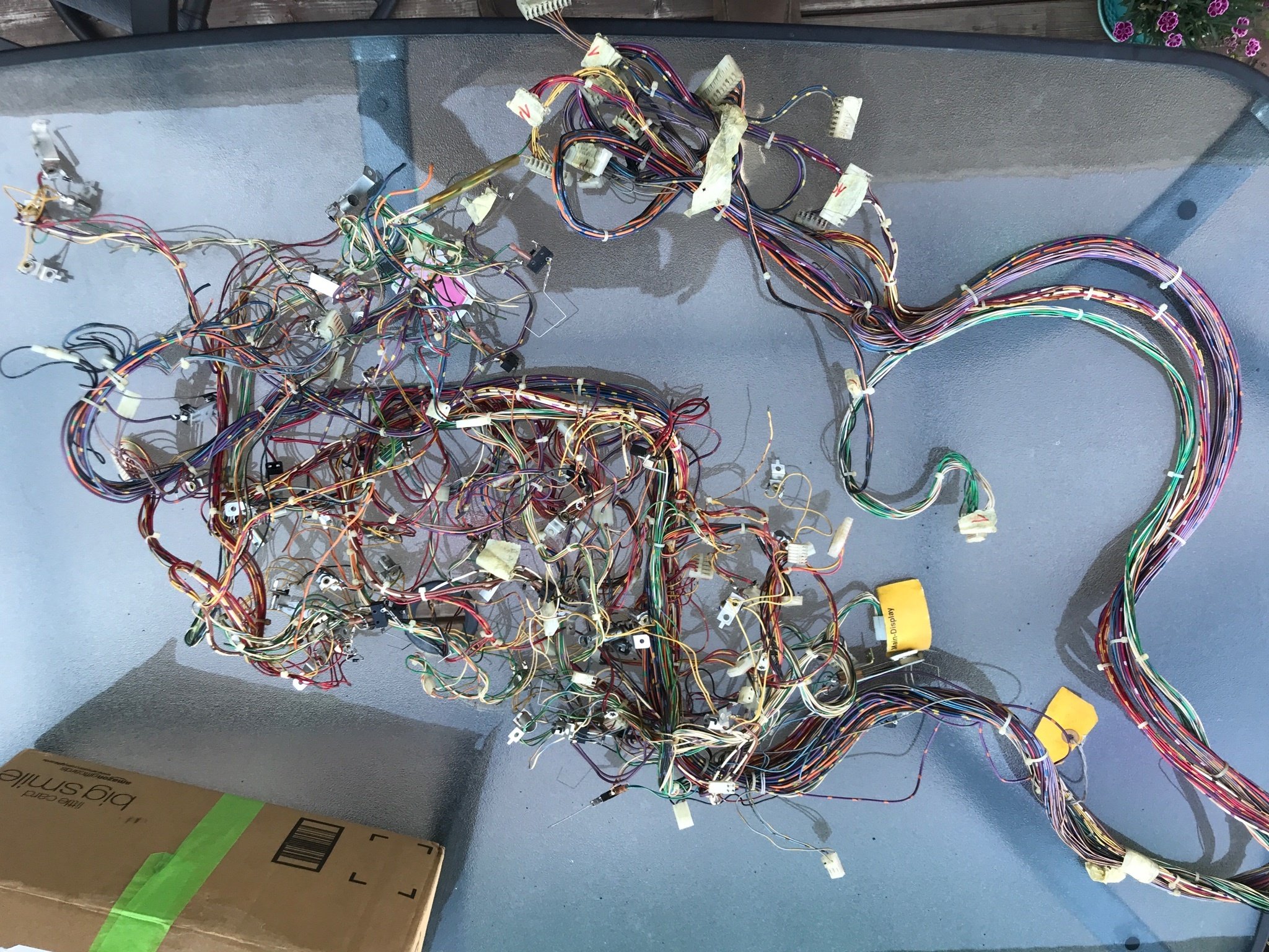
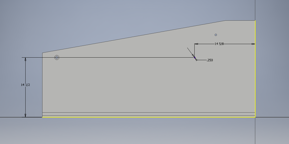