(Topic ID: 153499)

A-12742 multiple ground shorts

By fattmatt1972

8 years ago


Topic Heartbeat

Topic Stats

  • 30 posts
  • 4 Pinsiders participating
  • Latest reply 8 years ago by zaza
  • Topic is favorited by 2 Pinsiders

You

Linked Games

No games have been linked to this topic.

    Topic Gallery

    View topic image gallery

    U13_1-19.gif
    CPU_zaz.png
    first_1_(resized).jpg
    second_2_(resized).jpg
    third_3_(resized).jpg
    IMG_20160412_215145873_(resized).jpg
    IMG_20160302_240017057_(resized).jpg
    IMG_20160301_235837093_(resized).jpg
    3_(resized).jpg
    2_(resized).jpg
    1_(resized).jpg
    #1 8 years ago

    Hello everyone.

    I have a problem with an A-12742 MPU that came out of an Indiana Jones and I am hoping someone here can help me out.

    When it was in the machine the vol + and the enter button were not working.
    Also row 5 column 1 (left outlane on Indy) was permanently closed.

    There was fairly extensive battery acid damage so I replaced U16 and that fixed the vol+ and the enter button.

    I then replaced U20 to try to fix the row 5 column 1 problem.
    That did not fix it so I worked backwards and replaced U18, U19, U13 and U14, testing after each chip.

    I have removed the row 5 column 1 problem but now it shows ground shorts on row 1,2 and 3.

    I am at a loss.
    I have put sockets on everything and even with U20, U13, U14, U18 and U19 not in the sockets the game still shows the ground shorts on row 1,2 and 3.

    I swapped out another board and put it in Indy and it works fine, which also confirms there was no driver board problems causing it.

    When I am testing I only have J205 connected.

    What should I be looking at next?

    Any help would be much appreciated, I don't want to chuck the board.

    Matt.

    #2 8 years ago

    I'm sure the experts here will want to see photos of the board showing the extent of the acid damage.

    #3 8 years ago

    ...and the solder work. Hi-res photos of both sides of the board.

    This is why it is highly suggested not to shotgun problems.

    #4 8 years ago

    I am off to work now but I will take some high res photos when I get home and put them up.

    The thing that is confusing me is with all those chips removed I am still getting ground shorts.
    From what I can see the circuitry before U20 is no where near the acid damage and it all looks clean.

    Matt.

    #5 8 years ago

    The game doesn't know if there's a ground short or not. All of the rows are pulled high by resistors and if any of those rows read low then the system surmises you may have a ground short. So while a short in the row will cause the error the system not seeing 12 volts on the row for other reasons (board problem for example) will also cause the error.

    My guess would be that after all of that work you've lifted some traces or destroyed some pads/through-holes. Thus the cpu won't see 12 volts on the row and will report the error. On a board with heavy alkaline damage it's almost impossible for even a pro to pull chips w/o doing damage. It's much easier to troubleshoot and fix though if you catch it before the new chip or socket is installed.

    This is not directed at the OP, but for those reading that haven't learned this lesson the hard way: don't shotgun stuff since you'll more than likely compound the issue. The switch matrix is very easy to troubleshoot with a logic probe. Especially don't do this on an alkaline damaged board since the alkaline gets under the copper and eats away at the glue attaching it to the board. Traces and pads are already half-off before you even start soldering.

    A heavily damaged board should really be sent out to one of the board guys; whatever amount of damage you see there's four times that much hidden under IC's and other places, and they will know where to look. I've had boards where if I lightly pulled on the resistor leads they would separate from the resistor. There's really just a lot of stuff to check on battery damaged board.

    #6 8 years ago

    Hello Terry.

    I have just gotten home and I think I will have another play with this board.

    I am sure I checked all my traces and through holes because I am fairly meticulous with that sort of thing being an electrician (don't say it).
    I will pull the chips and start to continuity check all the traces to make sure I have not missed anything.
    I might pull the resistors too and give the area a good check over again.

    I will put some pics up of the board once I have removed my nail polish (off the board, lol), the chips and resistors so you can see whats going on.

    Just out of curiosity I have always used nail polish to re-insulate my traces after sanding and cleaning, opinions??

    Matt.

    Edit- Yes I always let the nail polish dry before I attempt to power up the board.

    #7 8 years ago

    Terry, I just saw you battery corrosion post and I think I need to do more checking.
    I didn't dig as deep as you have explained, I may need to remove more resistors that I thought looked ok but may not be.

    I actually have a pic or two before I started work on the board.
    I will put them up now, res might not be that great but it will give you and idea.

    Oh I forgot to say, this board had had previous work done to it.

    Matt.

    #8 8 years ago
    Quoted from fattmatt1972:

    I will pull the chips and start to continuity check all the traces to make sure I have not missed anything.

    Make sure you check the through-holes for connectivity from one side of the board to the other.

    A lot of people use nail polish and I don't see any problem with that. I use glass paint (see my soldering guide--I think I covered that) to match the solder mask color since my customers in my non-pinball day job like pretty boards. Personally I would otherwise use conformal coating since you can still solder the joint without removing it first; it melts at soldering temperatures.

    In any case I would try to keep the protective coating off of the joints. The conformal coating just gives you a little more leeway.

    I don't pull resistors unless I can't reflow the solder on the joint. I do though go along and put a pointed solder pick under every lead and pry up slightly. You would be surprised how many will break loose if there's much alkaline damage. It's also really fast just to run your loads down a row of resistors and check their resistance.

    #9 8 years ago

    Here are the before pics.
    And U16 was already in a socket too.(I redid it after these pics)

    Matt.

    1_(resized).jpg1_(resized).jpg
    2_(resized).jpg2_(resized).jpg
    3_(resized).jpg3_(resized).jpg

    #10 8 years ago

    Ok, I have some better res pics.

    I have now removed all my previous work (except the sockets on U13 and U14) and I do see a few broken traces that I MAY have missed before but I am not sure.
    There are the obvious ones which I had stitched before which are now un-stitched due to desoldering everything again.

    I did continuity check all the sockets one by one as I soldered them in but who knows, I was rushing a bit and pissed off by then..

    The board was thoroughly cleaned below the battery holder with a stiff toothbrush and vinegar prior to my first solder job on it.

    I will now solder back in all my sockets and continuity check each one as I go.
    Then the resistors in the same fashion.

    Hopefully it all works after that....

    I just noticed I bent a few pins on the connectors when I cleaned it, not bad, all good now.

    IMG_20160301_235837093_(resized).jpgIMG_20160301_235837093_(resized).jpg

    IMG_20160302_240017057_(resized).jpgIMG_20160302_240017057_(resized).jpg

    #11 8 years ago

    The alkaline damage treatment you did looks good.

    I will admit this is being picky (and probably not a functionality issue), but the joints on the four resistors below the R27 label look pretty dull (corroded). I would hit them with a fiberglass pen, add some flux to both sides of the board and see if you can reflow the solder. If you can't (again being picky) I would pull them, clean the area and install new resistors. Or you can just ignore me.

    #12 8 years ago

    Thanks for the thumbs up Terry.
    I was pondering pulling those resistors and I will now for sure.

    I also printed enlarged pics of the traces to make it easier to check them after I solder each component back in.
    It will save me opening up the bloody huge fold out schematic which has print too small to read for my crap eyes

    Matt.

    1 month later
    #13 8 years ago

    Hi again.
    I have had a bit more time to investigate the multiple row ground short problem and now I am even more confused.
    I'm hoping someone can make sense of my problem or at least guide me a little further into diagnosing what the heck is wrong with this thing.
    The board is on the bench.
    In the machine it showed ground shorts on row 1,2 and 4.
    Direct switches all OK.

    The board has been checked again for continuity between everything downstream from u12 and it's all good.

    I have used a scope and I have a pulsing signal on all 8 of the outputs of u20, and the inverted pulsing signal on all 8 the inputs.
    All 8 inputs pulses can be seen back at u14 and all 8 output pulses can be seen at j206/j207.
    The first picture is the input signal and the second picture is the output signal.
    So the column drive section must be OK?

    When I use the diode test lead to pulse each column driver to each switch row the associated signals are all present at u18 and u19, the same as in the second picture.
    The pulses can then be seen on the other side of u18 and u19 and the same pulses back at u13, seen in picture 3.

    Been that the direct switches and column drivers seen ok and the direct switches work when the board is installed then it's it safe to assume the data lines are OK?
    The data lines have no idea how to test properly.

    So basically I have all the same readings and measurements on the working and non working rows.

    Hope someone can help me where to look next, I'm stumped.

    Cheers.

    third_3_(resized).jpgthird_3_(resized).jpg
    second_2_(resized).jpgsecond_2_(resized).jpg
    first_1_(resized).jpgfirst_1_(resized).jpg

    #14 8 years ago

    I think you mixed up U14 and U13. try this one:

    (1) connect a wire from one column drive to all 8 inputs of J208/209
    (2) measure the 8 outputs of the LM339, they should be pulsing
    (3) same signal should enter the inputs at U13, measure them too.

    CPU_zaz.pngCPU_zaz.png

    #15 8 years ago

    Corrected, I just wrote u14, not u13, thanks for picking that up.

    No mix up though, that is the same diagram I used and all the readings are as they should be.
    Hence the confusion.

    Where do I look next?

    Matt.

    #16 8 years ago

    Remove all connectors from J205-J209 and J212, power up the CPU-board.
    Do you measure 5 Volt at all red marked pins of U13 ? (pin 2,4,6,8,11,13,15,17)

    #17 8 years ago

    Hi zaza, yes I have 5v at all of those pins on u13.
    2,4,6,8,11,13,15 and 17.
    Same voltages as where they leave u18 and u19.

    And the board is out of the machine on the bench too, not in the machine.

    Thanks for the help.
    Matt.

    #18 8 years ago

    do I understand correct:
    -With CPU in the machine and no switch inputs connected (on J205-J212) still give row short 1+2+4 , also when U13 is out of socket ?
    -There is continuity from D0-D7 U13 to D0-D7 U12, measured on IC pins
    -The pull-up resistors are connected and working because you measured 5Volt at U13 inputs 1-8.

    #19 8 years ago

    With CPU in machine and j205- j212 disconnected I get ground row short 1,2 and 4, tick.
    With u13 out I have not tried, I will check..

    Continuity on all data lines between u12 and u13, tick.
    5v at all inputs on u13, tick.

    Thanks for helping me through this, much appreciated.

    Next idea?

    Cheers,
    Matt.

    #20 8 years ago

    If machine detects a 'ground row short' at row 1,2,4 and the inputs at U13 are Hi-level, all data lines are ok, all (8) direct switch are ok, then my last idea would be to try a new 74LS240 for U13.

    #21 8 years ago

    I have a few LS240's and already tried a new one in u13 with no luck, 2 actually.

    Now you see why I'm stumped, nothing makes sense to me.

    Matt.

    #22 8 years ago

    Is there continuity between pin 1 and pin 19 of U13 ? this IC has 2 separate enables (but that wouldn't explain why row 3 has no problem).

    #23 8 years ago

    I will check that.

    I'm just out atm but I'm home later.

    Cheers.
    Matt.

    #24 8 years ago

    Sascha, you my friend are a legend!

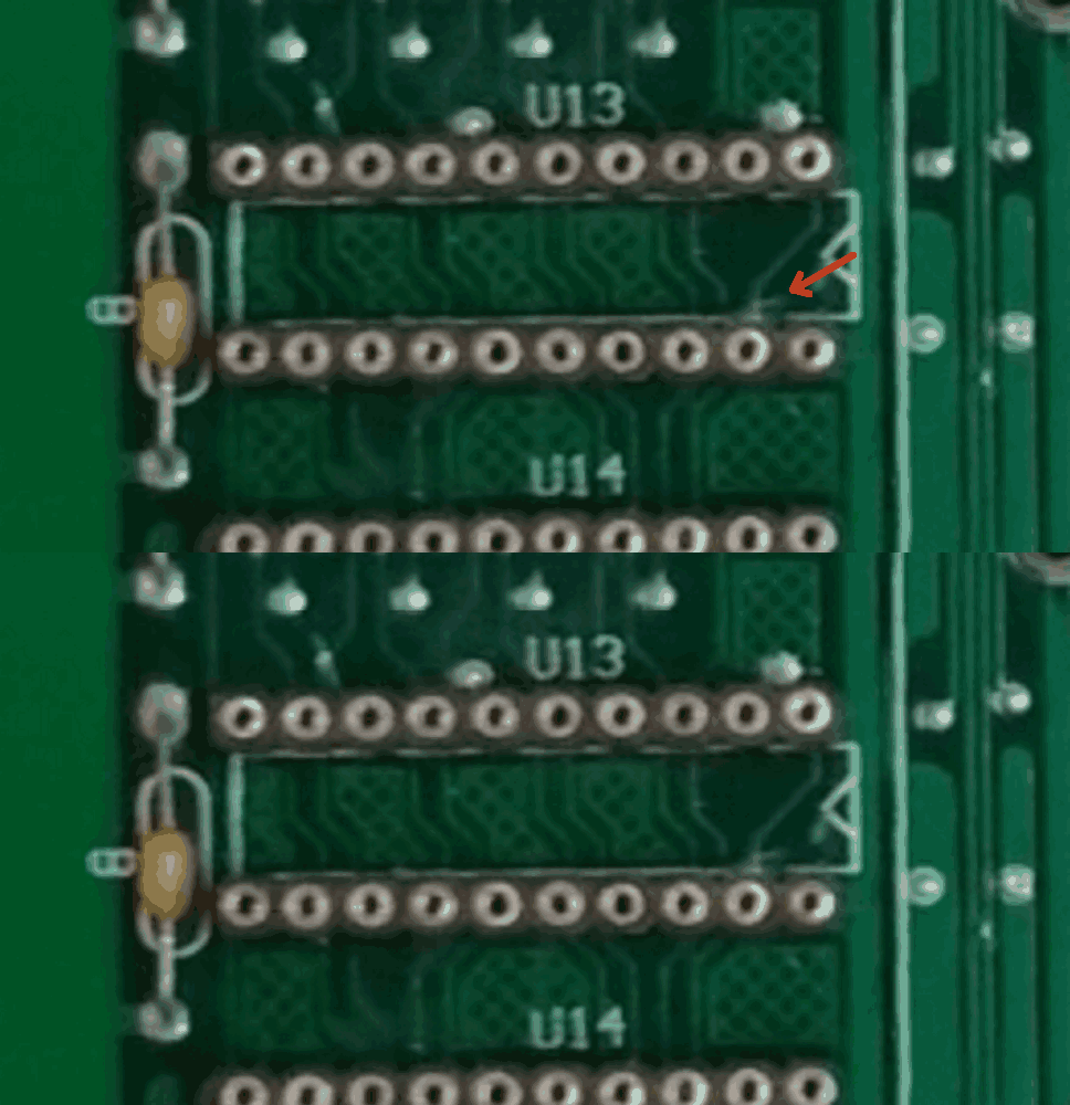
    It was a tiny crack in the trace between pin 1 and pin 19 of U13.

    I fixed it and voila, no more ground shorts.
    It was honestly the only trace I did not check, and it bit me in the backside.

    If you look at the pic I posted earlier in the thread you can actually see the damage just above pin 19.

    Again, thank you so much for your help (and diagram) Sascha and thanks to Terry for his earlier help, you guys rock.

    Matt.

    #25 8 years ago

    applause for all !
    Glad you found it because this was the last thing I could come up with.

    Sascha

    edit:

    Quoted from fattmatt1972:

    If you look at the pic I posted earlier in the thread you can actually see the damage just above pin 19.

    Yes, I see what you mean:
    U13_1-19.gifU13_1-19.gif

    #26 8 years ago

    I still have not done a full physical switch test in the machine, just installed the board and turned it on and just the time/date message (no batteries installed yet)
    Went into switch test mode too and no unexpected closed switches.

    I will test fully tomorrow but I think it's good.

    The only thing bothering me, and I will find out tomorrow when I test..
    Why was row 3 not shorted like 1,2 and 4.

    As you said this makes no sense as they are on the same side of u13, and I like things to be logical and make sense, any ideas??

    EDIT- I know they weren't actually shorted but that is just the terminology I use, probably shouldn't as it can be confusing I guess.

    Matt.

    #27 8 years ago

    Nice flashing arrow!

    Yep, that was the culprit.

    Matt.

    #28 8 years ago
    Quoted from fattmatt1972:

    The only thing bothering me, and I will find out tomorrow when I test..
    Why was row 3 not shorted like 1,2 and 4.

    I don't know, row 2 and 3 look identical to me in the tech-chart with some mechanical and optical switches combined.

    #29 8 years ago

    I will test it fully tomorrow and hopefully not have to report back here

    Thanks again Sascha.

    By the way, you any good with Stern driver boards?
    I was working on a 520-5137-00 rev.G from a playboy and I had a few strange things with it too.
    I hate this board and the associated schematics, they suck balls.
    I think I will re attack this again next, it has been on the to do list for a while..

    I will start another thread soon, feel free to chime in if you want, would be much appreciated.

    Matt.

    #30 8 years ago
    Quoted from fattmatt1972:

    By the way, you any good with Stern driver boards?

    No, not really. I've no schematics / boards / machines around to test or check. Maybe after I fully understand WPC I'll dive into other systems but that is still far away.

    Reply

    Wanna join the discussion? Please sign in to reply to this topic.

    Hey there! Welcome to Pinside!

    Donate to Pinside

    Great to see you're enjoying Pinside! Did you know Pinside is able to run without any 3rd-party banners or ads, thanks to the support from our visitors? Please consider a donation to Pinside and get anext to your username to show for it! Or better yet, subscribe to Pinside+!


    This page was printed from https://pinside.com/pinball/forum/topic/a-12742-multipleground-shorts and we tried optimising it for printing. Some page elements may have been deliberately hidden.

    Scan the QR code on the left to jump to the URL this document was printed from.