(Topic ID: 306609)

69Volts Gottlieb System 1

By Kickout

2 years ago


Topic Heartbeat

Topic Stats

  • 18 posts
  • 6 Pinsiders participating
  • Latest reply 2 years ago by Cheddar
  • Topic is favorited by 1 Pinsider

You

Linked Games

Topic Gallery

View topic image gallery

pasted_image (resized).png
#1 2 years ago

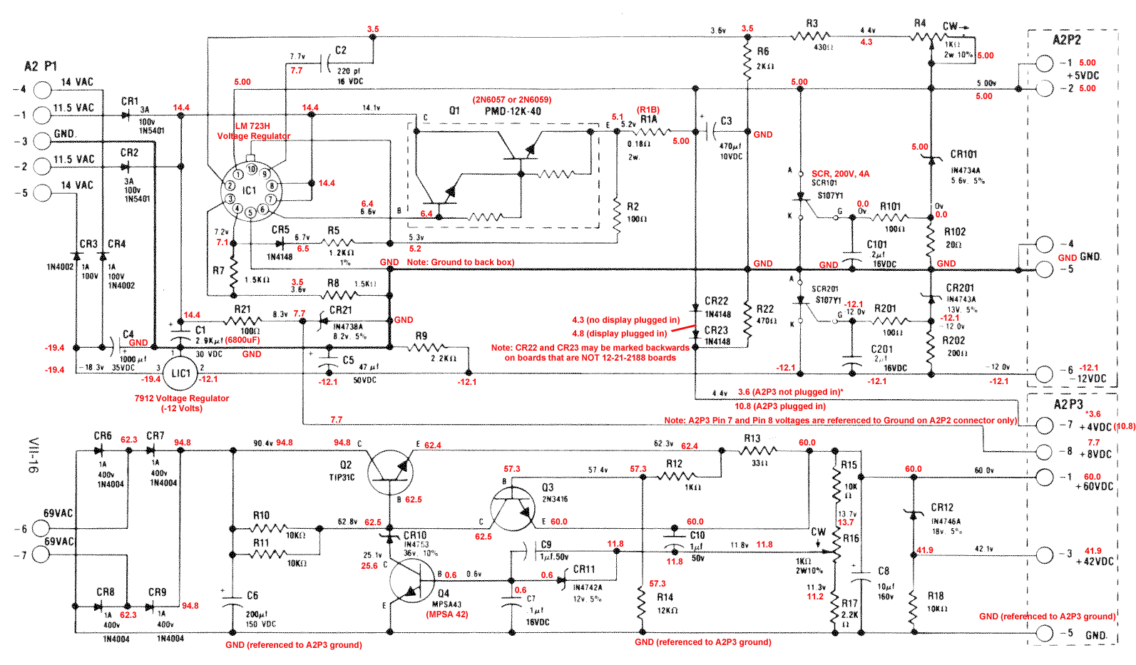
Just picked up a Close Encounter of the Third Kind that has been sitting in a basement for quite a while. Over all the cabinet, playfield and back glass are all in great shape. Tested the bridge rectifiers and replaced all fuses. Following the guide for testing the system 1 AC power at A2, here are my AC results.

A2-P1 pin 1 = 11.5 volts AC
A2-P1 pin 2 = 11.5 volts AC
A2-P1 pin 3 = common (ground, black)
A2-P1 pin 4 = 14 volts AC
A2-P1 pin 5 = 14 volts AC
A2-P1 pin 6 = 23 - 48 volts AC
A2-P1 pin 7 = 23 - 48 volts AC

The last two pins are not showing the 69 volts. Planning on replacing C1 at 2900 mfd with a new 6800 mfd to 10,000 mfd filter capacitor. Also doing the ground mods. Don't know if this will help with the 69 volts, but it's recommended. What should I be doing besides this to get the correct voltage.

Thanks
Kickout

#2 2 years ago

Are you measuring between pin 6+7? What does the range of voltages mean?

#3 2 years ago

Here's how I do it
Set DMM to VAC
Turn Machine On
Black to Ground
Red to J1 Pin 1 & 2 ~12 VAC
Red to J1 Pin4 & 5 ~14 VAC
Black to J1 Pin 6
Red to J1 Pin 7 ~69 VAC
Turn Machine Off

#4 2 years ago

Cheddar,

Tested the method you used and got the following
Pin 1 & 2 ~12.7 VAC
Pin4 & 5 ~14.3 VAC
Black to J1 Pin 6
Pin 7 ~76 VAC

does this seem correct?

#5 2 years ago
Quoted from Kickout:

Cheddar,
Tested the method you used and got the following
Pin 1 & 2 ~12.7 VAC
Pin4 & 5 ~14.3 VAC
Black to J1 Pin 6
Pin 7 ~76 VAC
does this seem correct?

yes it does. they will run a little high without load

#6 2 years ago

Cheddar,

Thanks, now on to the second part of testing the power supply the other connectors.

#7 2 years ago

Ok, step 2 of power supply test. Have correct voltages on A2-P1 and A2-P2.

On A2-P3 the voltages on
A2-P3 pin 7 = +4 volts DC reads 0.7
A2-P3 pin 8 = +8 volts DC reads 0.7

Connect A2-P2 to CPU A1-J1
At C-16 reads are 0.7
At C-17 reads are 11.7

Here's where I am, now what should I be doing? Hope you experts can give me some advice.

Thanks
Kickout

#8 2 years ago

Isn't there a potentiometer to dial in the voltage level?

#9 2 years ago

Test Q2,Q3,& Q4 for the proper 2 junctions on each transistor.

#10 2 years ago

Pinballdaveh,

Quoted from pinballdaveh:

Test Q2,Q3,& Q4 for the proper 2 junctions on each transistor.

Do i have to take these off the board to test them?

#11 2 years ago

The Q2 transistor that’s heat sinked to the frame will have it’s leads poking thru the board. The other 2 transistors can be tested if theres enough room for the leads to touch transistor wires. The 2 junctions in each transistor should read close to the same at 7-15 ohms is common.
Sometimes in circuit test results may vary due to other components in the circuit.

#12 2 years ago
Quoted from Kickout:

Ok, step 2 of power supply test. Have correct voltages on A2-P1 and A2-P2.
On A2-P3 the voltages on
A2-P3 pin 7 = +4 volts DC reads 0.7
A2-P3 pin 8 = +8 volts DC reads 0.7
Connect A2-P2 to CPU A1-J1
At C-16 reads are 0.7
At C-17 reads are 11.7
Here's where I am, now what should I be doing? Hope you experts can give me some advice.
Thanks
Kickout

I wasn’t sure from your description, but
+4 and +8 are measured with respect to the ground on A2P2 (pins 4,5).
Apologies if you are already doing this. It does get confusing with the 2 different grounds.
Those 2 voltages come from different sources, so I’m scratching my head too

Dave

1 week later
#13 2 years ago

Ok here are my readings when testing the power supply board. What should I be doing to correct the missing voltages?

A2-P1/J1
A2-P1 pin 1 = 12.5 volts AC
A2-P1 pin 2 = 12.5volts AC
A2-P1 pin 3 = common (ground, black)
A2-P1 pin 4 = 15.1 volts AC
A2-P1 pin 5 = 15.1 volts AC
A2-P1 pin 6 = 35.5 volts AC
A2-P1 pin 7 = 35.5 volts AC

A2-P2/J2
A2-P2 pins 1,2 = .0 volts DC, potentiometer adjusted to full power.
A2-P3 pin 3 = Key
A2-P2 pins 4,5 = Ground
A2-P2 pin 6 = -11.9 volts DC

A2-P3/J3
A2-P3 pin 1 = 62 volts DC
A2-P3 pin 2 = Key
A2-P3 pin 3 = 45volts DC
A2-P3 pin 4 = not used
A2-P3 pin 5 = Ground
A2-P3 pin 6 = not used
A2-P3 pin 7 = +0 volts DC
A2-P3 pin 8 = +0 volts DC

#14 2 years ago

A2P2 is the 5VDC right? Use this schematic and work your way back to the regulator. You can see where the genius who made this schematic (not me) put in the expected voltage at each point. http://www.stevechannel.com/images/tech_tips/System1PowerSupplySchematic.jpg

You might find that it is correct at 1 point and then bad at the next. That would indicate the component needs to be replaced. What I'd expect here if the regulator is putting out 5v is the SCR101 or CR101 is shorted.

#15 2 years ago

Turn the 5volt pot to its minimum setting. It might be the over voltage circuit is shutting it down. Retest, has the 4,5,& 8 dc volts outputs returned? Power supply might be in need of recapping.

1 week later
#16 2 years ago
Quoted from Cheddar:

A2P2 is the 5VDC right? Use this schematic and work your way back to the regulator. You can see where the genius who made this schematic (not me) put in the expected voltage at each point. http://www.stevechannel.com/images/tech_tips/System1PowerSupplySchematic.jpg

Correct, I will go back and check voltages from that schematics.

Quoted from pinballdaveh:

Turn the 5volt pot to its minimum setting. It might be the over voltage circuit is shutting it down.

The 5volt pot is turned up all the way.

#17 2 years ago

Rechecked the DC voltages. Missing the +5 volts at A2P2 P1 & P2. Also missing the +4 volts at A2P3 P7. Looking at the schematic it looks to me that these voltages are all supplied by related parts on the board. Any help determining which parts I should be looking at is helpful.

Thanks
Kickout

#18 2 years ago
Quoted from Kickout:

Correct, I will go back and check voltages from that schematics.

The 5volt pot is turned up all the way.

Turn it down. The worry is it's too high and the protection circuit is pulling to to ground to protect the mpu.

Quoted from Kickout:

Rechecked the DC voltages. Missing the +5 volts at A2P2 P1 & P2. Also missing the +4 volts at A2P3 P7. Looking at the schematic it looks to me that these voltages are all supplied by related parts on the board. Any help determining which parts I should be looking at is helpful.
Thanks
Kickout

After you turn down the 5V you have to work backwards from A2P2 P1 and test at all the places on the 5V line.

In the attached image I have labeled the points you can test (1 to 4 circled) and the expected VDC to see where the voltage may have dropped.
pasted_image (resized).pngpasted_image (resized).png

Work backwards from A2P2 P1 to the junction of CR101 and R4 (5V adjustment pot) and measure there. You may need to poke around with the machine off to find someplace to test. My guess would be the center lead of the pot but see if it has continuity to CR101 before you use it as a test point.

If you find you have 5V at 1 place but not the next the component closest to A2P2 is suspect.

Promoted items from Pinside Marketplace and Pinside Shops!
$ 15.00
Lighting
Space Coast Pinball
 
From: $ 4.99
Cabinet - Decals
The Pinball Scientist
 
Wanted
Wanted
Hey modders!
Your shop name here

Reply

Wanna join the discussion? Please sign in to reply to this topic.

Hey there! Welcome to Pinside!

Donate to Pinside

Great to see you're enjoying Pinside! Did you know Pinside is able to run without any 3rd-party banners or ads, thanks to the support from our visitors? Please consider a donation to Pinside and get anext to your username to show for it! Or better yet, subscribe to Pinside+!


This page was printed from https://pinside.com/pinball/forum/topic/69volts-gottlieb-system-1?hl=kickout and we tried optimising it for printing. Some page elements may have been deliberately hidden.

Scan the QR code on the left to jump to the URL this document was printed from.