(Topic ID: 89748)

1987 Data East Laser War Topper?

By LesManley

9 years ago


Topic Heartbeat

Topic Stats

You

Linked Games

Topic Gallery

View topic image gallery

Screenshot_20220126-165747_Video Player.jpg
20220126_165308_1.gif
20220120_183759 (resized).jpg
20220120_164836 (resized).jpg
20220120_165635 (resized).jpg
20220120_165622 (resized).jpg
20220120_165605 (resized).jpg
20220120_163915 (resized).jpg
20220120_165746 (resized).jpg
20220120_165722 (resized).jpg
pintastic_2021_12 (resized).jpg
Lyte 2022 (resized).jpg
20220112_180020 (resized).jpg
20220112_175936 (resized).jpg
20220112_175917 (resized).jpg
20220112_180053 (resized).jpg

Topic index (key posts)

7 key posts have been marked in this topic (Show topic index)

There are 182 posts in this topic. You are on page 2 of 4.
#51 6 years ago

This seems like a major breakthrough. I know we've all seen the topper on the flyer, but is this the first time we've known that the product is actually called "Lyte?"

You know some shop in some small town is sitting on a hoard of NOS Lyte boxes. Not the official topper ones, but the actual product. Seems like it shouldn't be that hard to convert it to something that looks like the LaserWar topper.

#52 6 years ago

I knew it had "lyte" was associated with it, but until now, I thought it was the manufacturer rather than the product name, as per the comment from Joe Kaminkow on IPDB. It's tough to find something named "lyte" without another piece of identifying information. Clyde combined with Lyte was the key.

Quoted from woody24:

Seems like it shouldn't be that hard to convert it to something that looks like the LaserWar topper.

You would still have to make a vacuform mold for the data east style box, and find some smoked glass to cut to the right shape to fit the box. It looks like the glass is riveted to the case.

There's also what looks like holes on the side (in the laser war flyer), and I'm not sure what those are for.

On IPDB:

The manufacturer flyer shows a trapezoidal backbox topper with a spinning red LED board to create an optical effect. Joe Kaminkow told us that the light itself came in a square black box, approximately 12 by 12 inches, made by a now-defunct company called Lyte. Data East added a custom trapezoidal housing around it for mounting on the backbox using screws. The spinning LED display did not operate in concert with game play. He wasn't sure if it got its power from 12 volts from the output of the sound board or if it had a 110v line cord. Joe said the topper was too expensive and was discontinued during the production run of this game. He guessed about 500 of the earliest machines came with this topper.

So, a few pieces of info in that comment are incorrect at least--the Lyte name, and the number of them made (I keep hearing the number 10 thrown about--not 500).

Also, it seems odd that the device would not be connected to the sound system in some way considering it is a sound visualizer (and that this was the first stereo sound system). I really want to see if @aberdeentp's topper has a cord that would connect to something in the game.

#53 6 years ago
Quoted from aberdeentp:

I just found this post, I have this topper, a friend found it in the depths of the warehouse of the Game Exchange in Denver, they had it for years but guess they never got a game to put it on. So he negotiated a price for me and it's on my Laser War. I doubt there is enough interest to warrant a reproduction but if anyone decides to I can try to help anyway I can. It does work, and does all kinds of tricks, I imagine it would be better in a darkened room.

Quoted from aberdeentp:

here's a picture

Id buy a repro kit. Send the box to freeplay 40 to redo the plastic and post pics of the insides

Id also help with this project as well

#54 6 years ago
Quoted from lordloss:

Id buy a repro kit. Send the box to freeplay 40 to redo the plastic and post pics of the insides
Id also help with this project as well

Realistically, what would happen would be this:

Plastic shroud is made/formed.
Donor LYTE system is bought off ebay
Convert donor lyte to fit Data East topper plastic.

The only LYTE on ebay was bought within minutes after the post was made..

#55 6 years ago
Quoted from lordloss:

The only LYTE on ebay was bought within minutes after the post was made..

Yeah, that was me. I figured it would be better for a pinhead to lay hands on it to potentially have a shot a documenting and reproducing it. It seems like it could be an interesting project to tackle.

#56 6 years ago
Quoted from ForceFlow:

Yeah, that was me. I figured it would be better for a pinhead to lay hands on it to potentially have a shot a documenting and reproducing it. It seems like it could be an interesting project to tackle.

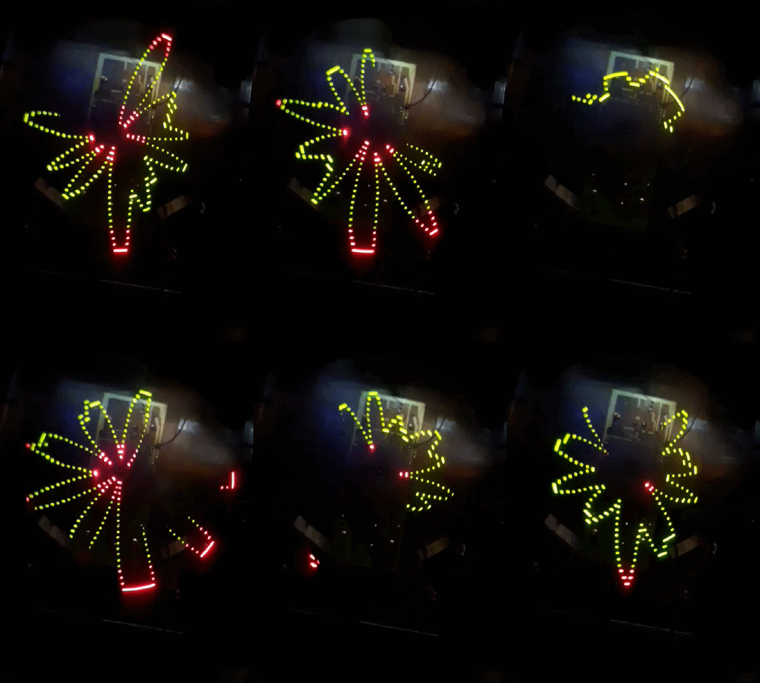
Glad to hear you got it. That's why I posted the link here

The missing piece here seems to be how the "Lyte" gets a signal from the machine, assuming the off the shelf Lyte is the same as the topper version.

#57 6 years ago
Quoted from Clnilsen:

The missing piece here seems to be how the "Lyte" gets a signal from the machine, assuming the off the shelf Lyte is the same as the topper version.

Well, as long as you can grab an unamplified audio signal from somewhere, you should be able to connect it to the lyte's input.

The amplified output to the speakers would probably blow the lyte's board.

#58 6 years ago

3 years and finally confirmation with a physical topper. Nice. My Laser War is long gone, I thought for sure that we'd find Bigfoot or the Loch Ness Monster before one of these would actually show up. Really cool.

#59 6 years ago
Quoted from LesManley:

3 years and finally confirmation with a physical topper. Nice. My Laser War is long gone, I thought for sure that we'd find Bigfoot or the Loch Ness Monster before one of these would actually show up. Really cool.

Did that stay in MN? I wouldn't mind a laser war to complete my DE set someday.

#60 6 years ago
Quoted from lordloss:

Did that stay in MN? I wouldn't mind a laser war to complete my DE set someday.

No, it went off to the unholy land just east of us.

#61 6 years ago
Quoted from LesManley:

No, it went off to the unholy land just east of us.

I'll live without. ;(

#62 6 years ago

ok, well I'll try to do what I can soon, I'm up to my neck getting my taxes ready and with work, but I promise I will get to this.

#63 6 years ago

tomorrow my goal is to get some pictures taken and loaded, but I'm an old 8 bit lo fi type, think basic saw wave, and never posted a video on you tube or anywhere, so once I shoot a video with my phone don't know how to upload it.

#64 6 years ago
Quoted from aberdeentp:

tomorrow my goal is to get some pictures taken and loaded, but I'm an old 8 bit lo fi type, think basic saw wave, and never posted a video on you tube or anywhere, so once I shoot a video with my phone don't know how to upload it.

If you install the youtube app on your phone, it should make the process fairly straight forward.

10
#65 6 years ago

Here are two pictures, the video is uploading now, the other wire is going to the speaker so it would seem it is sound that causes the resulting interaction. This might not be how it was intended to be hooked up, obviously this didn't come with directions, so I don't know if it could be wired so something else generates the interaction.
here is the link for the video

20180314_175943[1] (resized).jpg20180314_175943[1] (resized).jpg

20180314_180906[1] (resized).jpg20180314_180906[1] (resized).jpg

#66 6 years ago

Thanks for posting--that looks cool. Never thought I'd see one of those in action.

I'm surprised that it's connected to the amplified output. I wonder if they did anything special inside the unit to account for that.

#67 6 years ago

I got my lyte box today. It was missing the power adapter, so I wasn't able to power it up. But, I did take it apart to see what was inside.

Nothing too surprising, and more or less what I was expecting to see since most of the mystery was revealed in other photos of the spinning LED board.

There are two boards in the unit. The board inside has the motor, takes power input, signal input, and the sensitivity adjustment. The board with the LEDs is mounted on a motor, and there are 3 contacts on the shaft that bring connections between the two boards.

The one downside is that the board with the LEDs was painted, so none of the part numbers/specs of the components are visible. It might be difficult to remove the paint without harming the ink for the letters & numbers.
20180314185416248 (resized).jpg20180314185416248 (resized).jpg20180314185443991 (resized).jpg20180314185443991 (resized).jpg20180314185526531 (resized).jpg20180314185526531 (resized).jpg20180314185838945 (resized).jpg20180314185838945 (resized).jpg20180314190023253 (resized).jpg20180314190023253 (resized).jpg20180314190218285 (resized).jpg20180314190218285 (resized).jpg20180314190251800 (resized).jpg20180314190251800 (resized).jpg20180314190734265 (resized).jpg20180314190734265 (resized).jpg

#68 6 years ago

Seeing the pictures of it and the rotary finger contacts reminds of something i saw in my younger years spinning speakers on a organ at a house. If my memory is right they were Leslie gyro sonic speakers or leslie like. As far as the paint issue you could do a test spot on corner of board long as there are no traces there to ruin. Looks like they did a got job of painting it.

#69 6 years ago

This thing is cool! My buddy's Laser War needs one. Put me on the list if someone can remake it and I'll buy it for him.

Thanks for all the work going into this

1 week later
#70 6 years ago

Which one of you guys beat me to the second LYTE on ebay yesterday?

2 months later
#71 5 years ago

I ended up finding another one, and this one appears to be a later version than the one I posted about earlier. It has significantly less circuitry & components than the original one, so they simplified the device quite a bit.

20180526200516267 (resized).jpg20180526200516267 (resized).jpg20180526200642388 (resized).jpg20180526200642388 (resized).jpg20180526200719506 (resized).jpg20180526200719506 (resized).jpg20180526200734809 (resized).jpg20180526200734809 (resized).jpg20180526200930192 (resized).jpg20180526200930192 (resized).jpg20180526200955663 (resized).jpg20180526200955663 (resized).jpg
#72 5 years ago

What little I can determine is that there was an 80 LED version, and a 20 LED version. Which one is appropriate for laser war, I haven't got a clue.
I've never even played the game but something drew me to click this thread, and now I'm hooked.

However, I think I know how it works, and I'd bet dollars to donuts I have a datasheet for the IC's in front of me.
For some reason I saw one of these IC's at work and was convinced I needed to keep the info fresh in my brain.

The hard part will actually be the interconnect between the LED board and the motor board.

#73 5 years ago
Quoted from ForceFlow:

I ended up finding another one, and this one appears to be a later version than the one I posted about earlier. It has significantly less circuitry & components than the original one, so they simplified the device quite a bit.

And not all blacked out!!

Do you know if it functions the same??

Any chance of starting a component list and sketching schematic???

#74 5 years ago

My guess looking at still shots of the running game, it has the 20 light version. I can do most of the schematic of the LED board easily, only question will be the resistor values. Both versions likely work the same just with a lot more lights in the bigger version.

If I had a photo of both sides of the motor board and I could probably get that too. But that's not the critical piece here.

#75 5 years ago
Quoted from pacmanretro:

And not all blacked out!!
Do you know if it functions the same??
Any chance of starting a component list and sketching schematic???

Idk what I was thinking...just noticed front side of pcb is still blacked out

Hopefully we can get the info still underneath??

#76 5 years ago
Quoted from pacmanretro:

Idk what I was thinking...just noticed front side of pcb is still blacked out
Hopefully we can get the info still underneath??

I gotcha covered. I’m 95% sure I know what those two IC’s are.

That IC has multiple ways it can be integrated to do lighting displays. Trying to pick out which way it's done. Starting work on a schematic already, and the more I work on on it, the more I'm convinced I have the right one. The trick is going to be I have zero clue on the values of the resistors and capacitors on the LED board. That and I would need to see the back sides of both boards to trace things out.

-Hans

#77 5 years ago

I have too many things brewing right now to pursue any kind of a repro on these boards, and zero ability to do a housing for it.
But this partial schematic should give a good leg up for anybody else that may want to take it on.
Doesn't mean I won't keep an eye on things and chime in as I can help.
Oddball research projects like these are just too fun for me sometimes.

The IC's used for both locations U1 and U2 on these I'm about 99.9% positive is an LM3914. Was very commonly used for LED bar graphs in things like graphic equalizers, Vu meters, voltage meters, and things like that back in the 80's. As soon as I saw how this operated, I knew this was the likely culprit. If I'm not going to be making them myself, there's no reason not to share the info. The more I dug through building a schematic, the more it all lined up perfectly. These IC's are still readily available either in SMT or thru-hole and not expensive.

The other critical piece you'll need is called a 3-wire slip joint. This is the three-wire connection between the motor board and the LED board. Lots of places out there to get them, but I don't know how fast you need to spin, so be careful of the cheap 250rpm versions out there. The three wires coming through are LED voltage, Signal, and Ground, as best I can tell. Not something I've worked before but I did know the name at least.

Motor board I'm not going to really dig into very much as the photos should be a very good start to reverse engineer things. All the parts are clear and easy to see, and from the various photos so are the traces. Generic transistor, voltage regulator, and op-amp. The only tricky part will be nailing down the value on the pot and the speed of the motor.

The slip joint, along with the housing, are going to be your major factors on price.
I don't expect this to be a cheap repro by any means.

Can't quite figure out a couple components on the LED board from the photo for a schematic.
No idea at all where the signal line from Pin2 on the slip joint goes.
Also can't trace the lines from R1, R4 and R5 completely around U2.
The two IC's do have different circuits so can't just copy.

I'm also not 100% certain how R7-R10 and C2-C5 really are, so definitely verify those if possible.

Won't be able to know the resistor values without seeing the stripes (which may be visible from a low side angle).
Multimeter can't always get you values if you measure in-circuit.

I am confused over which version Laser War had in it.
Pausing the youtube video suggests the 20-LED version.
Some of the older promotional photos LOOK like the 80-LED, but that could just be ISO/Shutter settings being tricky.
However, that old Worthpoint link to the EBAY photos? That appears to be a third version completely.
I wonder if they may have made games with all three (known) versions of the Lyte.
There may not be a 'correct' version. Too little data points here.

-Hans

Lyte Interim Schematic.pdfLyte Interim Schematic.pdf
LYTE 20LED (resized).jpgLYTE 20LED (resized).jpg

2 months later
#78 5 years ago

I managed to recently acquire two versions of the very elusive Cylde Lyte owner's manual.

I scanned them in, and here they are. One is undated, the other is dated 1988.

Clyde Lyte Owner's Manual (1988).pdfClyde Lyte Owner's Manual (1988).pdfClyde Lyte Owner's Manual (undated).pdfClyde Lyte Owner's Manual (undated).pdf
1 year later
#79 3 years ago

Old thread I know but just picked up a Laser War and been fascinated by the topper. Not sure if this is usual for all Laser War or not but my serial number is below a thousand and the top is drilled for topper mounting holes. I'm planning on making a facsimile of the original that catches the spirit if not actual function eventually.

Attached are the screen grabs from the Worthpoint page and picture of the top of my cabinet. You can clearly see the four point mounting pattern and the single larger hole which I assume is for running the wiring into the cabinet.

ebay (resized).jpgebay (resized).jpgebay2 (resized).jpgebay2 (resized).jpg

20200503_075034 (resized).jpg20200503_075034 (resized).jpg

Added over 4 years ago:

5 point mounting, not four.

#80 3 years ago

Some notes from tonight's adventures in the garage...

1) The proportions look slightly wrong to me, I think it needs to be wider at the base and taller. The current one is 12" high, 12.5" wide at the top and 18.5" at the base not counting "flange". These measurements are based off cabinet picture on first page which I think are off. Picture "front view" below was sized to match my cabinet 30.25" width and other measurements extrapolated from there in Photoshop.

2) I think this is in error or perhaps there are more than one version of the topper pictured floating about. If you look at the flyer there is clearly a cutout for the key and indents for the mounting bolts which match my cabinet. The current test piece base isn't wide enough to reach these points so I'll back up and try again based of the cabinet bolt pattern.

3) Tried hard to get the right perspective on the picture to match the flyer, will take more pictures tomorrow.

4) The top I had to guess at the thickness, I picked 4". Forceflow had a Lyte unit that measured 11.5" x 11.5" x 3.5" while Clyde indicated in a flyer they were 12 x 12 x 3. At any rate either one would fit though a 12 x 12 unit would be tight which again makes me think I have to go at least another inch taller. One has to wonder what was used to secure the unit to keep it from rattling around though.
version_1 (resized).jpgversion_1 (resized).jpgLS_FLYER (resized).jpgLS_FLYER (resized).jpgebay_arrows (resized).jpgebay_arrows (resized).jpgfront view (resized).jpgfront view (resized).jpg

#81 3 years ago

Started fresh after work; after careful measuring of the cabinet and repeated views of available pictures I'm confident this base is pretty darn close. I build up from here.

20200505_182527 (resized).jpg20200505_182527 (resized).jpg20200505_182507 (resized).jpg20200505_182507 (resized).jpg
#82 3 years ago
Quoted from gdonovan:

Forceflow had a Lyte unit that measured 11.5" x 11.5" x 3.5" while Clyde indicated in a flyer they were 12 x 12 x 3.

I'm guessing they discarded the outer wooden box and did their own mount, which would have made the topper shell a bit smaller. Then they probably used a trapezoid-shaped piece of smoked plastic and riveted it to the plastic topper's shell.

#83 3 years ago
Quoted from ForceFlow:

I'm guessing they discarded the outer wooden box and did their own mount, which would have made the topper shell a bit smaller. Then they probably used a trapezoid-shaped piece of smoked plastic and riveted it to the plastic topper's shell.

Possible, I have taken all the available images and played with contrast and brightness to try and determine to no avail. I do know based on measurements that the housing is easily large enough to take the whole original assembly without being disassembled.

#84 3 years ago

I have my new numbers based off video grabs and some more photoshop tomfoolery, look for mock up 0.2 in the morning.

#85 3 years ago

Going over the available images I need to be cautious when trying to come up with anything definitive. The two toppers shown are slightly different.

If you look at the the one from the DE flyer image, there is no Data East logo visible in the top of the housing and the Lyte device has a different center offset than the one from the video. I suspect the prototype in the flyer has the earlier 12 x 12 x 3 Lyte as indicated in the Clyde flyer and the production unit has the 11.5 x 11.5 x 3.5 Lyte ForceFlow has come across.

The production housing and Lyte assembly has a bias to the bottom of the opening of about an inch where the prototype housing you can see the Lyte is mounted higher.

video grab_2 (resized).jpgvideo grab_2 (resized).jpgLS_FLYER_3 (resized).jpgLS_FLYER_3 (resized).jpg
#86 3 years ago
Quoted from gdonovan:

Going over the available images I need to be cautious when trying to come up with anything definitive. The two toppers shown are slightly different.

I would ignore the flyer and just focus on actual photos of the topper. It's not uncommon for prototype features to appear in the flyers, or for an artist to mock something up. They are promotional materials and not always reflective of what the final version of the game ends up to be.

For one thing, the Lyte does not actually display concentric circles like in the flyer. When it's receiving no audio input, there's only one circle visible.

#87 3 years ago
Quoted from ForceFlow:

For one thing, the Lyte does not actually display concentric circles like in the flyer. When it's receiving no audio input, there's only one circle visible.

Caused by shooting film with a longer exposure time I'm sure.

#88 3 years ago
Quoted from gdonovan:

Caused by shooting film with a longer exposure time I'm sure.

Maybe--seems like an odd choice and difficult photo to take, though. I would've tried to capture an active waveform. Or maybe it was just painted into the flyer.

#89 3 years ago
Quoted from ForceFlow:

Maybe--seems like an odd choice and difficult photo to take, though. I would've tried to capture an active waveform. Or maybe it was just painted into the flyer.

I suspect they were just trying to make the backglass pop a little, hence the longer exposure time which isn't uncommon when working with film as it gives the media more time to absorb light. But anything that is moving will be blurred, hence the topper being a series of circles..

Use to shoot a lot of film before switching to digital, 100 iso is great for detail and rich colors but takes a steady hand to shoot and the subject has to be virtually motionless or you get tons of blur. 400 iso and faster is great for action shots due to the faster shutter speed but you loose some detail and it looks grainy when blown up.

#90 3 years ago
Quoted from gdonovan:

I suspect they were just trying to make the backglass pop a little, hence the longer exposure time which isn't uncommon when working with film as it gives the media more time to absorb light. But anything that is moving will be blurred, hence the topper being a series of circles..
Use to shoot a lot of film before switching to digital, 100 iso is great for detail and rich colors but takes a steady hand to shoot and the subject has to be virtually motionless or you get tons of blur. 400 iso is great for action shots due to the fast shutter speed but you loose detail and it looks grainy.

I was just about to respond with something similar.

The other thing to notice is that only the backbox GI and the Lyte are actually turned on. The playfield and display are both completely shut down. Pretty much a necessity on a playfield photo to have the game lights off and a long exposure, if you want to see the whole thing. Otherwise you'll get a lot of flare and shadows that make for a bad photo. Which means the Lyte would be shown with the circular pattern you see.

I also think if you're not familiar with how the topper worked, you'd be confused in a still photo why they had a lit-up flower for a topper. It's not something you can properly show the effect in still photos.

-Hans

#91 3 years ago
Quoted from HHaase:

I was just about to respond with something similar.
The other thing to notice is that only the backbox GI and the Lyte are actually turned on. The playfield and display are both completely shut down. Pretty much a necessity on a playfield photo to have the game lights off and a long exposure, if you want to see the whole thing. Otherwise you'll get a lot of flare and shadows that make for a bad photo. Which means the Lyte would be shown with the circular pattern you see.
I also think if you're not familiar with how the topper worked, you'd be confused in a still photo why they had a lit-up flower for a topper. It's not something you can properly show the effect in still photos.
-Hans

Interesting, perhaps they had pulled the fuses for the lower GI, controlled inserts and displays? The topper still needs a signal to show all the display led otherwise you get a single circle as I have noticed in some youtube videos.

#92 3 years ago
Quoted from gdonovan:

Interesting, perhaps they had pulled the fuses for the lower GI, controlled inserts and displays? The topper still needs a signal to show all the display led otherwise you get a single circle as I have noticed in some youtube videos.

Edit: Actually just looking at some vids, you get a circle for a second or two on start and then nothing till the music starts. ForceFlow can you confirm this?

#93 3 years ago

This guy has a pretty good video showing start up and fooling about with the sensitivity.

#94 3 years ago
Quoted from gdonovan:

Edit: Actually just looking at some vids, you get a circle for a second or two on start and then nothing till the music starts. ForceFlow can you confirm this?

Quoted from ForceFlow:

When it's receiving no audio input, there's only one circle visible.

#95 3 years ago

Time to start on second mock up

20200507_094723 (resized).jpg20200507_094723 (resized).jpg
#96 3 years ago

The video from YouTube posted about clearly shows no circle right before the music starts and when the song ends, hence I thought I'd double check. Sensitivity setting perhaps? Poster does look he had it on low at end of song.

#97 3 years ago
Quoted from gdonovan:

The video from YouTube posted about clearly shows no circle right before the music starts and when the song ends, hence I thought I'd double check. Sensitivity setting perhaps? Poster does look he had it on low at end of song.

You can see it between some songs and at the end of the video.

#98 3 years ago
Quoted from ForceFlow:

You can see it between some songs and at the end of the video.

Looks like it could be sensitivity related, on your video it looks like the lighting is bumping against the stops more than the first video. Neither here nor there really, could be just a different revision.

I have a reason for following up on this, thanks for chiming in.

#99 3 years ago

I'm back on the trail, trying to track down what may have happened to the original company. Looks like they may have been connected to a place called Porvene, which does roll-up doors. They're still in business. As is Clyde Industries in Australia, which appears to be part of the same circle of things. Unfortunately, the few names I'm coming up with are copyright/trademark lawyers... and their obituaries. I don't think I'll be able to get any original documentation unfortunately. Unless I have a breakthrough, original source documents appear to be a dead end at this point.

-Hans

Update:
Heard back. The current "Clyde Industries" has no relation to the company that originally made The Lyte.

#100 3 years ago
Quoted from gdonovan:

Looks like it could be sensitivity related, on your video it looks like the lighting is bumping against the stops more than the first video. Neither here nor there really, could be just a different revision.
I have a reason for following up on this, thanks for chiming in.

The sensitivity adjustment didn't matter. The same thing also appeared when there was no audio source plugged into the Lyte. The behavior was present in 3 different units.

Promoted items from Pinside Marketplace and Pinside Shops!
$ 9.95
Eproms
Pinballrom
 
From: $ 9.99
Eproms
Matt's Basement Arcade
 
$ 54.99
Cabinet - Shooter Rods
Lighted Pinball Mods
 
$ 27.95
Eproms
Pinballrom
 
$ 1.00
Pinball Machine
Pinball Alley
 
There are 182 posts in this topic. You are on page 2 of 4.

Reply

Wanna join the discussion? Please sign in to reply to this topic.

Hey there! Welcome to Pinside!

Donate to Pinside

Great to see you're enjoying Pinside! Did you know Pinside is able to run without any 3rd-party banners or ads, thanks to the support from our visitors? Please consider a donation to Pinside and get anext to your username to show for it! Or better yet, subscribe to Pinside+!


This page was printed from https://pinside.com/pinball/forum/topic/1987-data-east-lazer-war-topper/page/2?hl=mbaumle and we tried optimising it for printing. Some page elements may have been deliberately hidden.

Scan the QR code on the left to jump to the URL this document was printed from.