(Topic ID: 10485)

Building my own pinball machine, a few Qs.

By GTech13

12 years ago


Topic Heartbeat

Topic Stats

You

Linked Games

No games have been linked to this topic.

    Topic Gallery

    View topic image gallery

    eos_flipper_wiring.gif
    x2013-01-18_16.57_.18_.jpg
    q1xlW7l[1].jpg
    lamp.jpg
    record_spinner.jpg
    DSC00051.JPG
    DSC00052.JPG
    DSC00053.JPG
    DSC00050.JPG
    IMAG0386.jpg
    takeone.jpg
    IMAG0276.jpg
    IMAG0264.jpg
    IMAG0272.jpg
    IMAG0244.jpg
    IMAG0245.jpg
    There are 90 posts in this topic. You are on page 1 of 2.
    #1 12 years ago

    I have decided to build my own pinball machine have no experience with pinball in the past. I have plenty of electrical and electronics experience and am using this as a fun project. I have a couple general questions that seem harder than I would expect to find answers to but most information out there seems to be on repair. I purchased a few items from pinballlife.com to size up and become familiar with playfield items. My first question is on voltage. There is an incredible amount of coil choices and everything is rated by gauge and turns. I was told 28V is standard but I would like to confirm that with the community.?

    My second question is on switching. The popbumpers and slingshots both have switches. Can these switches be used to directly operate the coil or are they solely for scoring and to tell the electronics to fire a transistor? If so, is there a standard "on time" to drive the coils?

    My last question is on general DIY pinball. Is there a community location for DIY? There seems to be very little out there but, considering the complexity, it's no surprise. My machine will be a clone of the 3D Space Cadet Pinball game which use to come on Windows computers. Has anyone ever seen this done?

    Thanks

    #2 12 years ago
    Quoted from GTech13:

    My machine will be a clone of the 3D Space Cadet Pinball game which use to come on Windows computers.

    That would be awesome... I guess I would suggest starting with a project machine. You can get some machines for around 300-500. Work on learning the in's and out's first hand. That way, if you decide it's more than you'd like to take on you can sell it. I bet it'd be tough to build with no pin experience.

    #3 12 years ago

    Building an entire pinball machine from a blank piece of paper is an enormous project, you might want to take an existing machine and modify the playfield, I'm assuming that's what you intend to do, buy a 300-400 dollar machine and build your playfield out of a slab of 3/4 inch plywood, drill and mount everything, its actually going to take you hundreds of hours, but I am not going to discourage you from your dream, do it, but please, for gosh sakes, buy two or three pinball machines and dissect them and study them before you undertake this. MPU issues are another can of worms for a custom machine.

    Its kind of like saying you want to do some serious bondage and leather games with a chick when you haven't even been to first base.

    Now, let me stop saying mean things to the newbie and think about this one, because I have thought about this one myself, actually.
    You could use a 199 dollar Ultimate MPU and pick one of the factory settings for the hundred or so machines stored on it that was the closest thing to the playfield of the virtual pin you like, namely the same number of pop bumpers, drop targets and slingshots, then wire the whole thing up.

    would still take you hundreds of hours...
    but other than a custom MPU, I don't see any way to do it without starting your own custom pinball machine company, which might be kinda cool.

    Which brings me to another point.
    If you are gonna go to this much trouble, why not design the entire playfield, you can using Visual Pinball, place the slingshots and drops and flippers wherever you want, create a table that plays well in the virtual world that's not too complex, then build the real thing, totally worth doing, because you designed every bit of it. And why not, if you are going to go to the trouble why not make it one hundred percent your design and build.

    Welcome, new friend, I want to see you build a machine.

    #4 12 years ago

    I am doing the same and have several reference machines to look at while building. Are you using the p- roc like I am? Here's the info on that in case you don't know. I'm really looking forward to programming this bad boy.

    http://www.pinballcontrollers.com

    #5 12 years ago

    Well I knew the discourages would come. But I was hoping to get some answers along with... Like I said the electronics is all me. Every LED, every transistor is controlled by code I write. I am making the dot matrix display from scratch. I will be using several ATMega microcontrollers to run sub divisions of the board with an I2C bus linking EVERYTHING.

    I did try to get visual pinball working but the best I could get was the program would crash every time I tried to place something on the blank playfield. I got very frustrated and gave up. Any advice on proper installation on a vista machine?

    Also, I am building the machine from straight up wood right from the home depot. No special pre-done fields. As far as I know, no one has ever built a Space Cadet game. I have been experimenting with a 3/4" thick piece of wood and it appears to be much too thick for pop bumpers to mount. I was told standard thickness was 5/8" but also measured one to be .56".

    Again, I reiterate my simple questions. Do switches drive the coils directly? What voltage? Someone surely knows.

    Thanks

    #6 12 years ago
    Quoted from CrazyFliprFingrs:

    You could use a 199 dollar Ultimate MPU

    That's interesting. Though starting from scratch means buying ribbon cables, not knowing how each pin interacts with what component on the playfield (could be way more confusing than picking a single pin).

    Quoted from GTech13:

    I did try to get visual pinball working but the best I could get was the program would crash every time I tried to place something on the blank playfield

    Don't bother with visual pinball, use future pinball. It's a true 3d envoirnment, and doesn't require all the plugins (fonts, roms) that visual pinball does.

    Quoted from GTech13:

    Also, I am building the machine from straight up wood right from the home depot

    Which wood? Plywood? MDF? At least use something relatively smooth (preferrably baltic birch, which is what I believe is what playfields are made of). I've tried MDF, and it's pretty crumbly and not very stiff (made up of wood dust and glue).

    If your going to really do this, I recommend starting out slow (DO NOT GO DIRECTLY TO WHITEWOOD). Start out with something that's easily changeable (foam board), and mockup parts to it (it's much trickier to get a clean and good layout that you realize). Only thing you need are working flippers so you can test your shots. Then when you have something you like, you can move to a whitewood. I highly reccomend looking at some of the work that ben heck has done (on his two existing pins, LOST and bill paxton), and watch his current lab videos of his zombieland progress with john popadiuk:
    http://www.ustream.tv/channel/benheck-shop

    Quoted from GTech13:

    Do switches drive the coils directly? What voltage?

    I believe pop bumpers are always controlled with switches directly. Flippers became digital 1992 on addam's family, so they are controlled by the CPU. Voltage also varies by year, I think they are currently 50V but they used to be lower.

    #7 12 years ago
    Quoted from toyotaboy:

    Don't bother with visual pinball, use future pinball. It's a true 3d envoirnment, and doesn't require all the plugins (fonts, roms) that visual pinball does.

    Unfortunately, Future Pinball is a dead platform. The developer recently castrated some of the best options, made the old version unplayable, and hasn't been updating it. Visual Pinball isn't nearly as pretty, but it's an open-source project that isn't going away so easily and should be updated into the future.

    I am also starting to build my own tables using VP and starting to code my own DMD as well. Let me know how the project goes. Can't wait to see it.

    Cheers,
    Nick

    #8 12 years ago

    http://stevekulpa.net/pinball/jppbdb.htm
    The first couple paragraphs answer my switch question. The answer is either. Because space cadet is a computer game, the pops and 'rangs are almost unrealistically sensitive so it looks like I will be pulse controlling them. I could use the micros but it would be faster and less processor intensive to use monostable 555 circuits. Easy as pie. Someone mentioned ribbon cable. Sparkfun (where MANY parts for this will come from) has 15ft of 6 conductor for a few bucks plus clamp on connectors. This can then carry (logic/low) power rails, I2C bus, and an interrupt line to tell the master to poll the slaves.

    One other question I would like to ask. Does anyone know the angle, relative to the plane of the table, at which the flippers and their lanes besides and below are positioned? AKA the angle of the funnel of the apron? These logistics of the table are the hardest part for me.

    #9 12 years ago
    Quoted from NickVegas:

    toyotaboy said:Don't bother with visual pinball, use future pinball. It's a true 3d envoirnment, and doesn't require all the plugins (fonts, roms) that visual pinball does.
    Unfortunately, Future Pinball is a dead platform. The developer recently castrated some of the best options, made the old version unplayable, and hasn't been updating it. Visual Pinball isn't nearly as pretty, but it's an open-source project that isn't going away so easily and should be updated into the future.
    I am also starting to build my own tables using VP and starting to code my own DMD as well. Let me know how the project goes. Can't wait to see it.
    Cheers,
    Nick

    Visual Pinball is the way to go, the physics are good in my eyes, and I am working on my own tables with it as well. It can be frustrating, but really, its all we got. Before I build a real table I will perfect the ones I am working on, thats my plan, but please don't think i was trying to discourage you, the future of pinball depends on people like you -so definitely do it.

    #10 12 years ago
    Quoted from GTech13:

    My first question is on voltage. There is an incredible amount of coil choices and everything is rated by gauge and turns. I was told 28V is standard but I would like to confirm that with the community.?

    Most of the 'recent' (late 80's, 90's+) machines using 50V for coils. If you actually measure the voltage, you'll usually measure 70V on the 50V rail. I'm using a 70V power supply for my custom machine, and most of my customers are as well.

    If you're going to scavenge a power/driver setup from an old machine, that will define what voltage to use. For instance, if you use a donor WPC machine, you'll likely want to use the WPC transformer and power/driver board. Subsequently, your coil voltages will be 50V (70V). The PDB driver boards that I designed and sell can take any DC voltage from 5V-90V; so you can decide what works best for you. If you want powerful flippers, you'll probably want to use at least 50V. If you're going for an older style machine with less powerful flippers, 30-40V might suffice.

    My second question is on switching. The popbumpers and slingshots both have switches. Can these switches be used to directly operate the coil or are they solely for scoring and to tell the electronics to fire a transistor? If so, is there a standard "on time" to drive the coils?

    Most fairly recent machines (80+?) wire the pop/sling switches to the CPU and let software decide when to pulse the associated coils. Besides giving software control of the coils (for test modes and such), it's nice to have software receive the switch events for scoring, etc. It's also nice to be able to disable the coils after tilts, and possibly at other times during a game.

    With our P-ROC board, I'd recommend wiring all switches to the P-ROC and deciding in software when to activate the coils. This applies to the flippers too, where it's nice to disable them at various times (ie. high score entry).

    My last question is on general DIY pinball. Is there a community location for DIY? There seems to be very little out there but, considering the complexity, it's no surprise. My machine will be a clone of the 3D Space Cadet Pinball game which use to come on Windows computers. Has anyone ever seen this done?
    Thanks

    You're always welcome to drop by our forums (http://www.pinballcontrollers.com/forum). Even if you aren't going to use our boards (P-ROC and PDBs), our users are always interested in hearing about new projects and happy to help out when possible.

    Good luck!
    - Gerry
    http://www.pinballcontrollers.com

    #11 12 years ago

    damn you are industrious

    #12 12 years ago

    Thank you Gerry. Lots of information there. I do plan on doing all the electronics myself because that's a main reason for the project. Hmm looks like my TIP120s might be a bit low on the voltage handling side. I see that many pinball sites sell bridges but I have never seen anything about (smoothing) capacitors. I wonder if the very short coil activation times, combined with the rectified DC going to near 0V 120 times a second could be a problem? A cap that could dump 50V at 5-10A would be a monster.

    #13 12 years ago

    Almost all Pinball powerboards/rectifier boards use smoothing caps....Not sure how you've missed that in your research.

    On modern games, 50V coils are only used on flippers, slings, VUKs...Most other solenoids that are used for diverters, ramps, target resets, etc. are low voltage....23V usually. And for the flippers, high voltage/low voltage combos are used so that the holding power is significantly reduced.

    At 50V, a 200 ohm coil is only pulling .25amps. And with the ball traveling, rarely is more than a couple of coils on at a given time. Again, not sure why you think you're going to be drawing 10A in a short cycle. All coil actions are designed to be short cycle. Even when raising a ramp for example, the coil fires to lock the ramp up mechanically, but it doesn't stay energized. A separate coil then releases the lock and the ramp falls.

    #14 12 years ago

    I have seen coils wired both ways depending on era and manufacturer. Black Hole for example has many coils that respond directly to a switch. The downside is that if a switch gets stuck, the coil stays on and overheats unless you add a fuse to the circuit. The flippers also get voltage directly from the transformer, which is smoothed out by large caps on the flipper assy's. DMD era games on the other hand are mostly CPU controlled. 50-60v seems to be the norm for most solid state era flipper coils.
    I wish you luck on this ambitious project. I have been building a Ghostbusters game from a worn out Flash Gordon machine for nearly a year now. It's amazing how much work is involved and how many different skills/talents and other resources (ei 'favors from friends') are needed. Electronics are only a small part of what goes into it.

    #16 12 years ago

    I measured a couple coils I purchased and read about 4-10ohms. (4 ohms for the 800 turn) 200 ohms seems high but I could be wrong. One was a kicker and one a popper. I know flippers have a low voltage hold and all other elements will only be pulsed but I have to design for worse case when a flipper press may occur at the same time as a popper or slingshot. This could ask the power supply for a very large albeit short amount of power. I am going to put my coils on an expensive machine at school tomorrow and get the exact resistance and inductance so I can plot some curves. Like I said, my research turns up next to nothing as far as building a machine from scratch. Plenty of repair information which has what I needed deeply hidden. Sometimes my ADD makes me go TLDR.

    Also: Maybe the coils I purchased are designed for older, lower voltage systems and modern coils are higher resistance, higher voltage, lower current. My samples are as follows: kicker/autoshooter: 23-800 slingshot: 26-1200 popbumper: 23-800 Everything is brand new from pinballlife.

    #17 12 years ago
    Quoted from GTech13:

    I measured a couple coils I purchased and read about 4-10ohms. (4 ohms for the 800 turn) 200 ohms seems high but I could be wrong. One was a kicker and one a popper. I know flippers have a low voltage hold and all other elements will only be pulsed but I have to design for worse case when a flipper press may occur at the same time as a popper or slingshot. This could ask the power supply for a very large albeit short amount of power. I am going to put my coils on an expensive machine at school tomorrow and get the exact resistance and inductance so I can plot some curves. Like I said, my research turns up next to nothing as far as building a machine from scratch. Plenty of repair information which has what I needed deeply hidden. Sometimes my ADD makes me go TLDR.
    Also: Maybe the coils I purchased are designed for older, lower voltage systems and modern coils are higher resistance, higher voltage, lower current. My samples are as follows: kicker/autoshooter: 23-800 slingshot: 26-1200 popbumper: 23-800 Everything is brand new from pinballlife.

    "Like I said, my research turns up next to nothing as far as building a machine from scratch. Plenty of repair information which has what I needed deeply hidden. "

    Reverse engineering works well with both flying saucers and pinball machines!

    #18 12 years ago

    Nice ambitious project,stick around Pinside and keep us abreast of the project,no matter how long it takes.

    #19 12 years ago

    Just one more..

    takeone.jpgtakeone.jpg

    1 week later
    #20 12 years ago

    Well, I think I made the decision last night to ditch the 3D Space Cadet theme. I think things were going to be much too complicated and expensive. Seven pop bumpers at $40 each really starts pushing things to my collegent budget limit. I also pretty much had the idea that "if I can get everything to fit on top of the table I just hope it fits on the bottom." However, I don't want my table to be like the other DIYs on youtube. It will use real parts (not wooden flippers and such) and have lots of lights, sounds, and scoring as planned. I was trying to figure out how to go about decorating and theming because honestly I don't know if I really want a theme. I just want it to look cool. I was thinking along the lines of having the playfield be all black with a florescent/glow ball with UV light to light it and plenty of colored LEDs to light the elements but I'm not sure how well that would work. Also, these kinds of pinballs seem to be difficult to find and VERY expensive.
    I will hopefully be picking up the playfield wood Friday and constructing the cabinet and shooting arch right away.

    Any suggestions?

    #21 12 years ago
    Quoted from GTech13:

    Well, I think I made the decision last night to ditch the 3D Space Cadet theme. I think things were going to be much too complicated and expensive. Seven pop bumpers at $40 each really starts pushing things to my collegent budget limit. I also pretty much had the idea that "if I can get everything to fit on top of the table I just hope it fits on the bottom." However, I don't want my table to be like the other DIYs on youtube. It will use real parts (not wooden flippers and such) and have lots of lights, sounds, and scoring as planned. I was trying to figure out how to go about decorating and theming because honestly I don't know if I really want a theme. I just want it to look cool. I was thinking along the lines of having the playfield be all black with a florescent/glow ball with UV light to light it and plenty of colored LEDs to light the elements but I'm not sure how well that would work. Also, these kinds of pinballs seem to be difficult to find and VERY expensive.
    I will hopefully be picking up the playfield wood Friday and constructing the cabinet and shooting arch right away.
    Any suggestions?

    I really love UV lit ball idea, I would go with the TZ style ceramic ball from Bling Pinballs.
    ebay.com link: Twilight Zone ceramic Powerball Pinball Power Ball

    #22 12 years ago
    Quoted from GTech13:

    I will hopefully be picking up the playfield wood Friday and constructing the cabinet and shooting arch right away.

    Any suggestions?

    Honestly, you have to start out slow. I think your jumping the gun. I would do the following steps:
    1. Figure out how the hell your going to control everything. Scoring is the hardest part (unless you don't care and just want to recreate the table at this point). If you JUST want the latter, then at the very least I would get a transformer, and wire up the components laid out on a table (pop bumpers, flipper assembly, rollover switches for lights), and just test it out first
    2. Once you have the electronics figured out, then you can start lying out a playfield. Again keep in mind, ball paths are very tricky. Having ramps off by even 1/16" of an inch, or tilted at a bad angle can affect gameplay (like bad ball drain)
    3. Once you have everything figured out, then you have to assemble it (which means marking up the wood, marking up mounting points, etc).
    4. If you get a "whitewood" version working, then you can figure out how you want to do artwork

    Now this is JUST the playfield. For the cabinet, I would try to see if you can source an existing one (perhaps one that doesn't work, or was gutted for parts). I see a space jam cabinet on craigslist by me all the time for $90.

    #23 12 years ago

    playfield starts off at 11/16" thick, this is sanded once inerts are installed to about 1/2" thick.

    Coils are in 2 flavours, low power (ones that stay on for a short while or are directly driven (most of them) 28v) high power (flippers) 50V. They (momentary) are fired for 28ms.

    Some coils may be driven directly by switches (slings) but it's not desirable as you can't add score off them. Other way is to use a fliptronics board that fires the coil and then tells the MPU that it's done it. Another way is to directly control it via the controller.

    Quoted from GTech13:

    Well I knew the discourages would come. But I was hoping to get some answers along with... Like I said the electronics is all me. Every LED, every transistor is controlled by code I write. I am making the dot matrix display from scratch. I will be using several ATMega microcontrollers to run sub divisions of the board with an I2C bus linking EVERYTHING.
    I did try to get visual pinball working but the best I could get was the program would crash every time I tried to place something on the blank playfield. I got very frustrated and gave up. Any advice on proper installation on a vista machine?
    Also, I am building the machine from straight up wood right from the home depot. No special pre-done fields. As far as I know, no one has ever built a Space Cadet game. I have been experimenting with a 3/4" thick piece of wood and it appears to be much too thick for pop bumpers to mount. I was told standard thickness was 5/8" but also measured one to be .56".
    Again, I reiterate my simple questions. Do switches drive the coils directly? What voltage? Someone surely knows.
    Thanks

    #24 12 years ago

    Thanks everyone for the replies! It's been a week or two since I checked here but I wanted to give an update. I have the cabinet constructed and playfield in hand. The cabinet is out of 5/8" plywood and the playfield is 1/2" baltic birch. I am starting on the electronics now. I already have my sound effects module and need to construct the amplifier. (yes, I'm even making the speaker amplifier from scratch) I have 100 LEDs to light playfield markers and elements. I just ordered a bunch of custom laser cut acrylic from Ponoko. I have some thin clear stuff to make a ramp out of. The inside corners of the ramp will be lined with electroluminescent wire and have a servo controlled gate towards the bottom which will select one of two paths. I also have some thicker black acrylic with the 280 holes for the DMD and two 4" holes for the speakers. (you can see the slot in the backbox where this will slide in) I also designed some pieces to make the drop targets. I had a hard time finding a generic drop target assembly for a decent price so I am trying my own. I even have the targets themselves custom made. Whether or not they work, I'm not sure.

    EDIT: If anyone is curious on the sound effects, I'm using this module. I can trigger 18 sound effects without bothering the processor at all. Many more with a serial command.
    http://www.sparkfun.com/products/11029

    Special thanks to epotech for the 28ms figure. This helps immensely. I do already know now that nothing on the board will be switch fired for tilt disable and such. Since I haven't found an appropriate transformer yet, for a good price anyway, I will just use a variac. This has the added advantage of letting me test coils out at a low voltage first. For everything but the coils I have a computer PSU.

    One interesting thing I would like to pick the community's brains about is the concept of controlling a solenoids pull-in speed. I ask this because I don't want to use a push-button ball launch because I would like a launch skill shot. The manual ball shooter I have seems to be difficult to mount correctly and will interfere with playfield removal/maintenance. I just doesn't work with my cabinet. What I thought would be unique is to use a variable push button launch like Space Cadet. You hold down the launch button and a column of LEDs near the shooter would sequentially light. When released the ball would launch from a solenoid. The voltage to the shooter can't be varied as this would require tremendous amounts of power to be dissipated. Apparently you can use pulse width modulation on a solenoid and this is where the 28ms figure helps. I need a PWM frequency orders of magnitude higher than the entire pulse width. Has anyone ever seen this done on a game before and do you know how? Remember, I need linear analog control, not just a couple voltages.

    Also thanks to CrazyFliprFingrs for the ceramic ball reference. I had abandoned the glow idea but now I am very intrigued. It doesn't specifically say that the ball will UV fluoresce but I think ceramic tends to glow? I saw they have T5 (5/8") florescent lights that would hide nicely under the side rails. Just need to find them in black light.

    Now on to the pics! I made the backbox hinge down so it is easy to transport and this provides the access to all the insides of the machine. It is 43" from the bottom of the cabinet to the front of the backbox. When hinged down, the additional 5ish inches are open to the cabinet floor allowing you to slide the glass out the back and to pull up the playfield. The top board of the backbox will also get a hinge and lock so the artwork and electronics can be placed/slid in and then locked in place so they don't fall out when hinged down. The playfield is 23" wide so the glass 3/8" overlap on either side. The glass will be one of the last things I purchase. I also have a link to a few seconds long video where I tested my RGB buttons.

    You can also see my two previous projects on my channel if your into this kind of stuff.

    IMAG0243.jpgIMAG0243.jpg IMAG0245.jpgIMAG0245.jpg IMAG0244.jpgIMAG0244.jpg

    #25 12 years ago

    Looks kick ass so far!

    Keep up the good work and make sure to keep all us nerds over here updated!

    #26 12 years ago

    I see you work in your socks as well. Looks great, sounds awesome. Keep us updated.

    #27 12 years ago
    Quoted from futurepinhead:

    I see you work in your socks as well.

    My Dad doesn't let me wear shoes in the house I figure he was helping me a lot with the construction because he knows the machine will be at his house for now. I'm in college 60 miles away and have a little electronics lab in my closet but no woodworking tools or the space for the thing here.

    One other thing I would like to see if anyone knows: From pictures and such I have determined the lanes and flippers are 35 degrees from horizontal and the slingshots (faces) are 20 degrees from vertical. Seem right?

    #28 12 years ago

    A very ambitious and great project keep us posted this is awesome!

    #29 12 years ago
    Quoted from GTech13:

    EDIT: If anyone is curious on the sound effects, I'm using this module. I can trigger 18 sound effects without bothering the processor at all. Many more with a serial command.
    http://www.sparkfun.com/products/11029

    Ha! I totally had the same idea for a homemade pinball about 3 weeks ago on my blog:
    http://homebrewpinball.blogspot.com/2012/01/laundry-list-started.html

    #30 12 years ago

    I'm quite impressed, very, very cool.

    Pat Lawlor said it best:

    "The hard part is building it and making it fun. People come up to me all the time at Pinball Expo and tell me they have a great idea for a pinball machine. And they are probably right. It is a good idea. But the hard part is building it. There's a great Larry DeMar quote about this. You are looking at a whitewood with no rules. Larry liked to say, "There's one great game in there, but ninety-nine bad ones."

    #31 12 years ago

    Good work there! I know how hard it is having been building Forbidden Planet for the past few years. There was over a year of CAD work before we even got to make anything! Wiring and operating system underway at the moment...

    1 week later
    #32 12 years ago

    UPDATE!
    IMAG0264.jpgIMAG0264.jpg
    I wasn't entirely sure how the ball trough worked as there were no full assemblies available so I found a picture of one and just made something up.
    IMAG0272.jpgIMAG0272.jpg
    580 solder joints later...
    IMAG0276.jpgIMAG0276.jpg
    I only have the first 16 columns going so this is the "hello world"

    #33 12 years ago

    Ok, the fact that you've started to make your own LED array impresses me, and shows you're pretty serious about this. What are you using to drive the display?

    #34 12 years ago

    The display is controlled by an ATmega168. It is multiplex by rows. There are 5 shift register drivers (CAT4008) driving the columns (cathodes) which have built in current regulation and then there are 7 PNP transistors switching each row successively. So the process is to send out 5 bytes which says which LEDs to turn on for whichever row and to enable that row via its PNP. Then another 5 bytes for the next row and change to the next PNP. Do it 7 times then start over. And then do that process really fast so it looks like the whole thing is on. I need to make the last 3 registers and then comes trying to make the thing scroll horizontally and vertically.

    EDIT: The display draws a maximum of 800mA and runs on 5VDC. I'm using a computer PSU to run everything but the coils so I have lots of 5V and 12V available for all the LEDs.

    #35 12 years ago
    Quoted from GTech13:

    The display is controlled by an ATmega168. It is multiplex by rows. There are 5 shift register drivers (CAT4008) driving the columns (cathodes) which have built in current regulation and then there are 7 PNP transistors switching each row successively. So the process is to send out 5 bytes which says which LEDs to turn on for whichever row and to enable that row via its PNP. Then another 5 bytes for the next row and change to the next PNP. Do it 7 times then start over. And then do that process really fast so it looks like the whole thing is on. I need to make the last 3 registers and then comes trying to make the thing scroll horizontally and vertically.

    You lost me after "The display is controlled by..."

    #36 12 years ago

    Impressive.

    VERY impressive.

    #37 12 years ago
    Quoted from futurepinhead:

    GTech13 said:The display is controlled by an ATmega168. It is multiplex by rows. There are 5 shift register drivers (CAT4008) driving the columns (cathodes) which have built in current regulation and then there are 7 PNP transistors switching each row successively. So the process is to send out 5 bytes which says which LEDs to turn on for whichever row and to enable that row via its PNP. Then another 5 bytes for the next row and change to the next PNP. Do it 7 times then start over. And then do that process really fast so it looks like the whole thing is on. I need to make the last 3 registers and then comes trying to make the thing scroll horizontally and vertically.
    You lost me after "The display is controlled by..."

    Me too! HAHAHAHA!

    #38 12 years ago
    Quoted from epotech:

    There was over a year of CAD work before we even got to make anything!

    This is something that really interests me as well. I'm nowhere near as electronically proficient as GTech13 seems to be, but I'm pretty strong on the overall creative design and mechanical stuff. I've been toying with the idea of designing a whitewood based on a custom theme and wondered where to get good CAD files of standard Williams components like flipper assemblies, pop-bumpers etc...

    Anyone have these?

    #39 12 years ago
    Quoted from GTech13:

    controlled by an ATmega168

    Arduino, just like ben heck, nice!

    Quoted from GTech13:

    It is multiplex by rows

    For those not in the know, this is a fancy term for using less wire to run multiple rows of lights by pulsing it:
    http://en.wikipedia.org/wiki/Multiplexer

    So the question is, how do you actually program what it displays (beyond basic text)? Also where is all that data stored, certainly not in the chip?

    Quoted from Drano:

    I've been toying with the idea of designing a whitewood based on a custom theme and wondered where to get good CAD files of standard Williams components like flipper assemblies, pop-bumpers etc...

    Anyone have these?

    What software you planning on using? (I use solidworks 2010). This is one of my goals as well, I wouldn't mind sharing the work of modeling up some components.

    #40 12 years ago

    This is astounding to me.
    I'm really blown away and hope you didn't mind any of my earlier comments, I apologize.
    Very few are doing what you are doing, and we can only say, wow.
    Trailblazer. will be fun to watch this happen.

    #41 12 years ago

    Awesome thread, excited to watch this unfold. great job.

    #42 12 years ago

    Wow glad you are still pursuing this and making progress. Keep it up, and keep us updated.

    #43 12 years ago

    Fascinating project - I'll be watching your progress. Thanks for sharing with us.

    #44 12 years ago
    Quoted from toyotaboy:

    What software you planning on using? (I use solidworks 2010). This is one of my goals as well, I wouldn't mind sharing the work of modeling up some components.

    I don't currently have Solidworks, just basic AutoCAD, but pretty easy to draft up any 2D or 3D models with that as well. Not as forgiving as Solidworks though. For visualization, we just use 3DstudioMAX. A lot of the work I do is architectural in nature so these two pieces of software are more suited to that. Either way, I'd be happy to work on some CAD blocks.

    If you watch TILT the pinball 2000 documentary, there's a great scene where George Gomez is drafting up a 2D plan of a PF and he just plops a bunch of these ready-made Williams parts in place. That would be sweet to find.

    #45 12 years ago

    I made a video just for you guys since you seemed so interested in the display. Sorry for my awkwardness, I NEVER narrate or make first person videos like this. I should mention that a new set of 40 1s and 0s is loaded in for each row.

    Toyotaboy boy posted a better video on general multiplexing.

    I basically have a chunk of the ACII chart programmed in. Up to 5 bytes (hexidecimal numbers) is stored for every character. The characters are in a 5x7 format and then letters like i,l,1 and such get compressed for space saving. I got the character data from a program I downloaded a while back called "ClockFonts.exe Version 1.01" I can't find a link to now. It provides the 5 bytes for most things on a keyboard.

    #46 12 years ago

    cool vid..very informative and nerdy..just the way i like it

    1 week later
    #47 12 years ago

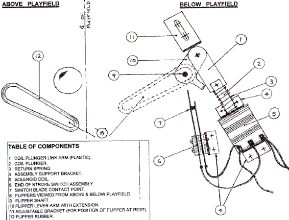
    Does anyone know if there way to hardwire normally open EOS switches? If not, can I flip them around and bend them to be NC?

    1 week later
    #48 12 years ago

    We need a update with some pictures!!!

    #49 12 years ago

    Awesome Gtech13, keep up the hard work and more updates please.....

    #50 12 years ago

    You may want to check out Pin George in Germany:

    http://www.specialpinball.com/

    His work is amazing, and he has been working on recreating Wizard Blocks, which was never produced. He may be interested in your work, and the two of you may benefit each other.

    I'm surprised you made it as far as you have, in that many have ideas of doing something like this, but quickly realise how difficult it will be. The display construction... - the fact that you are willing to build that from the ground up is amazing!

    There are 90 posts in this topic. You are on page 1 of 2.

    Reply

    Wanna join the discussion? Please sign in to reply to this topic.

    Hey there! Welcome to Pinside!

    Donate to Pinside

    Great to see you're enjoying Pinside! Did you know Pinside is able to run without any 3rd-party banners or ads, thanks to the support from our visitors? Please consider a donation to Pinside and get anext to your username to show for it! Or better yet, subscribe to Pinside+!


    This page was printed from https://pinside.com/pinball/forum/topic/building-my-own-pinball-machine-a-few-qs and we tried optimising it for printing. Some page elements may have been deliberately hidden.

    Scan the QR code on the left to jump to the URL this document was printed from.